![]() USER MANUAL
USER MANUAL
SxHAWK
Digital speed-to-fly
HAWK variometer
Version 9 
Important Notices
The LXNAV SxHAWK system is designed for VFR use only as an aid to prudent navigation. All information is presented for reference only. Terrain, airports and airspace data are provided only as an aid to situation awareness.
Information in this document is subject to change without notice. LXNAV reserves the right to change or improve their products and to make changes in the content of this material without obligation to notify any person or organization of such changes or improvements.
![]() A Yellow triangle is shown for parts of the manual which should be read carefully and are important for operating the LXNAV SxHAWK system.
A Yellow triangle is shown for parts of the manual which should be read carefully and are important for operating the LXNAV SxHAWK system.
![]() Notes with a red triangle describe procedures that are critical and may result in loss of data or any other critical situation.
Notes with a red triangle describe procedures that are critical and may result in loss of data or any other critical situation.
![]() A bulb icon is shown when a useful hint is provided to the reader.
A bulb icon is shown when a useful hint is provided to the reader.
1.1 Limited Warranty
This LXNAV SxHAWK product is warranted to be free from defects in materials or workmanship for two years from the date of purchase. Within this period, LXNAV will, at its sole discretion, repair or replace any components that fail in normal use. Such repairs or replacement will be made at no charge to the customer for parts and labour, the customer shall be responsible for any transportation cost. This warranty does not cover failures due to abuse, misuse, accident, or unauthorized alterations or repairs.
THE WARRANTIES AND REMEDIES CONTAINED HEREIN ARE EXCLUSIVE AND IN LIEU OF ALL OTHER WARRANTIES EXPRESSED OR IMPLIED OR STATUTORY, INCLUDING ANY LIABILITY ARISING UNDER ANY WARRANTY OF MERCHANTABILITY OR FITNESS FOR A PARTICULAR PURPOSE, STATUTORY OR OTHERWISE. THIS WARRANTY GIVES YOU SPECIFIC LEGAL RIGHTS, WHICH MAY VARY FROM STATE TO STATE.
IN NO EVENT SHALL LXNAV BE LIABLE FOR ANY INCIDENTAL, SPECIAL, INDIRECT OR CONSEQUENTIAL DAMAGES, WHETHER RESULTING FROM THE USE, MISUSE, OR INABILITY TO USE THIS PRODUCT OR FROM DEFECTS IN THE PRODUCT. Some states do not allow the exclusion of incidental or consequential damages, so the above limitations may not apply to you. LXNAV retains the exclusive right to repair or replace the unit or software, or to offer a full refund of the purchase price, at its sole discretion. SUCH REMEDY SHALL BE YOUR SOLE AND EXCLUSIVE REMEDY FOR ANY BREACH OF WARRANTY.
To obtain warranty service, contact your local LXNAV dealer or contact LXNAV directly.
Revision History
| Date | Revision | Revised by | Description |
| December 2024 | 1 | UK | Initial release of this manual |
| January 2024 | 2 | UK | Minor corrections |
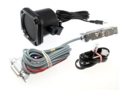
Packing Lists
- LXNAV SxHAWK main unit
- Main power cable for SxHAWK + CAN terminator
- Speaker
- Flarm cable (optional)
- PDA cable (optional)
- 2×6 mm screw
- Bluetooth antenna
- GPS antenna
- Barogram calibration chart
Second Seat (optional):
- Main SxHAWKD unit
- Y cable splitter (optional, only with remote stick)
- Main 3m CAN cable
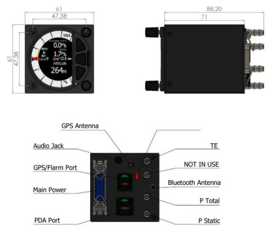
2.1 SxHAWK (57mm) Variometer Unit
2.2 SxHAWK (80mm) Variometer Unit 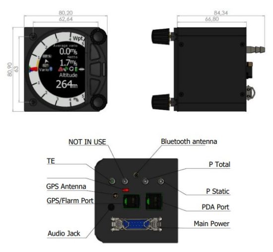
Basics
3.1 LXNAV SxHAWK at a Glance
The LXNAV SxHAWK is a standalone digital HAWK variometer. The LXNAV SxHAWK has both GPS/FLARM and PDA/PNA input/output. The unit has standard dimensions that will fit into a glider panel with an opening of 80 mm diameter (3.15”) or 57 mm diameter. It is also able to supply a PDA/PNA with power (5VDC/1A). The unit has an integrated high precision digital pressure sensor and inertial platform. The sensors are sampled more than 100 times per second. Real Time Data is displayed via a vario needles, up to 4 variable numeric fields displayed on a QVGA 320×240 pixel, 3.5-inch (SxHAWK 80mm) or 2.5-inch (SxHAWK), high brightness (1200 nits) colour display. To adjust values and settings the LXNAV SxHAWK has two rotary push button knobs and three additional push buttons.
The LXNAV SxHAWK can be expanded with one or more repeaters via the CAN bus. This allows both pilots in a two-seat glider to have independent control of all functions of each unit in the front or the rear seat. The SxHAWK unit includes a built-in IGC-approved flight recorder, a Bluetooth module and its own backup battery which provides from 3 to 4.5 hours of independent operation.
The SxHAWK is also capable of running HAWK system, which provides pilot a real-time threedimensional wind. You can learn more about HAWK in chapter 7
3.2 LXNAV SxHAWK Features
- An extremely bright 3.5’’ (SxHAWK 80MM) or 2.5” (SxHAWK) QVGA colour display readable in all sunlight conditions with the ability to adjust the backlight.
- Two rotary switches (knobs) with push button function and three push buttons are used for input.
- Pre-loaded polar database for nearly all gliders.
- GPS/FLARM and PDA/PNA input/output.
- FLARM Indication if a FLARM is connected to the GPS/FLARM port.
- Programmable “needles” for selectable data such as netto vertical speed, relative (super netto) and vertical speed (vario).
- 320×240 pixels colour screen for additional information such as average, thermal vario, time, speed etc…
- Many custom audio settings.
- 100Hz sampling rate for very fast response.
- Speed to fly indication.
- TE compensation can be selected to be either pneumatic TE probe or electronic TE.
- Audio equalizer, for custom vario sound performance.
- Audio thermal assistant.
- Built-in high level, IGC-approved flight recorder.
- Built-in Bluetooth module.
- Backup battery.
- Engine noise level sensor (ENL).
- Built-in GPS module.
3.2.1 Interfaces
- FLARM port input/output on RS232 level (RJ12 connector, none-Standard IGC) (12V/2A)
- PDA port input/output on RS232 or TTL level for PDA/PNA devices with 5V power supply (8 pin RJ 45, 5V / 1A).
- Audio port (Standard 3mm phone jack).
- 1Mbit CAN bus for extension to SxHAWKD repeater, Remote stick (CAN remote), MOP2 sensor.
3.2.2 Options
By using a CAN bus system, a second seat device can be connected. The unit installed in the rear seat of the glider is independently powered and receives all the necessary data from the main unit. The communication between both units is exclusively via the CAN bus system
(Remote stick, Second seat device).
3.2.3 Technical Data
Power input 10-28 V DC.
3.2.3.1 Power Consumption
| Device | Min. Brightness (mA) | Max. Brightness (mA) | Max charge current (mA) |
| SxHAWK | 170 at (12V) | 340 at (12V) | Additionally, up to 220mA |
| SxHAWK 80m | 190 at (12V) | 320 at (12V) | Additionally, up to 220mA |
![]() Newer models using brighter displays and consumption might be higher up to 3W.
Newer models using brighter displays and consumption might be higher up to 3W.
3.2.3.2 Size and Weight
| Device | Size | Weight (g) |
| S10 | 57 mm cut-out 61x61x70mm | 348 |
| S100 | 80 mm (3.15″) standard aircraft cut-out 81x81x64mm | 515 |
3.2.3.3 Audio output power
The unit has class D amplifier. The output power depends on speaker impedance.
- 2.6W with 4Ω speaker
- 1.65W with 8Ω speaker.
3.2.3.4 Environmental limitations
- Operating temperature: -20°C to +70°C
- Storage temperature: -30°C to +85°C
- Relative humidity: 0%-95%
System Description
4.1 Push Button – Rotary Switches
The two Rotary switches also have a push button function. The LXNAV SxHAWK detects short or long presses of the push button. A short press means just a click, a long press means pushing the button for more than one second.
4.1.1 Power Button
The system is powered up by pressing any of the push buttons or a press of either of the rotary knobs. A long press of the upper rotary knob will turn the SxHAWK off. Use this instead of the avionics master switch.
4.2 Rotary Switches
The upper rotary knob is designed for direct volume control. A short-press on the upper rotary knob will produce an option to select between options and adjust volumes for the Vario, Speech and FLARM beep.
A long-press on the upper rotary knob will shut down the system cleanly. The lower rotary knob is used to adjust settings within the current mode or within menus.
With the lower rotary push button, it is possible to toggle between the MC and the Ballast and Bugs settings. In all other menus this knob is used for setting values and editing texts.
4.3 Buttons (Three)
The three buttons between the two rotary knobs have fixed functions. The top button is ESC (CANCEL), the middle is to switch between modes and the lower button is the ENTER (OK) button.
4.4 Switching on the Unit
Pressing any of the buttons or rotary knobs will turn on the SxHAWK. The first LXNAV welcome screen will appear with the system information (Device name, Version, Serial number…)
When the boot procedure is completed the setup elevation dialogue will be displayed.
The user must set either the Elevation or the QNH with the lower rotary button. After pressing the lower rotary button, the user can switch between the Elevation and QNH dialogues. As soon as the settings are set the middle button must be pressed to proceed.
The upper push button also has the power OFF function.
4.5 User Input
The LXNAV SxHAWK user interface consists of dialogues which have various input controls.
They are designed to make the input of names, parameters, etc., as easy as possible. Input controls can be summarized as:
- Text editor
- Spin controls (Selection control)
- Checkboxes
- Slider control
To move the function from one control to another, rotate the lower rotary knob as follows:
- Clockwise rotation will select the next control.
- Counter clockwise rotation will select the previous control. The lower PUSH button enters the selected feature.
- Faster rotation of the rotary knob will increase the rate at which the value changes i.e. bigger steps in value.
4.5.1 Text Edit Control
The Text Editor is used to input an alphanumeric string; the picture below shows typical options when editing text/numbers. Use the lower rotary knob to change the value at the current cursor position. 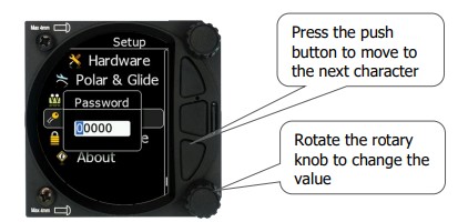
Once the required value is selected, press the lower push button to move to the next character selection. To move back to the previous character, press the upper push button. When you have finished editing, press the Enter key – the lower rotary button. A short press of the middle push button exits from the edited field (“control”).
4.5.2 “Spin” Control
“Spin” controls are designed for numeric parameters. Rotate the knob to increase/decrease the selected value. To increase a value in larger steps, spin the lower rotary knob faster. 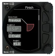 4.5.3 Selection Control
Selection boxes, also known as combo boxes, are used to select a value from a list of predefined values. Use the lower rotary knob to scroll through the list. 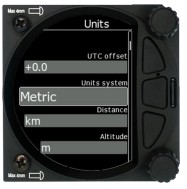
4.5.4 Checkbox and Checkbox List
A checkbox enables or disables a parameter. Press the lower rotary knob to toggle the value.
If an option is enabled a check mark will be displayed, otherwise an empty rectangle will be displayed. 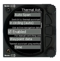
4.5.5 Slider Selector
Some values, such as volume and brightness, are displayed as a slider icon. 
With a push of the lower rotary button you can activate the slide control and then by rotating the knob you can select the preferred value and confirm it via the push button.
4.6 Switching Off
You will lose your settings if you power down the SxHAWK via the panel master-power switch.
The SxHAWK will shut down properly when switching off via the master–power switch.
To archive your settings, you should shutdown device with a long-press of the volume (top) knob.
![]() All settings are saved during the power off procedure. We strongly recommend switching off the unit by using a long-press of the (top) knob.
All settings are saved during the power off procedure. We strongly recommend switching off the unit by using a long-press of the (top) knob.
Operating Modes
The LXNAV SxHAWK has five operating modes. The middle (Menu) push button toggles through the 5 display modes in a circular way. The diagram below shows the mode structure of the LXNAV SxHAWK. With the upper and lower buttons, it is also possible to move between subpages.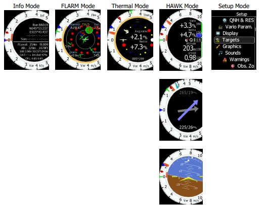
- Info Mode: Contains the GPS data, Altitude, Battery and Sunset time, OAT.
- FLARM Mode: Showing FLARM targets in range (if a FLARM device is connected to the GPS port).
- Thermal Mode: Showing a thermal assistant during circling
- HAWK Mode: Simple screen with nav boxes, Wind and AHRS sub pages
5.1 Quick Access Menus
For each mode a quick access menu is available, which varies from mode to mode. Items available in quick access menus are:
- MC/BAL
- Reset G
- Layout
- Edit target (only FLARM page)
- FLARM traffic (only FLARM page)
- Event
- Night
- Wind

To change the McCready value, press the bottom rotary knob and press on MC/BAL. A short press of the lower rotary knob moves from McCready to the Ballast box and pressing the lower rotary knob again will open the Bugs box. If no action is performed within 3 seconds, the box will close, or you can also press CLOSE anytime (lower push button).
5.1.1 Reset G
“Reset G” is a method of re-setting the “G” meter if configured as the yellow bar on the vario scale.
5.1.2 Layout
The sidebar, number and position of navboxes can be defined in this menu. The position (vertical or horizontal) is set by rotating the lower rotary knob. After confirming you can set number of navboxes and also define which navbox you would like to have. The layout setting is different for the numerical or graphical page.
5.1.2.1 Layout in the Numerical Page
In the numerical page the number of navboxes and sidebar can be set. Every navbox can be defined separately. 
5.1.2.1.1 Editing Navboxes
You can select the required data for the highlighted navbox. A short press of the lower rotary knob selects the desired setting and returns you to the navbox selection.
Selecting the EXIT (middle) button at any time saves the setting and moves to the main mode. 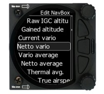 List of available navboxes:
| Type | Navbox title | Description |
| Altitude (m) | Alt | Altitude in Meters |
| Altitude (ft) | Alt | Altitude in Feet |
| Flight level | FL | Flight level |
| Hgt.above tkoff. | Hgt | Height is the vertical distance above takeoff. |
| Total Altitude | Alt T | Altitude which considers also the kinetic energy |
| Standard altitude | AltS | Altitude above 1013.24hPa |
| Gained altitude | AltG | Gained altitude in last thermal |
| Current vario | Var | Current vertical speed |
| Netto vario | Net | Vertical speed of air mass |
| Vario average | Var A | Average vario (average vario time can be set) |
| Netto average | Net A | Average vertical movement of air mass |
| Thermal avg. | Thrm | Average vario from beginning of circling (Green T) |
| HAWK Avg.Net | hNetA | HAWK netto average |
| HAWK Avg.Var | hVarA | HAWK vario average |
| HAWK sideslip | hSlip | HAWK sideslip angle |
| HAWK AOA | hAOA | HAWK angle of attack |
| True airspeed | TAS | True airspeed |
| Indicated airspeed | IAS | Indicated airspeed |
| Ground speed | GS | Speed over ground, taken from GPS |
| Speed to fly | STF | Calculated speed to fly from MC setting (McSpeed) |
| Ground Track | Trk | Track over ground taken from GPS |
| Current glide ratio | E | Glider current glide ratio in last three minutes |
| Theor.glide ratio | theE | Theretical glide ratio including wind into account |
| Gliding efficiency | glE | Ratio between current E and theoretical E |
| Local Time | Time | Local time |
| Flight time | Flt T | Airborne time |
| G-load | g | G load – current |
| G-load min.flight | gmin | Minimum g-load during flight |
| G-load max.flight | gmax | Maximum g-load during flight |
| MacCready L/D | Emc | Calculated glide ratio at selected McCready value |
| MacCready | Mc | McCready setting |
| Active freq. | COM | Active frequency |
| Standby freq. | STBY | Standby frequency |
| XPDR Transp. | XPDR | Transponder frequency |
| Outside temp. | OAT | OAT – Outside air temperature |
| Battery voltage | Battery | Battery voltage |
| Average wind | Wind | Wind direction and speed |
| Wind comp. | cWnd | Wind component (first number is component calculated from GS-TAS / second number is a component from a Wind vector) |
| Flap Current | Current flap position | |
| Flap Requested | Requested flap position |
![]() To configure navboxes in SC mode on the ground you must first turn Auto SC off, configure your navboxes and then set Auto SC back to your preferred setting.
To configure navboxes in SC mode on the ground you must first turn Auto SC off, configure your navboxes and then set Auto SC back to your preferred setting.
The unit will automatically switch between SC to VARIO navboxes, when switching from SC to VARIO mode or vice versa
5.1.2.1.2 Sidebar
The user can select between the different sidebar options that can be displayed on the page (classic Speed to Fly-push/pull bar, Flaps tape, Speed tape and combined Speed & Flap tape).
The Speed to Fly bar is dynamic. 
5.1.3 Edit Target
The user can edit the FLARM target details.
5.1.4 FLARM Traffic
This mode shows all available FLARM traffic around the glider with their FLARM ID codes; the user can also edit all FLARM object data.
5.1.5 Event
Event is used to log an event. The recording rate will be increased to 1 second for one minute.
A message “Event marked” will be displayed on the screen. ![]()
At same moment PEV message will be sent to connected flarm or nano device.
5.1.6 Night
Selecting night will cause the unit’s brightness to be decreased to its minimum. Pressing again on “night” will reset the brightness to the value defined under settings.
5.1.7 Wind
Here you can switch between automatic wind calculation by the instrument or setting the wind parameters yourself. When Wind calculation is disabled you can manually set the wind speed and direction. 
5.2 Info Mode
The Info Mode gives you a snapshot of the GPS position, date and time along with the Flight level, altitude, Battery status and FLARM status. The Flight Level equivalent is also available in meters or feet as is the Altitude navbox. 
Description:
- The logger status is displayed as Stop or Run.
- The GPS status is displayed as OK, BAD, NODATA together with the number of satellites.
- Latitude and longitude
- Local time and date
- Sunrise and sunset time.
- Flight level also in meters
- Altitude in meters and ft
- Battery status
- IGCAlt – IGC altitude (altitude read from the IGC sensor)
- FLARM status (TX – transmits data / and a number of received FLARM devices)
- OAT – outside air temperature
- GFL – G-force levels. Minimum and maximum recorded G-force level
5.2.1 Quick Access Menu
A short press of the (lower) rotary button activates the Quick Access menu.
5.3 FLARM Mode
If the SxHAWK is connected to a FLARM source via the FLARM port then the FLARM Mode will display a map of the relative positions of FLARM targets that are within range. By rotating the lower rotary knob you can change the range of the display from 0.5 km to 150 km. Switching between FLARM targets is possible via the up/down button. Data from a selected FLARM object can be seen in 4 corners: FLARM ID, Distance, Vario and Relative altitude (Above / Below). There is also an indication of how many FLARM objects are present displayed as:
TX/number.
![]() This mode can be disabled via Setup>graphics>modes>FLARM mode.
This mode can be disabled via Setup>graphics>modes>FLARM mode.
![]() Distance, relative altitude and vario indications are related to the selected target.
Distance, relative altitude and vario indications are related to the selected target.
5.3.1 Quick Access Menu
A short press of the lower rotary button activates the Quick Access menu.
5.3.1.1 Edit Target
The user can edit the following FLARM objects data:
- FLARM ID
- Competition sign
- Pilot
- Aircraft type
- Registration
- Airfield
- Communication frequency (object’s communication frequency)
These settings can be accessed by pressing the lower rotary button, selecting EDIT target and then modifying the data of interest.
5.3.1.2 FLARM Traffic
All FLARM objects in range are displayed in this mode. The following details are shown:
- FLARM target ID
- Relative distance
- Vertical speed (vario data from the object)
- Relative altitude
If you press on the selected FLARM target you can enter the edit target menu where you can insert a target’s data.
5.3.2 FLARM Warnings
Regardless of which Mode you are in, if a FLARM target triggers an urgent (third warning level) or important (second warning level) warning then the screen will change to the FLARM warning mode automatically.
Extract from the FLARM Operating Manual:
Warnings are given in order of the time remaining before a potential collision, not the geometrical distance. The first warning level for another aircraft or an obstacle is delivered at less than 19 – 25 seconds before the possible collision; the second warning level is delivered at less than 14 – 18 seconds before; the third level at less than 6 – 8 seconds before. 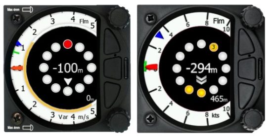
The warnings continue as long as FLARM calculates a threat of collision. The warning level may decline or be cancelled, depending upon the prediction. The warnings are selective; they are only issued if the calculation reveals a high probability of collision in the near future.
5.4 Thermal Assistant Mode

The Thermal Assistant mode displays a graphical representation of your location within the thermal. If you are thermaling to the left, there will be an aircraft symbol on the right of the ring of bubbles and the bubbles will appear to rotate clockwise (towards the symbol of the glider). If you are in a right-hand thermal there will be an aircraft symbol on the left and the ring of bubbles will appear to rotate anticlockwise (towards the symbol of the glider). Large red bubbles indicate the strongest lift within the thermal and small blue dots indicate the weakest lift or sink within the thermal. Yellow bubbles indicate lift equal to your MacCready setting, average thermal or average climb rate depending on your preferred setting. The point of strongest lift is indicated by a white large bubble.
You can use the thermal assistant to visually determine which part of the thermal has the strongest lift and adjust your turn accordingly to manoeuvre the glider in the direction of the strongest lift and away from the weakest lift or sink.
The thermaling assistant can be set to automatically change to the Thermal assistant mode or it can be manually selected. See Chapter 5.6.7.2.1 for settings.
The two navboxes within the Thermal Assistant Mode can be configured using the quick access menu.
![]() This page can be configured via: Setup->graphics->modes->thermal mode.
This page can be configured via: Setup->graphics->modes->thermal mode.
![]() Look out of the cockpit!
Look out of the cockpit!
Looking into thermal assistant might be life-threatening for you and other pilots in the thermal.
5.4.1 Quick Access Menu
A short press of the (lower) rotary button activates the Quick Access menu.
5.5 HAWK Mode
The HAWK Mode can display three different pages. Numerical scree, wind screen and AHRS screen.
5.5.1 Numerical page
The Waypoint mode has a second page which contains numerical data. Default are 4 navboxes: Average Vario, Netto, Altitude and True Airspeed. In addition, the central line shows the status of the FLARM, GPS, Cruise/Climb and battery status. This second page can be selected by pressing the lower push button once. You can return to the Waypoint navigation mode by pressing the upper push button (top button of the three). 
The Vario Needle can display: the Vario, Netto, Relative or Speed to fly value (Setup>Hardware->Indicator). The scale can be chosen in the range of +/-5 +/-10 or +/-20. The cursor style can be thin, medium or thick. It can be linear or non-linear (setup->graphics>indicator). Within the software the range can be set to m/s, kts, km/h, mph or fpm (in Setup, Units, Vertical speed).
The HAWK needle will show same parameter as Vario needle but calculated with HAWK algorithm. To learn more about HAWK setup see chapter 7.6.1 and 7.6.2.
- SideBar can be configured to display a Speed to fly bar, Speed tape or flap tape.
The Speed to fly bar symbol indicates which speed you must fly relative to the current MacCready setting, sink rate and speed. One arrow means 10 units of speed faster or slower
Speed Tape represents the Indicated Air Speed (IAS) in speed tape form depending on the speed settings (see Polar & Glider – Speeds). The speed tape will change colour from green, yellow to red depending on the settings and the IAS.
Flap Tape can display the recommended flap position. If a Flap sensor is present on the CAN bus, the flap tape will also display the actual flap position.
Speed and Flap tape is a mix of both, speed and flap tape. - The Red diamond symbol can show Netto, Average Netto, Average vertical speed or Gforce.
- The Blue arrow symbol shows the current MacCready value.
- The Green T symbol represents last thermal average value.
- The Yellow Bar can show Max and Min values of vario over defined time (average vario) or G meter (over whole flight).
- The FLARM Status symbol indicates the presence of a FLARM unit (grey), if the FLARM receives any data from other FLARM units, the symbol becomes red.
- The GPS symbol is green when the GPS status ID is OK, and red when GPS status is bad.
If GPS data is not detected, the symbol will disappear.
The numerical navboxes can be changed using the Quick Access menu with a short press of the lower rotary knob followed by selecting navbox from the menu and a further short press of the lower rotary knob. With the first navbox highlighted with a yellow border you can scroll through the four navboxes using the lower rotary knob. Select the navbox you wish to change with a short press of the lower rotary knob. This will open a list of available navboxes. 
Select the required navbox and then save this with a short press of the lower rotary knob. Repeat the process for any other navbox that needs to be changed.
5.5.2 Wind Page
On this page live wind vector and averaged wind vector are shown. Live wind is presented in blue colour when HAWK option is active otherwise it is in white colour. Second grey coloured arrow in the background is used for averaged wind. Average wind is calculated from all checked wind methods.
The third, yellow arrow is an optional and shows direction to better energy. The energy arrow can be enabled or disabled.
Wind arrows are always drawn relative to glider orientation. E.g.: If arrows are pointing downward, it indicates head wind. If arrows are pointing left or right, it means side wind. When using HAWK option, default average time for wind is set to 30 seconds. User can modify it in Vario parameters. If HAWK option is not used, averaging time is fixed to three minutes. To learn more about HAWK see chapter 7.
5.5.3 AHRS Page
The Waypoint mode has a fourth page which displays the AHRS. 
![]() The Pitch offset can be adjusted via the lower rotary knob.
The Pitch offset can be adjusted via the lower rotary knob.
![]() For competitions the artificial horizon can be disabled via the Setup>Hardware>Ahrs menu. See chapter (5.6.11.6) for more details. When the artificial horizon page is active a BFION event is written to recorded flight for verification purposes.
For competitions the artificial horizon can be disabled via the Setup>Hardware>Ahrs menu. See chapter (5.6.11.6) for more details. When the artificial horizon page is active a BFION event is written to recorded flight for verification purposes.
5.5.4 Quick Access Menu
A short press of the (lower) rotary button activates the Quick Access menu.
5.6 Setup Mode
The setup mode allows you to change the configuration and base settings for the SxHAWK vario. 
Following items are listed in the setup menu:
- QNH &RES
- Flight recorder
- Vario parameters
- Display
- Files
- Logbook
- Graphics
- Sounds
- Observation Zones
- Warnings
- Units
- Hardware
- Polar & Glider
- Password
- About
You can scroll up and down the list of settings by rotating the lower rotary knob and selecting a setting to change with a short press of the lower rotary knob.
![]() All menus have the EXIT button which will exit to the previous menu. You can also exit from the menu if you press the middle push button.
All menus have the EXIT button which will exit to the previous menu. You can also exit from the menu if you press the middle push button.
Some of the options have sub menus and these are selected in the same way.
5.6.1 QNH
This feature may be used to offset the altitude datum as the result of pressure changes during the flight. Since changing the QNH influences the indicated altitude, care should be taken when changing the value as an incorrect setting could upset the final glide calculation.
5.6.2 Flight Recorder
The SxHAWK vario system has a built-in IGC-approved flight recorder. In this menu the user can set flight recorder parameters and the pilot’s data.
5.6.2.1 Recording Interval
Set the recording interval from 1 – 20 seconds.
5.6.2.2 Auto Finish
If this functionality is enabled, the flight recorder will automatically finish the flight under the following conditions:
- GPS status OK
- Groundspeed lower than 20 km/h
- True airspeed lower than 40km/h
- Absolute vario lower than 1m/s for 300 seconds
5.6.2.3 Finish Before OFF
If this setting is enabled the flight will be finished if the user powers down the unit.
5.6.2.4 Pilot
Insert the pilot’s name which will be stored in the declaration.
5.6.2.5 Co-Pilot
If the system is used in a two-seater the name of the co-pilot may also be entered.
5.6.2.6 Competition Number
Insert the competition number of the glider which is also stored in the flight file.
5.6.2.7 Registration Number
Insert the registration number of the glider which is also stored in the flight file.
5.6.2.8 Task edit
Selecting the edit task via a short press of the lower rotary knob will enter the task editing screen. The first time you edit a task it will be blank. A short press of the lower rotary knob will open another menu with the option to:
- Edit,
- Insert,
- Delete,
- Zone,
- Delete All
- Options
Selecting Insert will allow you to enter a waypoint from the list as a start point. Rotating the lower rotary knob moves you through the waypoint list in alphabetical order, clockwise increases the value, counter-clockwise decreases the value. To select the first letter of the desired waypoint, rotate the lower rotary knob, then press the lower push button to move to the selection of the next letter. Rotate the lower rotary knob until the second letter of the required Waypoint is highlighted and then repeat the process until the required waypoint is the only selection available. Press ENTER to select the waypoint. Once the start point is selected, rotate the lower rotary knob clockwise and click to select the second turn point. Edit the second turn point as above. Repeat for all the points in the task. When you have completed editing the task, press the (middle) button to save the task and return to the Flight declaration menu.
5.6.3 Vario Parameters 
5.6.3.1 Vario Needle Filter
Vario needle filter sets a time constant of the Vario needle. The value can be adjusted between 0.1 and 5 s with step 1.0s or 0.1s. Default value is 2.0 s.
A lower number (0.1s compared to 5.0 s) means very sensitive (fast vario).
5.6.3.2 Vario Sound Filter
Sets a time constant of the Vario sound. The value can be adjusted between 0.1 and 5 s in steps of 1.0 s or 0.1 s. Default value is 2.0 s.
5.6.3.3 Netto Filter
Sets a time constant of the Vario Netto needle. The value can be adjusted between 0.1 and 5 s in steps of 1.0 s or 0.1 s. Default value is 4.0 s.
5.6.3.4 Relative Filter
Sets a time constant of the Vario Relative needle. The value can be adjusted between 0.1 and 5 s in steps of 1.0 s or 0.1 s. Default value is 4.0 s.
5.6.3.5 SC Filter
SC filter sets a time constant of the Speed-To-Fly needle. The value can be adjusted between 0.1 and 5 s in steps of 1.0 s or 0.1 s. Default value is 4.0 s.
5.6.3.6 Smart Filter
Using the Smart vario filter the vertical speed can be further filtered. The Smart vario filter defines the maximum speed of the vario needle. “1” is the highest damping, “8” the lowest.
“Off” means no additional filtering.
5.6.3.7 Needle Range
Needle range sets the full-scale range of the vario (2.5 m/s, 5 m/s or 10 m/s). Default value is 5 m/s (10 kts).
5.6.3.8 Auto SC (Speed Command)
Auto SC defines the conditions when the instrument (needle) will switch automatically between vario and speed to fly mode. It is just a needle mode.
- OFF: Switching exclusively by means of an external switch connected to the SxHAWK. With new versions of Remote sticks there is no longer a “physical” switch connection between the Remote stick and the Vario unit – it is a switch on the Remote stick which is connected through the RS485 bus.
- GPS: When the GPS detects that the glider is circling an automatic change over to vario will happen after approximately 10 seconds. Detection of straight flight will cause a change to speed command.
- IAS: When the IAS exceeds a pre-set value. The IAS at which switching occurs can be selected in 5 km/h steps from 100 up to 160 km/h (or the equivalent in knots or mph).
- G-meter – for switching between cruise and climb mode based on the G measured by the inertial system. When glider starts circling the SxHAWK will automatically switch from cruise to climb mode.
- NMEA input – if NMEA input is selected, the SC will be controlled via communication cable, which is connected to LX9xxx. LX9xxx will provide SC status via NMEA0183 communication. Please enable PLXVS sentence on Lx9xxx, to enable this function.
![]() The external switch wired to the LXNAV SxHAWK has absolute priority and will override all other switching methods. VP (Vario priority) input can also override a hard-wired SC switch.
The external switch wired to the LXNAV SxHAWK has absolute priority and will override all other switching methods. VP (Vario priority) input can also override a hard-wired SC switch.
![]() To configure navboxes in SC mode on the ground you must first turn Auto SC off, configure your navboxes and then set Auto SC back to your preferred setting.
To configure navboxes in SC mode on the ground you must first turn Auto SC off, configure your navboxes and then set Auto SC back to your preferred setting.
5.6.3.8.1 External SC switch not installed
If you do not have an external SC switch or Flap switch, you must do this manually.
The procedure is as follows:
- Go below the hardware input settings
- Assign one of the inputs as a “SC switch”
You have two SC switch states, red and green. One of them will switch the unit to cruise mode and you can change the values on each page.
When done, change the input back to the default and enable SC switch to GPS mode.
5.6.3.9 TE Compensation
The LXNAV SxHAWK offers two methods of vario Total Energy Compensation:
- Pneumatic TE Pitot tube
- Electronic TE compensation
![]() It is important to note that the method of TE compensation is defined when the instrument is installed by virtue of the pneumatic connections made to the TE and static ports. Changing the compensation type in the setup mode below WILL NOT change the method of compensation – the pneumatic plumbing must be changed first.
It is important to note that the method of TE compensation is defined when the instrument is installed by virtue of the pneumatic connections made to the TE and static ports. Changing the compensation type in the setup mode below WILL NOT change the method of compensation – the pneumatic plumbing must be changed first.
![]() If the TE pitot tube has been connected, TE compensation should be set to 0%. No further adjustment of the TE compensation is possible. Quality of the TE tube is the one and only factor.
If the TE pitot tube has been connected, TE compensation should be set to 0%. No further adjustment of the TE compensation is possible. Quality of the TE tube is the one and only factor.
![]() For electronic TE compensation, connect the TE port to static. Set the Vario Param TE compensation initially to 100% and then adjust this with flight testing as described below.
For electronic TE compensation, connect the TE port to static. Set the Vario Param TE compensation initially to 100% and then adjust this with flight testing as described below.
5.6.3.9.1 TE Fine-Tuning
The electronic TE compensation can be fine-tuned during flight using the following procedure:
It is essential that this is only performed in smooth air; it is not possible to tune the TE accurately in turbulent air.
- Set TE compensation to 100%.
- Accelerate up to approximately 160 km/h (75 kts) and keep the speed stable for a few seconds.
- Gently reduce the speed to 80 km/h (45 kts).
- Observe the vario indicator during the manoeuvre. At 160 km/h the vario will indicate about -2 m/s (-4 kts). During the speed reduction the vario should move towards zero and should never exceed zero.
- If the vario shows a climb the compensation is too low; increase the TE% and vice versa.
- Try another “zoom” to assess the change and make further adjustments if necessary.
Electronic TE compensation is only effective when the Pitot tube and static sources are colocated and the pneumatic lines to the instrument are approximately the same length. The best sensor to use is the combined pitot/static Prandtl tube. If problems are experienced with the electronic TE compensation the most likely cause is the glider’s static source.
The static source can be checked by plumbing the pneumatic tubes for electronic compensation and then setting the TE: to 0%. In still air accelerate to approximately 160 km/h (75kts) and slowly reduce the speed to 80km/h (45kts). Observe the vario indicator. If the static source is good the vario should immediately start to move to show a climb. If the needle initially shows increased sink and then moves to a climb, the static source of the glider is unsuitable and there is no way to provide successful TE compensation electronically. The use of a dedicated and accurate fin-mounted pitot/static source such as a Prandtl tube might help.
5.6.3.10 Vario Average Time
Vario average time defines the integration period for the average netto vario in seconds. The default is 20 seconds.
5.6.3.11 Integrator Reset
If this item is enabled the average vario (integrator) will be reset to 0 when switching from SC to Vario mode.
5.6.3.12 Temperature Offset
The LXNAV SxHAWK is supplied with an external outside air temperature (OAT) sensor. With the offset setting it will correct static errors of temperature measurement.
5.6.3.13 Airspeed Offset
The user has the possibility to make an airspeed offset if the measurement is not correct.
5.6.3.14 HAWK enable/disable
Using this checkbox, pilot can switch on/off HAWK system.
5.6.3.15 HAWK wind variance
Wind variance smooths the horizontal and vertical wind (netto vario) readings. The larger the value of wind variance is, the more nervous the readings. Recommended value for wind variance is 0.11. To learn more about HAWK system, read chapter 7.
5.6.3.16 HAWK Horizontal wind average
Horizontal wind average defines period, which is used for average horizontal wind calculation, which is displayed as grey arrow on wind page.
5.6.3.17 HAWK Vertical wind average
Vertical wind average defines period, which is used for average relative and average netto calculation. Both values can be shown as navbox on numeric or graphic page.
5.6.4 Display 
5.6.4.1 Automatic Brightness
If the Automatic Brightness is checked the brightness will be automatically adjusted between the minimum and maximum parameters set. If the Automatic Brightness is unchecked the brightness is controlled by the brightness setting.
5.6.4.2 Minimum Brightness
Use this slider to adjust the minimum brightness for the Automatic Brightness option.
5.6.4.3 Maximum Brightness
Use this slider to adjust the maximum brightness for the Automatic Brightness option.
5.6.4.4 Get Brighter In
The user can specify in which time period the brightness can reach the required brightness.
5.6.4.5 Get Darker In
The user can specify in which time period the brightness can reach the required brightness.
5.6.4.6 Brightness
With the Automatic Brightness unchecked you can set the brightness manually with this slider.
5.6.4.7 Night Mode Darkness
Set the percentage of the brightness to be used after a press on the NIGHT mode button.
5.6.5 Files
The Files menu allows you to upload or select Waypoint and FlarmNet files.  5.6.5.1 Waypoints and Tasks
Selecting the Waypoints and Tasks menu opens a list of .cup files available in the internal memory. Pressing add new lists the files present on the SD card. Selected files are automatically loaded into internal memory. 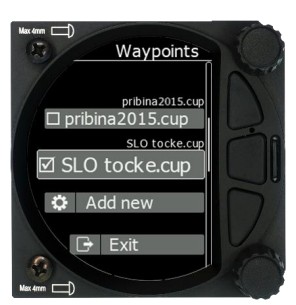
Selected files can be also removed from the internal memory after using remove function.
The file size of a waypoint file is limited to 1MB. The supported format is CUP as generated with the SeeYou program. Some versions of CUP may not be compatible if they are not created according to the CUP standard, which is a proprietary format from the Naviter company.
The number of CUP files that can be viewed or selected is 20.
5.6.5.2 Logbook
The logbook page lists all the flights sorted by date.  If GPS data is present the logbook will show the date and time of departure. Manual navigation (without GPS) will show the duration and will be marked with “—” marks.
![]() The user can download a flight by a short press on the lower rotary button.
The user can download a flight by a short press on the lower rotary button.
5.6.5.3 FlarmNet file
Selecting the FlarmNet option opens a list of .fln files available on the SD card or in the internal memory. Selecting a file loads it. 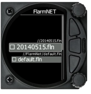 5.6.6 Logbook
The logbook page lists all the flights sorted by date.  If GPS data is present the logbook will show the date and time of departure. Manual navigation (without GPS) will show the duration and will be marked with “—” marks.
![]() The user can download a flight by a short press on the lower rotary button.
The user can download a flight by a short press on the lower rotary button.
5.6.7 Graphics
The Graphics option has sub menus for Indicator setup, FLARM, Thermal assistant and Modes.
5.6.7.1 Indicator Setup
Vario indicator graphics and preferences can be adjusted in this menu. 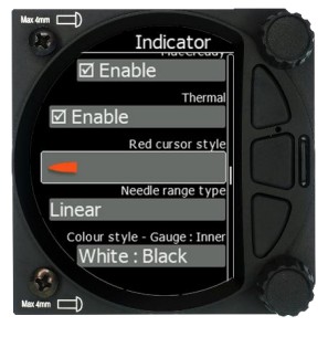
5.6.7.1.1 Needles
When HAWK option is installed, user can define, if he wants to see only HAWK (blue) needle, TEK vario (red) needle or both needles.
5.6.7.1.2 Vario Needle
Vario needle means, when your vario is in vario mode. A needle can be set to Vario, Netto, Relative or G-meter. When using HAWK option it is recommended to set Vario needle to Relative.
5.6.7.1.3 SC needle
SC needle means, when your vario is in SC mode. A needle can be set to Vario, Netto Relative or G-meter. When using HAWK option it is recommended to set SC needle to Netto.
5.6.7.1.4 Yellow Bar
Yellow bar can be set to G-meter, Min/Max vario or no bar.
5.6.7.1.5 Red Diamond
Red diamond symbol can be set to No diamond, Average, Netto, Average Netto, G-meter or SC.
5.6.7.1.6 MacCready
The blue triangle can be enabled or disabled.
5.6.7.1.7 Thermal
The green T can be enabled or disabled.
5.6.7.1.8 Red Cursor Style
It is possible to pick between thin / middle or thick cursor style.
5.6.7.1.9 Needle Range Type
Non-linear needle means that positive climb numbers are not in the linear scale, but they are wider at weak climb and narrower at very strong climb rate. If you wish to always have the same space between numbers, use the linear scale.
5.6.7.1.10 Colour style – Gauge: Inner
With this dialogue you can change the background colour for the vario gauge (Outer ring) and the background of the information circle within the gauge. You have the following choices:
| Gauge | Inner |
| White | Black (default) |
| White | White |
| Black | White |
| Black | Black |
5.6.7.1.11 User msg. Transp.
With this dialogue you can change the transparency of the user messages when they are displayed overlaid on each screen from 0 to 100%. Default is 50%.
5.6.7.1.12 Navbox Transparency
With this dialogue you can change the transparency of the navboxes which are overlaid on each screen from 0 to 100%. Default is 44%.
5.6.7.2 Thermal assistant
5.6.7.2.1 Switch to Thermal Assistant Mode
When in circling is selected the SxHAWK will change to the Thermal Assistant mode when the glider starts turning in a climb. It can change to the Thermal mode also if SC mode is switched to Vario mode, if setting SC-VAR. switch is selected. If the box is disabled the thermal assistant mode can be accessed manually.
5.6.7.2.2 Thermal Assistant Ping Method
If the Thermal assistant ping method is enabled the user will hear a PING during circling.
When the PING is heard the pilot must expand the circle to centre the thermal. In the settings there are two methods available to trigger the PING: time before thermal maximum and angle before thermal maximum. The ping volume is related to speech volume setting.
5.6.7.2.3 Time before Ping
Using this method, the user will hear a PING (different audible signal) the selected number of seconds before maximum of thermal.
5.6.7.2.4 Angle before Ping
Using this method, the user will hear a PING (different audible signal) the selected number of degrees before maximum of thermal.
5.6.7.3 FLARM  In this menu you can choose to show FLARM traffic on the map, select target on map only, change glider colours and adjust the FLARM object timeout and graphical settings.
5.6.7.3.1 Traffic on Map
Check the dialogue box to display FLARM objects on the screen.
5.6.7.3.2 Select Target on Map Only
There will be only the selected target on the map.
5.6.7.3.3 Colours
Colours can be set for the following:
- Glider Above Colour
- Glider Below Colour
- Glider Near Colour
- Selected target Colour
5.6.7.3.4 Label Text
On the map it is possible to show additional, related text next to the FLARM object.
This option can be set to None, Competition sign, Climb rate and Relative vertical.
5.6.7.3.5 Active Timeout
Adjusts the time a glider symbol remains on the map after it has last been seen by the FLARM.
5.6.7.3.6 Inactive Timeout
Inactive timeout setting sets the time for inactive gliders on the FLARM target list. Inactive gliders are gliders where the FLARM signal has been lost for a period longer than the Active timeout. The targets become inactive and remain only in the FLARM target list for this time.
5.6.7.3.7 Draw Line to Selected Target
Check this option to enable or disable a line drawn to a selected FLARM target.
5.6.7.3.8 Draw History
Select if a trail is to be drawn behind FLARM targets to show where the targets have been.
5.6.7.3.9 Plane Icon size
Use this item to adjust the pixel size of FLARM targets.
5.6.7.4 Modes
Thermal and FLARM modes can be disabled via this menu.
5.6.8 Sounds
The sounds option has a sub menu for Equalizer, Vario and FLARM.  5.6.8.1 Equalizer Option
With the lower rotary knob, you can adjust the volume for each frequency. The settings are stored when you exit the screen (via the middle button). 
5.6.8.2 Vario Sounds  In this menu the user can change all the parameters for vario sounds.
![]() The volume for Vario, FLARM and Speech can also be adjusted directly via the upper rotary knob.
The volume for Vario, FLARM and Speech can also be adjusted directly via the upper rotary knob.
5.6.8.2.1 Vario Volume
The user can set the default vario volume.
5.6.8.2.2 Sound shape
In this menu, you can choose between following shapes: Sinus, Triangular and Harmonic.
5.6.8.2.3 Vario audio mode:
- Linear positive: the sound is interrupted with silence every few milliseconds when the needle is positive; on negative side sound is linear (not interrupted).
- Linear negative: inverse function to Linear positive.
- Linear: the sound is linear and non-interrupted in full scale range.
- Digital positive: similar to Linear positive, except the way of beeping is sl
- Digital negative: inverse function to Digital positive.
- Linear positive only: the sound is present only at positive values, for negative values there is silence.
- Digital positive only: similar function to Linear positive only, except the sound is imilar to the digital tone.
- Digital: similar function to Linear, except the sound is similar to the digital tone. The frequency is not changing linearly, but by steps. Sounds like playing a flute.
5.6.8.2.4 SC Audio Mode
SC audio mode has five modes:
- SC positive: the sound is interrupted with silence every few milliseconds when the needle is positive; on negative side sound is linear (not interrupted).
- SC negative: inverse function to SC positive.
- SC: the sound is linear and non-interrupted in full scale range.
- SC Mixed: for positive relative values the sound represents relative; for negative relative values the sound represents SC (for that setting it is recommended to set SC needle to relative).
- Relativ: the variometer will produce the same sound as defined in Vario audio, except it will follow relative speed values.
5.6.8.2.5 Vario Audio source
Vario audio source is shown when HAWK option is activated. You can choose between HAWK or TE vario audio source for variometer sound.
5.6.8.2.6 SC Audio source
SC audio source is shown when HAWK option is activated. You can choose between HAWK or TE vario SC audio source for speed to fly sound.
5.6.8.2.7 Dead band
Dead band setting defines the width of the audio dead band in speed to fly mode. Default value is ±1 m/s.
5.6.8.2.8 Audio Frequencies
- Freq at 0% defines the tone frequency at 0 m/s.
- Freq at +100% defines the tone frequency at full + deflection.
- Freq at -100% defines the tone frequency at full – deflection.
5.6.8.2.9 Equalization Pre-Sets
We have three options: default LXNAV speaker, flat setting or user defined.
![]() The volume for Vario, FLARM and Speech can also be adjusted directly via the upper rotary knob.
The volume for Vario, FLARM and Speech can also be adjusted directly via the upper rotary knob.
5.6.8.2.10 Voice test
Press this button in order to test quality of voice messages.
5.6.8.3 FLARM Sounds 
5.6.8.3.1 FLARM Volume
Adjust the default FLARM volume with the slider.
5.6.8.3.2 FLARM Low Alarm
For distant FLARM targets the SxHAWK gives a short or long message, just a beep or be turned off (19-25 seconds before possible collision).
5.6.8.3.3 FLARM Important Alarm
For close FLARM targets the SXHAWK can give a short or long message, just a beep or be turned off (14-18 seconds before possible collision).
5.6.8.3.4 FLARM Urgent Alarm:
For very close FLARM targets the SxHAWK gives a short or long message, just a beep or be turned off (6-8 seconds before possible collision).
![]() The volume for Vario, FLARM and Speech can also be adjusted directly via the upper rotary knob.
The volume for Vario, FLARM and Speech can also be adjusted directly via the upper rotary knob.
For the alarm sound the user has the possibility to select between beep, short message and long message sounds.
Short message is of the form: “Traffic two o’clock”
Long message sounds like: “Traffic two o’clock, two kilometres, two hundred meters above”.
5.6.9 Warnings  There are FLARM, Altitude and Airspace warnings.
5.6.9.1 FLARM
5.6.9.1.1 Enable FLARM Warnings
Warnings can be enabled or disabled in this section.
The warning dismiss time can be set from 0 to 120 seconds.
5.6.9.1.2 Display PCAS Alarms
Check this item to see non-directional traffic on the FLARM screen. Non-directional traffic will be drawn with a dotted circle at the received distance from the aircraft position. The PCAS timeout is setup separately in the next time spin control.
5.6.9.1.3 Display Urgent Alarms
Third level approximately 8 seconds before predicted collision.
5.6.9.1.4 Display Important Alarms
Second level approximately 13 seconds before predicted collision.
5.6.9.1.5 Display Low Alarms
First level approximately 18 seconds before predicted collision.
5.6.9.1.6 Dismiss While Circling
This dismisses FLARM alarms for FLARM targets in the same thermal. FLARM warnings for urgent alerts override this.
5.6.9.1.7 Dismiss Time
If a FLARM warning is dismissed, there will be no FLARM warnings for the number of seconds set in that menu. Once a certain FLARM alarm is set off you can dismiss it for that set amount of second by pressing the lower knob.
5.6.9.2 Visual Messages/Warnings 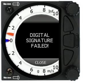 The SxHAWK will provide the following visual messages/warnings:
- Digital signature failed (it will appear immediately after initial setup)
- Freezing temperature (it is related to the OAT measurement)
- Outside zone
- Airbrakes not locked
- Check landing gear
- Low external battery
- Running on internal battery (if flight recorder is running)

- Shutting down (if flight recorder is not running and there is no external power)
- Freezing temperature (if the outside temperature is 1 degrees)
5.6.9.3 Voice Warnings
The SxHAWK will trigger the following voice warnings:
Gear Warnings
CHECK GEAR: this warning is triggered 5 minutes after take-off if the landing gear is not wired to any of the inputs of the SxHAWK.
CHECK LANDING GEAR: during the flight, gear up*, airbrakes opened*.
Airbrakes Warnings
CHECK AIRBRAKES: if you are on the ground, speed 0, gear down*, airbrakes opened*. This warning is repeated every 30 seconds.
WARNING AIRBRAKES, WARNING AIRBRAKES…: during the acceleration, gear down*, airbrakes opened*.
CHECK AIRBRAKES: speed, airbrakes opened*.
Low battery (if the battery is low – see battery chemistry setting).
Stall speed (warning is related to the stall speed set in the menu).
FLARM voice message long: Traffic at: position, distance, vertical distance.
FLARM voice message short: Traffic at: position.
*airbrakes and/or landing gear should be wired to digital inputs!
5.6.10 Units
Use this menu to specify units, UTC time offset and type of ballast input.
- UTC Offset: in half or whole hours plus or minus Zulu.
- System of units: Metric, English, US.
- Distance: Units available; statute miles, nautical miles, kilometres.
- Altitude: Units available feet, meters.
- Temperature: Units available; degrees centigrade or degrees Fahrenheit.
- Pressure: Units available; inches of mercury (inHg), mm of mercury (mmHg), mbar.
- Speed: Units available; fpm, m/s, mph, kts, km/h.
- XC Speed: Units available; fpm, m/s, mph, kts, km/h.
- Vertical Speed: Units available; fpm, m/s, mph, kts, km/h.
- Wind: Units available; fpm, m/s, mph, kts, km/h.
- Weight: lbs or kg
- Load: lb/ft2 or kg/m2
- Longitude/Latitude: DD.ddddd, DDMM.mmmmm’, DDMM’SS.ss”, DD.dddd, DDMM.mmm’, DDMM’SS”
- Ballast: weight (insert ballast in kg), load (ballast kg/m2), overload (factor of overload).
5.6.11 Hardware
The Hardware setup has a sub menu for Digital inputs, Indicator, Communications, Battery, Remote Stick, Flaps, Bridge. 
5.6.11.1 Digital Inputs 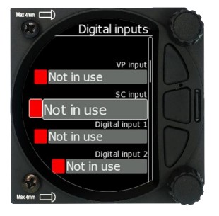
This input wires are set open (not grounded) as a factory default on delivery. You need to wire a switch between the input and ground.
5.6.11.1.1 VP Input (Vario Priority)
When this input is activated by grounding the appropriate wire, the unit will change over to Vario immediately. This switch has priority over all SC switching methods. This means it will override all other signals for SC and switch unit to vario mode. This input is not wired in standard wiring – it must be wired by the customer.
5.6.11.1.2 SC Switch
The LXNAV SxHAWK has an input for an external speed command switch. Using the external switch, it is possible to manually switch between SC and Vario. Setting the SC switch to ON mean that closing the switch will cause the instrument to enter SC mode. Setting the SC switch to OFF means that closing the switch will select Vario mode. There is a third option by setting SC INPUT to TASTER and connecting a push button to the input; each key press will toggle between SC and Vario (mandatory setting for LX Remote, which provides a push button for SC).
5.6.11.1.3 Digital Inputs 1,2,3,4
The LXNAV SxHAWK has 4 external digital inputs which can be set to indicate the state of the landing gear, airbrakes, canopy switch, tail dolly switch and event input. The wiring is described in Chapter 9.6.1.5. All inputs are open collector with internal pullup resistor. If the input left open it will indicate red (flase) state, if you ground it it will indicate green state (true).
5.6.11.1.4 Example of Warnings Triggered by the Input:
- Gear Warnings
CHECK GEAR: this warning is triggered 5 minutes after take-off if the landing gear is not wired to any of the inputs on the SxHAWK.
CHECK LANDING GEAR: during the flight, gear up, airbrakes opened. - Airbrakes Warnings
CHECK AIRBRAKES: if you are on the ground, speed 0, gear down, airbrakes opened. This warning is repeated every 30 seconds.
WARNING AIRBRAKES, WARNING AIRBRAKES…: during the acceleration, gear down*, airbrakes opened.
CHECK AIRBRAKES: speed, airbrakes opened.
![]() Input pins are available on the rear DB15 connector, but they are not wired.
Input pins are available on the rear DB15 connector, but they are not wired.
![]() Input is active when it is shortened to ground.
Input is active when it is shortened to ground.
5.6.11.2 Communication Setup
This is used to configure the two ports on the back of the SxHAWK for connecting to a GPS/FLARM source and to a PDA. Each port can be configured separately. 
5.6.11.2.1 Direct link: PDA-FLARM link
If your PDA device does not support an automatic switch to DIRECT LINK between the GPS and PDA ports, there is a manual DIRECT LINK menu. The user can select between PDAFLARM or BT-FLARM.
When automatic baud rate is enabled the LXNAV SxHAWK will automatically search on all speeds to receive valid data on the FLARM port. When the SxHAWK receives a valid NMEA sentence it will lock on that baud rate and stop searching.
![]() PDA-GPS link is normally automatic, but some PDA software requires manual settings.
PDA-GPS link is normally automatic, but some PDA software requires manual settings.
![]() Connecting the SxHAWK to the FLARM extension port can lead to insufficient data being sent. Please connect the SxHAWK to the main FLARM port.
Connecting the SxHAWK to the FLARM extension port can lead to insufficient data being sent. Please connect the SxHAWK to the main FLARM port.
5.6.11.2.2 BT-FLARM Link
Allows a PNA device connected via Bluetooth to directly communication with a device which is connected to the FLARM port (FLARM/Nano).
5.6.11.2.3 PDA Baud Rate
Set the baud rate of the PDA port.
The baud rate on the PDA port must be set to same as it is on the PDA device otherwise SxHAWK and PDA will not communicate with each other.
The baud rate on PDA must not be lower than the setting on GPS port.
5.6.11.2.4 GPS (SxHAWK-FLARM port) Baud Rate
Set the baud rate of the GPS/FLARM port.
![]() To obtain best performance from the LXNAV SxHAWK it is recommended that both baud rates are set as high as possible.
To obtain best performance from the LXNAV SxHAWK it is recommended that both baud rates are set as high as possible.
5.6.11.2.5 Bluetooth
Toggle this setting to switch ON/OFF the internal Bluetooth module. If the BT module is turned off the power consumption will be lower and the operating time of the internal battery will increase.
![]() For the Bluetooth operation, the baud rate on GPS must not be lower than 9600bps.
For the Bluetooth operation, the baud rate on GPS must not be lower than 9600bps.
5.6.11.2.6 Send Declaration to FLARM Port
This will automatically send a declaration to an external Flarm module.
5.6.11.2.7 NMEA output
NMEA output on PDA port and on BT can be enabled or disabled. If you are not using a PDA port this setting should be disabled to obtain better performance.
![]() Before using Bluetooth, a Bluetooth antenna must be connected to the unit.
Before using Bluetooth, a Bluetooth antenna must be connected to the unit.
![]() The Bluetooth password is 1234 or 0000.
The Bluetooth password is 1234 or 0000.
This Bluetooth is compatible with iOS and Android.
5.6.11.2.8 Beeps Controlled by PDA
If a PDA is connected to the SxHAWK, the PDA can send a beep command to the SxHAWK. If this feature is enabled the SxHAWK will beep on request from the PDA.
5.6.11.3 Battery Setup
SxHAWK units have 2 options listed:
- External battery
- Internal battery

5.6.11.3.1 External Battery Chemistry
The user must select the battery from the battery list to obtain the proper voltage measurement.
Batteries used in gliders today are not only the old-style lead acid battery but also Lithium Ion (LiIon) and Lithium Iron Phosphate (LiFePo) are available.
Each battery type has a different power delivery curve and it is now possible to configure the Low and High Battery warnings.  Select battery from list gives you a drop-down list with the suggested battery settings for Full Voltage, Low Battery Voltage and Empty Voltage as pre-sets. Selecting one of these will set the values in the following boxes.
  Alternatively, you can manually change the Full Voltage, Low Battery Voltage and Empty Voltage if your battery type is not listed. Those settings will influence the battery level icon and low battery warning.
5.6.11.3.2 Internal Battery
SxHAWK units have also a built-in internal battery where you can check the health and settings of this battery. 
5.6.11.3.3 Health of the Battery
This shows the health of the internal battery and its charge level. Charge level while connected to external power will indicate 100% when charging, even if battery is not full. If the battery is full it will display “FULL”. 
5.6.11.3.4 Settings of the Internal Battery 
The following values can be set:
- Preserve battery = charger will not be activated until the battery drains below 75%.
- Charge to full = if it is not checked, the battery will be charged up to approximately 90% (when charging current drops below 0.45A).
- Charger mode = can be set to ON / OFF or automatic.
Automatic mode will stop charging when the charging current drops below 10mA. Then the charge status will indicate FULL. If preserve battery is enabled, charging will take place only when the battery is below 75% and will charge to full or 90%, depends on setting.
![]() The internal battery will not supply power to any peripheral devices such as remote stick, FLARM, PDA…
The internal battery will not supply power to any peripheral devices such as remote stick, FLARM, PDA…
![]() SxHAWK will charge internal battery only when external power is present and the unit is powered on.
SxHAWK will charge internal battery only when external power is present and the unit is powered on.
5.6.11.3.5 Battery Calibration
Sometimes internal battery needs to be self-calibrated. New calibration of the battery can be done with full discharge cycle.
To start the process, charge the battery to FULL. When you see FULL, remove external power, and leave it running until internal battery is empty.
If battery is not calibrated the indication of the (state of charge) SOC % might be wrong.
Value however is always correct at the FULL charge state in every case.
5.6.11.4 Remote Stick
The remote stick is also connected to the CAN bus which is the main wiring of the SxHAWK.
The device must be registered in case of a two-seat device as it is possible to have two remote sticks; one registered to the main device and the other one to the second seat device.
Registering the remote stick can be carried out in the following way:
Press any button on the remote stick – the SxHAWKwill detect the presence of the remote stick on the CAN BUS.
Go to Setup->Hardware->Remote stick.
To confirm the remote stick, you must press the OK button on the remote stick.
The process is similar for the second remote for the SxHAWKD repeater unit. Be sure that at the time of registering repeater unit, front unit is not in Register mode, otherwise both units will listen to the same remote stick.
![]() Whilst the remote stick uses a different type of communication than the SxHAWK, the user must specify for what purpose remote stick will be used when ordering one. In case of SxHAWK instruments, an adapter named Remote CAN will be included. On one side it is connected to the CAN bus via a DB9 connector and on the other side to appropriate wires of the remote stick. Follow the colour marks on the spring contacts.
Whilst the remote stick uses a different type of communication than the SxHAWK, the user must specify for what purpose remote stick will be used when ordering one. In case of SxHAWK instruments, an adapter named Remote CAN will be included. On one side it is connected to the CAN bus via a DB9 connector and on the other side to appropriate wires of the remote stick. Follow the colour marks on the spring contacts.
![]() The CAN bus is always under power, consequently the remote stick is also under power. After the flight disconnect the batteries or turn off the master switch to prevent discharging the batteries.
The CAN bus is always under power, consequently the remote stick is also under power. After the flight disconnect the batteries or turn off the master switch to prevent discharging the batteries.
![]() The remote stick is only recognized if the system is under external 12V power. It will not work if the SxHAWK is running on the internal battery only.
The remote stick is only recognized if the system is under external 12V power. It will not work if the SxHAWK is running on the internal battery only.
5.6.11.5 Flaps
When a flap sensor is installed, use this menu to set the flaps position. Toggle SC/Vario at option allows you to select when (depending on flap position) the instrument will switch between SC and vario mode. Use the page selector to select the desired flap position. Press SET to set the position. Repeat this procedure for all flap positions.  When all flap positions are set, a green dot will be displayed with current flap position. If flap labels are not set yet, press EDIT to name the labels. Flap labels must be entered with increasing speed range. It is recommended that flaps labels are set together with the speed range in the Polar and Glider setup. It is also possible to toggle between cruise and climb mode using the flap sensor.
  5.6.11.6 AHRS
Use this menu to calibrate AHRS for installation errors.
Place your glider in levelled position and select Level, it will set system pitch offset and current pitch will be set to 0°.
You can also modify User pitch offset.
Reset off. Button will reset system pitch offset and user pitch offset to zero (Factory default).
Align gyros will adjust drift of gyroscopes, which solve the problem of small pitch and roll offset during flight.
Reset gyros will set back to factory defaults all user gyro alignments.
![]() During flight user pitch offset can be adjusted via the lower rotary knob.
During flight user pitch offset can be adjusted via the lower rotary knob.
In this menu AHRS can also be locked by Password. 
![]() The AHRS locked option may be used by contest organizers. They can lock or unlock an AHRS with their own password.
The AHRS locked option may be used by contest organizers. They can lock or unlock an AHRS with their own password.
If AHRS is Locked by Password and the password has been forgotten, please use the password 23519.
5.6.11.7 CAN Bridge
The CAN Bridge is an external device which is sold separately and is used to output NMEA data or to connect a radio or transponder to the system.
![]() Refer to the installation manual for details on the wiring of the CAN Bridge.
Refer to the installation manual for details on the wiring of the CAN Bridge.
Once a CAN bridge is plugged in to the CAN BUS, Bridge SxHAWKxxx will appear in the Hardware menu.  First, you must define the functionality. The dialogue will change based on what you select and will display relevant items.
5.6.11.7.1 NMEA Output  NMEA output is used to transmit NMEA sentences. You can select desired NMEA sentences and define the baud rate at which they will be transmitted.
5.6.11.7.2 Radio Bridge
The Radio Bridge is used to operate a radio through the main display unit. First the type of connected radio must be selected. For the list of supported devices please refer to CAN Bridge installation manual found on www.lxnav.com. 
![]() Due to Becker AR6201 not supporting RS-232 connections it is not yet supported.
Due to Becker AR6201 not supporting RS-232 connections it is not yet supported.
Selecting Config radio will open the radio setup menu. In this menu you can select Show target warnings. This will trigger warnings generated from the device (example: radio is too hot). Here you can also setup active and standby frequency, volume, squelch volume and VOX volume.
If your airport has a frequency, it will be automatically selected as standby frequency on the radio once the airport is selected. Auto select target frequency must be selected for this to work.
5.6.11.7.3 XPDR Bridge
The XPDR Bridge can operate the transponder via the main unit. You can set the ICAO Identity in the XPDR Setup menu which is opened by clicking Config XPDR. It can also show target warnings from the transponder. For the list of supported devices please refer to CAN Bridge installation manual found on www.lxnav.com. 
5.6.11.8 FLARM
If a FLARM or PowerFLARM is connected to the system its information, configuration and aircraft configuration can be seen or configured in this menu. 
5.6.11.8.1 Info
Here you can see all information about the external FLARM/PowerFLARM device. Available information is:
- Hardware
- Firmware
- Flarm ID
- Serial Number
- Obstacle database
- Obstacle date
5.6.11.8.2 Config
The FLARM configuration such as FLARM/PCAS and ADSB horizontal and vertical range can be set here. Mode C/Do not track mode and Stealth mode can be enabled or disabled. Stealth mode meaning – if enabled, other FLARM units will not receive altitude
and vario information concerning your glider (only a dot will appear on their instruments). For collision warnings this mode has no influence. Do not track enabled will not allow an object to be seen on the OGN.
5.6.11.8.3 Aircraft Config
The Aircraft type such as glider / Tow plane / Helicopter etc… can be set here. The ICAO address is the code which has to be configured in the config file if a transponder is present.
If that code is not set, a transponder in the cockpit will be seen as a FLARM object all the time.
5.6.11.8.4 Flight Recorder
The FLARM’s flight recorder settings can be modified in this menu.
5.6.11.8.5 Flarm error codes
Error codes are displayed on SxHAWK screen, flarm displays or you can read it on flarm generated files on flarm’s SD card.
11 = Firmware expired (requires valid GPS information, i.e. will not be available in the first minute or so after power-on)
12 = Firmware update error
21 = Power (e.g. voltage < 8V)
22 = UI error
23 = Audio error
24 = ADC error
25 = SD card error
26 = USB error
27 = LED error
28 = EEPROM error
29 = General hardware error
2A = Transponder receiver Mode-C/S/ADS-B unserviceable
2B = EEPROM error
2C = GPIO error
31 = GPS communication
32 = Configuration of GPS module
33 = GPS antenna
41 = RF communication
42 = Another FLARM device with the same Radio ID is being received. Alarms are suppressed for the applicable device.
43 = Wrong ICAO 24-bit address or radio ID
51 = Communication
61 = Flash memory
71 = Pressure sensor
81 = Obstacle database (e.g. incorrect file type)
82 = Obstacle database expired.
91 = Flight recorder
93 = Engine-noise recording not possible
A1 = Configuration error, e.g. while reading flarmcfg.txt from SD/USB.
B1 = Invalid obstacle database license (e.g. wrong serial number)
B2 = Invalid IGC feature license
B3 = Invalid AUD feature license
B4 = Invalid ENL feature license
B5 = Invalid RFB feature license
B6 = Invalid TIS feature license
100 = Generic error
101 = Flash File System error
110 = Failure updating firmware of external display
120 = Device is operated outside designated region. The device does not work.
F1 = Other
5.6.12 Polar and Glider
5.6.12.1 Polar
The Polar and Glider section allows you to load and edit a set of parameters for your glider’s polar. You can select from a pre-defined list of most common gliders or create your own polar.  Select Glider from List: presents you with an alphabetical list of all the common gliders and associated polar data. All glider data will be copied from the chosen polar. Verify that the best glide ratio and minimum sink rate are displayed. To see whether the polar data matches your glider’s performance, review the MacCready Setting Menu where you can verify the values.
  You can modify the polar by changing coefficients a, b and c. A polar is defined as a quadratic equation with the parameters a, b, and c.
Use the SeeYou program (Tools->Polar) to calculate coefficients a, b and c for a given glider’s polar. The program requires three sink points entered at selected speeds (e.g.: 100 km/h, 130 km/h, and 150 km/h). The program will calculate the values of a, b and c, which should be noted and entered into the LXNAV SxHAWK.
- Class: Options for Touring, Ultralight, World, Twin-seater, Club, 18-meter, 15-meter, Open, Standard and Unknown are available.
- A, b, c: Options can be adjusted or entered for a non-listed glider.
- Reference load (wing loading) value represents the value at which the polar was measured.
- Reference weight corresponds to the weight value at which the polar was measured.
- Maximum take-off weight is the maximum take-off weight allowed for the glider. It is not used in the calculation; it is just a reminder to the pilot of the maximum take-off weight. Empty weight is weight of the glider without the pilot and ballast.
- Pilot weight is the weight of the pilot with parachute and baggage.
- Co Pilot Weight is the weight of the co-pilot with parachute and baggage.

![]() In case of a two-seater configuration both users have possibilities to change parameters. The last change performed is synchronized into both instruments.
In case of a two-seater configuration both users have possibilities to change parameters. The last change performed is synchronized into both instruments.
5.6.12.2 Speeds
The user can set the following speeds:
- Stall speed (VS0)
- Stall speed (VS1)
- Approach speed (Vapp)
- Best climb (Vec)
- Max flaps (Vfe)
- Manoeuvre speed (Va)
- Max speed (Vne)
These speeds will be used as warnings such as stall speed
5.6.12.3 Flaps
For setting up flaps please refer to Chapter 5.6.11.5 for more details.
5.6.13 Password
There are several system passwords which run specific procedures as listed below:  5.6.13.1 List of Password Functions
| DELETE WHOLE LOGBOOK | 99999 |
| RESET TO FACTORY DEFAULT | 666 |
| OPTION ACTIVATION / DEACTIVATION | 30000 |
| AHRS REACTIVATE | 23519 |
| AUTO ZERO | 1043 |
| REPORT TO SD CARD | 111 |
| UPDATE FIRMWARE | 89891 |
| DELETE AHRS PASSWORD | 23519 |
| START CAN LOGGER | 43001 |
| FORMAT INTERNAL FILESYSTEM (All data will be lost) | 32233 |
5.6.14 About
In the about page information about the display platform and the sensor box can be viewed.
The user can view the following details:
- IGC serial number
- Indicator version A and B,
- Sensor box version A and B.

Variometer and Altimeter
All signals from the pneumatic sensors (altitude, speed) are derived from high quality pressure sensors, which mean that no flask is necessary. The vario signal is derived from the altitude signal. All signals are temperature and altitude compensated. The colour display shows the vario information as well as many other parameters.
The display is user configurable. The Variometer can be configured to show:
- Range 5, 10 and 2.5 m/s or 10, 20 and 5 kts.
- Time constants 0.1 s to 5 s, in addition there are 4 settings for electronic processing for the vario signal.
- Netto shows the air mass lift and sink.
- Relative shows the lift or sink that would be achieved if the glider was circling at thermaling speed.
There are two ways by which the vario indications can be corrected for total energy. Electronic TE compensation is based on speed changes with time and pneumatic compensation with a TE probe. The quality of the TE compensation depends entirely on the location, size and dimension of the TE tube. The installation must be leak-proof.
![]() If an electronic TE compensation is selected the TE (Pst) port should be connected to a good static pressure source. If pneumatic compensation is selected the TE (Pst) port should be connected to the TE probe.
If an electronic TE compensation is selected the TE (Pst) port should be connected to a good static pressure source. If pneumatic compensation is selected the TE (Pst) port should be connected to the TE probe.
6.1 Altimeter
The altimeter of the LXNAV SxHAWK is temperature compensated from -20ºC up to + 60ºC.
The altimeter is calibrated up to 20000 m.
6.2 Speed Command
Speed command flying based on the MacCready theory is a very useful tool to optimize crosscountry speed. When the instrument changes to speed command mode the audio will change and become a director informing the pilot whether he is flying too fast or too slow. To reduce confusion between vario and speed command audio some special features are incorporated:
- Continuous audio signal and other kinds of signals can be chosen. For details see setup.
- No audio at correct speed (dead band).
HAWK
7.1 Introduction
HAWK system was developed by Prof. Heinrich Meyr1 and Peng Huang2 in cooperation with LXNAV. It features a completely new approach towards measuring the three-dimensional wind vector.
A conventional vario measures the vertical movement of the glider (vario) based on an energy conservation principle. This value can be assigned to the red needle of the LX instrument. In perfectly smooth air, the change of the vertical kinetic energy (velocity) is compensated by an equal amount of potential energy (altitude). A total energy compensated (TEK) vario works well under the condition of constant horizontal velocity. However, any change of the horizontal velocity (horizontal wind gust) is interpreted by the TEK vario as a change of the vertical velocity (kinetic energy), thus causing the well-known false reading of the TEK vario.
The HAWK does not measure the vertical movement of the glider. It measures the air mass movement in three dimensions. The climb rate of the glider (“HAWK vario”) is derived by subtracting the ideal sink rate given by the circle polar from the vertical climb rate of the air mass. It is, therefore, crucial to understand that the “HAWK vario” shows the potential climb rate of the glider. This is the climb rate of the glider achievable under ideal conditions. “HAWK vario” value is shown by the blue needle of the instrument in thermaling mode.
If the pilot uses the two-needle approach the red and the blue needle are normally close. If they differ substantially, it hints that the pilot flies with a large sideslip angle causing additional drag and sink. Changing the yaw string pointing slightly outside makes the red approach the blue needle: the real climb rate approaches the potential climb rate. This will be discussed in detail in section 7.3 and 7.4.
In cruise mode, the blue HAWK needle should be assigned to “netto” or “relative”. At all speed the HAWK needle then shows the climb rate of the air mass (“netto”). If “relative” is assigned to the needle, it shows the minimum sink rate subtracted from the “netto”.
The horizontal dimensions of the air mass movement show the wind. The wind is live wind. In mountain flying it is of crucial importance to have the wind indication following the rapid changes of the wind in real time. Today’s wind estimation algorithms deliver only mean values with average times in the range of minutes.
The unique differentiator of HAWK is
- It delivers the horizontal wind and the vertical air mass movement (vario) in real time
- No false climb indication due to horizontal gusts in fast cruise mode. If HAWK signals show a thermal there is a thermal with high probability
- A few seconds earlier indication when approaching a thermal than the TEK vario
- No false reading due to horizontal gusts in turbulent thermals
- No compensation required
¹RWTH Aachen University and Barkhausen Institut, Dresden, Germany.
²Vodafone Chair Mobile Communications Systems, Technische Universität Dresden, Germany.
v7.2 Wind Model
The HAWK requires a mathematical model of the three-dimensional wind vector. Figure below shows wind field estimated by HAWK. The wind vector d(x, y, z; t) depends on the three 
spatial coordinates (x, y, z) and the time t. The wind field is described by very complex mathematical equations. For our purposes, it is sufficient to use a greatly simplified model.
We assume that the wind vector comprises two elements: a slowly varying component and a rapidly varying random disturbance. Next figure shows that the more turbulent the air mass, the larger the random increment is. The three wind components are assumed to be independent of each other. All three obey the same mathematical law.
The perspective representation of a three-dimensional vector on the display does not make sense for gliders. Glider pilots are used to reading the vertical component of the vector on the Vario and interpreting the xy components as “wind”.  For an intuitive understanding of the model, we limit ourselves to the vertical component. We are used to interpreting the rate of the variometer by the movements of the pointer. For this reason, we look at the increment over a time interval of 1 second.
In picture above, the variometer shows a value of 3m/s. This value corresponds to the slowly changing part of the model. The rapidly changing, random part corresponds to the fluctuations of the pointer around the mean. The pointer fluctuations are Gauss distributed, see right picture above. The Standard Deviation parameter, σd determines how likely an increment is around the mean of 3 m/s. For example, σd = 1 m/s states that 68% of all changes are in an interval of 1 m/s. The value σd = 0.1 corresponds to a very quiet air mass. Most changes will be at an interval of 0.1 m/s.
The true model parameter σd is of course unknown to the instrument. The key question is, therefore, how do we select the corresponding parameter in the S10/100?
The only way to do this is to use the same data sensor signals for different values of wind variance and study the behaviour of the vario. We can do this because we record all sensor signals at 100Hz using the special logging function in S10/100.
Behaviour of the air mass movement for various values of wind variance = (0.001, 0.05, 0.1, 0.5) in a typical flight.
Let us choose a value wind variance = 0.1, which looks plausible. Qualitatively, if we select a very small value of wind variance = 0.001 the algorithm will average the estimate since it considers large deviations ∆d as highly unlikely and suppresses them. We next consider the opposite case and select a much larger value wind variance = 0.5. The algorithm reacts quickly to any disturbance. We will observe a nervous reading of the needle in the instrument. Picture above shows a segment of a typical flight.
We observe that the most likely values are around wind variance = 0.1. For wind variance = 0.5 the random fluctuations are larger. The values smaller than 0.05 are too small since they suppress important details of the time behaviour. It appears that the values in the interval of 0.050.2 are the preferred ones. But this is a qualitative and subjective observation not based on a rigorous mathematical optimization.
In summary, the selection of the wind parameter, Wind variance, is not very sensitive. It leaves room for personal preferences of the pilot, as vario needle filter for the TEK vario. During tests most pilots have chosen a value between 0.050.2.
7.3 The potential climb rate
The “HAWK vario” is a derived quantity from the primary information of the algorithm. It is computed by subtracting the ideal circular polar sink rate from the estimated vertical air mass movement (“netto”). The “HAWK vario” equals the potential climb rate of the glider. By this we understand the maximum achievable climb rate of the glider.  The two-needle approach helps to optimize the thermaling performance by comparing the real climb rate of the red needle (“TEK vario”) to the potential climb rate of the blue needle (“Hawk vario”). For example, if the pilot flies with a large sideslip angle, the difference between the two needles can be minimized by flying with a smaller sideslip angle. The red needle will approach the blue needle: the real climb rate has become larger.
7.4 The Aerodynamic Model
The HAWK uses the polar diagram of the glider and a sideslip coefficient to compute error signals. The sideslip coefficient is calculated from the aerodynamic properties of the glider.
These parameters are internal variables of the HAWK and cannot be modified by the user.
The sideslip angle has a strong impact on the performance of the glider. The string is a simple but key instrument for the pilot to keep the sideslip small. A sideslip causes an additional drag which is particularly annoying during circling since it largely increases the sink rate. The increase of the sink rate is reinforced when the pilot flies with a large roll angle (circle polar).
During circling most pilots fly with the string slightly outside. The HAWK calculates the sideslip angle. The large majority of pilots fly with small sideslip angles of less than 4 degrees.
Before we demonstrate the effect by an example, we recall some properties of the conventional TEK vario. Assuming a smooth thermal, the TEK vario measures the actual climb rate of the glider, not the air mass movement. If we fly with a large side slip, the glider‘s climb rate is smaller than flying with zero sideslip in the same thermal. The Netto TEK and the Relative TEK vario are derived quantities by adding fixed constants to Vario TEK. These constants are calculated from the polar diagram in still air.
The HAWK operates entirely differently: it estimates the climb rate of the air mass (Netto HAWK) from the vertical wind triangle. The sum of vertical wind (climb rate of the air mass) and vertical true airspeed (sink rate) equals the vertical “ground” speed (actual climb rate of the glider). The vertical ground speed is the actual climb rate of the glider. More details can be found in the paper of the Segelfliegen Magazin “Wissen, woher der Wind weht” which can be downloaded from our webpage.  An example greatly helps to illustrate the details. The table below summarizes the velocities during three circling segments of the same flight by an ASG 32. The segment A has been taken during right circling with a roll angle of about 40 degrees. In the picture on the next page the average sideslip angle is around 2.7 degrees. The glider climbs with 1.4 m/s (2nd row in Table). The Netto HAWK equals 2.7 m/s. The sink rate HAWK is estimated as 1.0 m/s.
According to the vertical wind triangle, the summation of the Netto HAWK and the sink rate HAWK equals 1.7 m/s. Due to the short-term averaging, the difference is not exactly 1.4 m/s as the actual climb rate. We next compare this to the readings of the TEK vario. The average Netto values of TEK and HAWK over the segment A are the same. In the 6th row we show the sink rate computed from the circle polar using the roll angle computed in the artificial horizon of the HAWK.
| Average | A (580 670s) | B (2033 2106s) | C (2106 – 2194s) |
| Sideslip angle | 2.7 deg | 12 deg | 6.2 deg |
| Climb rate of glider | 1.4m/s | 1.8 m/s | 2.1 m/s |
| Netto (HAWK) | 2.7 m/s | 4.4 m/s | 4.5 m/s |
| Sink rate (HAWK) | 1.0 m/s | 2.9 m/s | 2.4 m/s |
| Netto (TEK) | 2.7 m/s | 2.6 m/s | 3.2 m/s |
| Sink rate (circle polar) | 1.0 m/s | 1.1 m/s | 1.3 m/s |
| Netto HAWK – Netto TEK | 0 m/s | 1.8 m/s | 1.3m/s |
| Vario (HAWK) | 1.7 m/s | 3.3 m/s | 3.2 m/s |
| Vario (TEK) | 1.8 m/s | 1.9 m/s | 2.4 m/s |
 In a nutshell: The agreement between TEK and HAWK vario during stationary circling of the glider is particularly good. This changes completely when we analyse segment B and C.
Picture below shows two segments B and C of the same flight of the ASG 32. They are taken during left circling with a roll angle of 45 degrees. In segment B the sideslip angle has been intentionally increased by the pilot to a large value of 12 degrees. 
In segment C the sideslip angle is decreased to 6.2 degrees. The string is slightly pointing outside, as usual.
We first analyse segment B where the sideslip angle is 12 degrees. The glider climbs with 1.8 m/s (2nd row in Table 1). The vertical wind (Netto HAWK) equals 4.4 m/s. The Vertical TAS (sink rate) is estimated as 2.9m/s. Based on the vertical wind triangle, the summation of these two values equals 1.5 m/s. Due to the short-term averaging the difference is not exactly the climb rate 1.8 m/s. We next compare the Netto HAWK to the readings of the TEK vario.
The most striking result is that the Netto values of TEK and HAWK differ by 1.8 m/s because the glider suffers from a large sink rate due to the large sideslip. The Netto TEK is derived by adding a fixed constant to Vario TEK. This constant does not consider the impact of circling and sideslip.
We next analyse segment C. The glider climbs with 2.1 m/s faster than in the segment B. This is expected due to a smaller sink rate in a smaller sideslip. The sink rate HAWK is decreased to 2.4 m/s. The Netto TEK increases from 2.6 m/s (B) to 3.2 m/s (C). This increment is due to less drag in the segment C. There is still a large difference of 1.3 m/s (C) between the Netto values of TEK and the HAWK, but the difference is less than in the segment B. The sink rate of the HAWK decreases from 2.9 m/s to 2.4 m/s. The difference between the sink rate HAWK and the circle polar sink rate is 1.1 m/s. It equals the loss of the climbing rate due to a sideslip caused drag.
In a few cases it has been reported that the average HAWK vario in weak thermal shows too large climb rates of up to 0.5 m/s. The analysis of the recorded flight data in the lab showed that the sink rate was larger than the theoretical value computed by the circular polar. The side slip angle was small. The difference could therefore not be attributed to the side slip angle. The additional drag can be caused by a number of reasons. A single cause-effect logical chain could not be identified. Possible reasons are wrong polar and glider data, malfunctioning of the pressure system, inaccurate time mismatched static and total pressure signals etc.
7.5 Dynamic behaviour
Dynamic behaviour of the TEK vario and the HAWK vario is different. The vario HAWK and TEK
are shown in the first figure above. The average climb rate of the two varios is shown in the
bottom right. They are comparable taking into account the short averaging interval. As
expected, the behaviour as a function of time is markedly different. The signal of the TEK vario
depends on the averaging time constant chosen by the pilot and on the false signals caused
by horizontal gusts. The HAWK vario signal depends on the wind parameter SIGWIND and
internal parameters. The resemblance of the vario signals increases in smooth thermals.
Thermal assistant: It is obvious that the thermal assistant shows a different pattern. Note that
the maximum of the HAWK vario in the above example occurs 4 sec earlier.
7.6 Setup parameters
7.6.1 Netto Vario
The HAWK estimates the vertical air mass movement. For a conventional TEK variometer the term “Netto” is understood as the vertical air mass movement. However, the TEK variometer only approximates the vertical air mass movement by adding the sink rate to the measured TEK Vario value. But for practical purposes, the difference between the “Netto” and the real vertical air mass movement is small. For this reason, we also use the term “Netto” for HAWK.
7.6.2 Vario
For the compensated TEK variometer the (primary) output TEK Vario is the actual climb/sink rate of the glider. The HAWK computes the value by subtracting from the vertical component of the air mass movement “Netto” the polar sink rate (TAS, roll angle). Notice that the sink rate is computed using the estimated roll angle in the circle polar computation.
7.6.3 Relative Vario (Super netto)
In the speed to fly mode the pilot wants to know the potential climb rate of a thermal. This value is the vertical climb rate “Netto” of the HAWK. If one subtracts from “Netto” the constant minimum sink rate this is the “Relative” output.
For the TEK Variometer the “Relative” must be computed from the primary source TEK Vario by adding the current sink rate minus the minimum sink rate. All computations are summarized in the following table.
| Classical vario calculation | HAWK calculation | |
| Netto | TEK_Vario+sink_rate(IAS,roll_angle) | Netto |
| Relative (Super netto) | TEK_Vario+sink_rate(IAS,roll_angle)- min_sink_rate | Netto-min_sink_rate |
| Vario | TEK Vario | Netto-sink_rate(IAS,roll_angle) |
7.6.4 Levelling AHRS
![]() It is absolutely necessary that the plane is aligned with the longitudinal axis defined in the manual of the glider. Any misalignment leads to systematic errors in the HAWK algorithm.
It is absolutely necessary that the plane is aligned with the longitudinal axis defined in the manual of the glider. Any misalignment leads to systematic errors in the HAWK algorithm.
![]() HAWK algorithm can compensate ±10° of the pitch offset. If the unit is installed in the glider with more offset, HAWK algorithm might not work properly.
HAWK algorithm can compensate ±10° of the pitch offset. If the unit is installed in the glider with more offset, HAWK algorithm might not work properly.
If installed device is not perfectly aligned with glider longitudinal axis it is essential to do a pitch alignment, which can be done in Setup>Hardware>AHRS menu. Put glider into zero degrees pitch position, usually this is a weighting position and press Level button in this menu.
Device will perform auto-levelling procedure and system pitch offset will be calculated. See also chapter 5.6.11.6 for more details.
7.6.5 HAWK Parameters
HAWK parameters can be setup in via Setup>Vario Parameters menu. See chapter 5.6.3 for details. Following parameters can be set there:
- Wind variance SIGWIND: range 0.005 to 0.5 (recommended value: 0.11). See chapter 5.6.3.15.
- Horizontal wind average: range 0.1 to 100sec (recommended value: 30sec). See chapter 5.6.3.16.
- Vertical wind average: range 0.1 to 50 sec (recommended value: 10sec). See chapter 5.6.3.17.
7.6.6 Graphical display
It is recommended to set following display options, when using HAWK system.
In Setup>Graphics>Indicator set both needles to be visible. Set blue needle for HAWK values and red needle for TEK values. Set vario needle type to vario or relative and SC needle type to netto or relative.
See chapter 5.6.7.1.2 for details.
7.6.7 Audio source
When HAWK option is activated, audio source can be chosen between HAWK or TE vario. See chapter 5.6.8.2.5 and 5.6.8.2.6 for more details.
To get the best out of the LXNAV SxHAWK it is important that some preparation is made prior to take-off. Trying to configure the instrument while flying is very hazardous especially in a competition. Pre-flight preparation will help ensure that the flight will be both safe and enjoyable.
8.1 On the Ground
8.1.1 Power on Procedure
Press any of the rotary or push buttons to start the LXNAV SxHAWK. The LXNAV SxHAWK welcome screen will appear. The first screen shows the version of the boot loader, firmware, hardware and serial number. The boot procedure normally takes a few seconds. When completed the Set Elevation dialogue is displayed.
8.1.2 Set Elevation and QNH
This setting is crucial for final glide calculation: therefore please pay careful attention to it. 
The instrument will offer elevation over standard pressure level QNE. Use the knob to fine- tune the elevation.
The QNH should be changed only when airfield elevation and QNH pressure are given. This might happen in some competitions.
In all other cases the elevation should always match QNH pressure.
![]() The Set Elevation dialogues are not shown if the LXNAV SxHAWK is switched off and on during flight.
The Set Elevation dialogues are not shown if the LXNAV SxHAWK is switched off and on during flight.
![]() QNH can be also corrected during flight under Setup-QNH menu.
QNH can be also corrected during flight under Setup-QNH menu.
8.1.3 Pre-Flight Check
After elevation setup the LXNAV SxHAWK will switch to the Info screen for normal operation mode.
Verify that the MacCready, Ballast and Bugs settings are set to the expected values for the current flight.
In any of these screens press the lower rotary button to raise the dialogue box to check or set MacCready, Ballast and Bugs values. Rotate the lower knob to modify any setting. Next check the safety altitude (height above destination, arrival altitude) setting.
Installation
The LXNAV SxHAWK requires a standard 57 or 80mm cut-out.
Three pressure connectors are fitted to the back of the SxHAWK. A label shows their functions:
- Pstatic means static pressure connector.
- Ptotal means pitot or total pressure connector.
- TE means total energy TE pressure connector.
If the unit is to be configured for electronic TE compensation the connections are as follows:
- Pstatic Static
- Ptotal Pitot or Total pressure
- TE/Pstatic Static

If the unit is to be configured for pneumatic TE compensation using a TE tube, then the connections are:
- TE/Pstatic TE tube
- Pstatic Static
- Ptotal Pitot or Total pressure

![]() If the Ptotal and Static are connected the wrong way around there will be no integrator (average climb) and speed to fly indication during the flight.
If the Ptotal and Static are connected the wrong way around there will be no integrator (average climb) and speed to fly indication during the flight.
The LXNAV SxHAWK is connected to 12 Volt power supply via the 15-pin SUB-D connector. Optionally the LXNAV SxHAWKD can be connected via the CAN bus and the connectors are labelled with “CAN” at each end.
![]() The instrument has no internal fuse. A 3A external fuse is required! Power supply cables should use a minimum of 0.5 mm² wires.
The instrument has no internal fuse. A 3A external fuse is required! Power supply cables should use a minimum of 0.5 mm² wires.
9.1 Installing the LXNAV SxHAWK
The LXNAV SxHAWK vario should be mounted in a standard 80 mm hole.  Remove the two rotary knob caps with a knife or flat screw driver, then hold each knob and unscrew it. Remove the remaining two screws and the two M6 threaded nuts. Install the SxHAWK into the panel and screw back all screws, nuts and knobs. Ensure that between the knobs and the panel there is sufficient space so that the button can be pushed.
![]() Ensure that the LXNAV SxHAWK is located far enough from the compass.
Ensure that the LXNAV SxHAWK is located far enough from the compass.
![]() Ensure that the LXNAV SxHAWK is located far enough from the vario speaker to avoid ENL sensor problems.
Ensure that the LXNAV SxHAWK is located far enough from the vario speaker to avoid ENL sensor problems.
9.2 Connecting the LXNAV SxHAWK
The LXNAV SxHAWK is connected to the 12V DC power supply. The red wire goes to + positive and blue wire goes to – ground. If you don’t use the (second seat unit) or other CAN peripherals, the CAN connector should be left terminated with a CAN terminator. The SC cable is used for the external switch intended for switching between climb and cruise mode.
9.3 Cut-outs
9.3.1 Cut-Out for SxHAWK  9.3.2 Cut-Out for SxHAWK 80MM
![]() The length of the screw is limited to max 4mm!
The length of the screw is limited to max 4mm!
9.4 Available Cables for FLARM and PDA Ports
FLARM Port
| Device | Cable Code |
| Nano power | CC-NP-LX (RX/TX are crossed) |
| Generic RS232 with female DB9 | V7-GPS-232 |
| Flight recorders, FLARMs with standard 6p IGC connector RJ12 type, Red Box, Colibri, Colibri2, VL | V7-GPS-IGC |
| PowerFLARM (RJ45), K6 mux | V7-GPS-PF |
| PowerFLARM Core | V7-GPS-PFCORE |
PDA Port
| Device | Cable Code |
| OUDIE | CC-NP-OUDIE1 |
| Generic RS232 with female DB9 | CC-NP-232 |
| IPAQ 310/314 | CC-NP-IPAQ310 |
| IPAQ 38/39xx/47xx | CC-NP-38 |
| MiniMap | CC-NP-LX |
| Butterfly Connect | CC-NP-BFC |
![]() The PDA and FLARM ports are not designed in accordance with the IGC standard.
The PDA and FLARM ports are not designed in accordance with the IGC standard.
They can be used only with a dedicated cable. Do not plug an unknown cable into them as it may damage the LXNAV SxHAWK unit.
9.5 Installation of Options
The LXNAV SxHAWK can be connected to a 2nd seat repeater unit LXNAV S10xD, remote stick and AHRS options.
 9.5.1.1 Data Exchange
All data is exchanged between the front and rear units. The LXNAV SxHAWK also exchanges data with FLARM and PDA. Change of MC, Bal, Bugs, Volume, polar settings… on a PDA will also influence the LXNAV SxHAWK. The same will happen also in the opposite direction.
9.5.2 Universal Flap Sensor (Flap – CAN, Flap – 485)
Universal flap sensor has two independent interfaces, which can simultaneously communicate via can and RS485 bus. That means, it can be connected to SxHAWK and Lx9xxx at same time.
To do that you need to order UNI splitter, which will split the signal on two networks (RS485 and CAN). RS485 part is normally connected to RS 485 network of the Lx9xxx via RS485 splitter and CAN part is connected to CAN BUS network of the S vario via CAN Y splitter.
9.5.3 MOP2-UNI
Universal MOP2 sensor has two independent interfaces, which can simultaneously communicate via can and RS485 bus. That means, it can be connected to SxHAWK and Lx9xxx at same time. To do that you need to order UNI splitter, which will split the signal on two networks (RS485 and CAN). RS485 part is normally connected to RS485 network of the Lx9xxx via RS485 splitter and CAN part is connected to CAN BUS network of the S vario via CAN Y splitter.
9.5.4 Remote Stick (Remote-CAN)  The remote stick is also connected to the CAN bus. On the SxHAWK a special menu is provided to register the remote stick. The device must be registered in case of two-seat device; it is possible to have two remote sticks, one registered on the front and another on the rear device.
Older types of remote sticks having wired SC button, which can be connected to one of the vario inputs. Newer type has not any more this cable, the function of the front SC button is permanently set to SC toggle.
Registering a remote stick can be done on following way. Press any button on the remote stick – in this way the SxHAWK will detect the presence of the remote stick on the CAN BUS. After that go under setup-hardware-remote and register the remote stick.
![]() To confirm a remote stick, you must press the OK button on the remote stick.
To confirm a remote stick, you must press the OK button on the remote stick.
The same is done with a second remote for SxHAWKD repeater unit. Ensure that when registering the repeater unit that the front unit is not in Register mode, otherwise both units will listen to the same remote stick.
![]() The CAN bus is always under power, consequently the remote stick is also under power. After flight please disconnect the batteries or turn off the master switch to prevent discharging the batteries.
The CAN bus is always under power, consequently the remote stick is also under power. After flight please disconnect the batteries or turn off the master switch to prevent discharging the batteries.
9.6 Ports and Wiring
9.6.1 LXNAV SxHAWK Ports  9.6.1.1 PDA Port (RJ45)

| Pin Number | Description |
| 1,2 | Ground |
| 3 | (output) Transmit from LXNAV SxHAWK-RS232 (e.g. Computer, IPAQ38/39xx) |
| 4 | (input) Receive to LXNAV SxHAWK-RS232 (e.g. Computer, IPAQ38/39xx) |
| 5 | (output) Transmit from LXNAV SxHAWK LV-TTL (3.3V) (e.g. Oudie, HP302, HP31x) |
| 6 | (input) Receive to LXNAV SxHAWK LV-TTL (3.3V) (e.g. Oudie, HP302, HP31x) |
| 7,8 | 5V OUTPUT (maximum 1A) |
![]() RS232 pins and TTL pins are using same serial port, therefore they cannot be used for two different devices at the same time..
RS232 pins and TTL pins are using same serial port, therefore they cannot be used for two different devices at the same time..
![]() The RJ45 plug is NOT designed in accordance with the IGC standard. It can be used only with a dedicated cable. Do not plug an unknown cable into it as it may damage the LXNAV SXHAWK unit.
The RJ45 plug is NOT designed in accordance with the IGC standard. It can be used only with a dedicated cable. Do not plug an unknown cable into it as it may damage the LXNAV SXHAWK unit.
9.6.1.2 Flarm Port (RJ12) 
| Pin Number | Description |
| 1 | (output) 12V DC, to supply FLARM (Maximum 2A) |
| 2,3 | N.C. |
| 4 | (input) Receive to LXNAV SxHAWK-RS232 (e.g. NANO power 232) |
| 5 | (output) Transmit from LXNAV SxHAWK-RS232 (e.g. NANO power 232) |
| 6 | Ground |
9.6.1.3 Main Port
The main port is used to connect the SXHAWK to the main wiring loom.
9.6.1.4 Audio Port
The supplied speaker is connected with a standard 3mm phono jack. The audio amplifier is class D amplifier. It is modern amplifier with low power consumption, high sound quality.
![]() This port is designed to be connected with an 8-ohm speaker supplied with the SxHAWK. Please consult with your dealer if you want to make a different connection.
This port is designed to be connected with an 8-ohm speaker supplied with the SxHAWK. Please consult with your dealer if you want to make a different connection.
![]() Class D amplifiers does not allow to connect any pins to the ground.
Class D amplifiers does not allow to connect any pins to the ground.
Wirings
9.6.1.5LXNAV SxHAWK Wiring 
![]() If a CAN BUS cable is not connected to an LXNAV SxHAWKD, the CAN connector must be terminated with a CAN TERMINATOR!
If a CAN BUS cable is not connected to an LXNAV SxHAWKD, the CAN connector must be terminated with a CAN TERMINATOR!
9.6.1.6 LXNAV S10xD Wiring 
![]() The rear seat device is powered from the first seat device.
The rear seat device is powered from the first seat device.
9.7 SxHAWK Configurations
9.7.1 Symbols  9.7.2 FlarmMouse – SxHAWK – Oudie
  9.7.3 FlarmMouse – SxHAWK – Oudie – Flaps Sensor
  9.7.4 FlarmMouse – SxHAWK – Oudie – Mop Sensor
 9.7.5 FlarmMouse – Nano3 – SxHAWK – Oudie
  PowerMouse + (Nano3) – SxHAWK – Oudie

9.7.6 SxHAWK– S10xD 
9.7.7 SxHAWK– Flarm UNI/MOP UNI –(LX80xx/90xx) 
9.7.8 SxHAWK Vario Connection to a LXxxxx
All LXNAV standalone varios with a PDA port can be connected to a LXxxxx system. The biggest advantage of connecting them is the ability to declare tasks from the LXxxxx to the stand-alone vario. Cables and adapters needed are: LX5FL, CC-NP-LX and FlarmSplitter. On the FlarmSplitter use only the RX/TX ports for bidirectional communication.
Option 2: From SxHAWK GPS port to LXxxxx on a 5pin Connector using LX5-SVAR. (PDA port is free to connect Oudie or other PDA device) This configuration is used for example when using your Sxx vario together with Oudie and LXxxxx. LX5-SVAR is connected to GPS port and CC-NP-OUDIE cable to PDA port.
 Option 3: From SxHAWK PDA to LXxxxx on 5pin connector (to the GPS port can be connected external flarm)
  This configuration is used for example when using your Sxx vario together with LXxxxx and Flarm device (e.g. FlarmMouse). LX5-PDA is connected to PDA port and external flarm to the FLARM port.
![]() To enable sending MC/BAL/BUGS from LXxxxx you need to enable LXWP2 sentence. Receiving MC/BAL/BUGS from S-vario is in the moment not supported.
To enable sending MC/BAL/BUGS from LXxxxx you need to enable LXWP2 sentence. Receiving MC/BAL/BUGS from S-vario is in the moment not supported.
![]() In case external Flarm is connected to S-vario, task can be forwarded also to Flarm (with IGC option).
In case external Flarm is connected to S-vario, task can be forwarded also to Flarm (with IGC option).
![]() Task declaration is performed automatically after editing the task and after pressing the button OK when in Task Edit mode. Please enable LXWP1, LXWP2 NMEA sentences
Task declaration is performed automatically after editing the task and after pressing the button OK when in Task Edit mode. Please enable LXWP1, LXWP2 NMEA sentences
![]() McCready, Ballast and Bugs settings are also exchanged, but only in the direction LXxxxx -> Sxx. If you edit this setting on your Sxx device, they will not be transfer to the LXxxxx unit.
McCready, Ballast and Bugs settings are also exchanged, but only in the direction LXxxxx -> Sxx. If you edit this setting on your Sxx device, they will not be transfer to the LXxxxx unit.
![]() SC/VARIO mode can be also transferred from LXxxxx to SxHAWK. To enable SC/VAR switching on SxHAWK side, you must set it under setup/vario/Auto SC to NMEA input
SC/VARIO mode can be also transferred from LXxxxx to SxHAWK. To enable SC/VAR switching on SxHAWK side, you must set it under setup/vario/Auto SC to NMEA input
9.8 Data Transfer
9.8.1 SxHAWK
| Data Transfer/Action | Remark | |||
| SxHAWK | ← | LXxxxx | MC/Ballast/Bugs; ALT; TSK declaration; Pilot declaration, SC switching | |
| SxHAWK | ↔ | Oudie / Oudie BT | MC/Ballast/Bugs; ALT; TSK
declaration; Pilot declaration |
|
| SxHAWK | → | FLARM | Task declaration | |
| SxHAWK | → | Nano / Nano3 | TSK declaration | |
| SxHAWK,
also BT |
↔ | XC soar | MC/Ballast/Bugs; ALT; TSK declaration; Pilot declaration |
9.8.2 Other Data Transfers
| Data Transfer/Action | Remark | |||
| FLARM | → | XC soar / Oudie | Flight transfer | Via direct link |
| XCSoar/Oudie | → | FLARM | Task declaration | Via direct link |
| Nano/Nano3 | → | XCsoar / Oudie | Task declaration, flight download? | Via direct link |
Firmware Update
Firmware updates for the main display indicator and vario unit can be easily carried out using the micro–SD Card. Please visit our webpage www.lxnav.com and download the firmware update.
You can also subscribe to a newsletter to automatically receive news about the system.
10.1 Updating LXNAV SxHAWK Firmware Using a Micro SD Card
Copy the firmware ZFW file type to the SD card and insert into the device. The SxHAWK will ask you to update. After confirmation the firmware update will be performed automatically.
![]() The rear seat device is not automatically updated while updating the first seat, thus it needs to be updated separately.
The rear seat device is not automatically updated while updating the first seat, thus it needs to be updated separately.
10.2 Incomplete Update Message
If you get an incomplete update message, you need to unzip the ZFW firmware file and copy the content to the SD card. Insert it into the unit and power on.
If you can’t unzip the ZFW file, please rename it to ZIP first.
The ZFW file contains 3 files:
- V8xc.fw
- V8xc_init.bin
- App_NINC_XX.lxfw
If V8xc_init.bin is missing, the following message will appear “Incomplete update …”

FAQ
1. How can I save the IGC file?
Go to the logbook page, select the flight of interest, short press on the lower rotary button and download the flight to the micro-SD card.
2. Is it possible to interface with an iPad/iPhone/other iOS device?
Yes, via Bluetooth. BT device might not be visible on the BT list. Run the app and find BT device there.
3. I don't see how you charge the actual unit whilst it is installed into the plane?
Via the main power cable which is supplied with the device.
4. Do I have to put the fuse between the master switch and battery?
Yes, use a 3A fuse.
5. Can pin 3 of the (now free) PDA port be configured to provide ADSB data at 4800 baud and a NMEA filter (GPRMC only) to a transponder?
No, the PDA port is our standard and will never be changed. For a transponder we can provide a NMEA bridge.
6. Does the Bluetooth connection with the Oudie have all functions of the PDA port?
Yes.
7. Can the original old flat FLARM box be connected to the FLARM port?
Yes
![]() The pilot’s choice
The pilot’s choice
LXNAV d.o.0.
Kidriéeva 24, SI-3000 Celje, Slovenia
T: +386 592 334 00
F:+386 599 335 22
info@Ixnav.com
www.Ixnav.com
Documents / Resources
 |
lxnav SxHAWK Digital Speed To Fly HAWK Variometer [pdf] User Manual SxHAWK Digital Speed To Fly HAWK Variometer, Digital Speed To Fly HAWK Variometer, Fly HAWK Variometer, Variometer |