LDSystems ZONE X 1212 LDZONEX1212, LDZONEX1212D Hybrid Architecture DSP Matrix

Specifications
- Brand: LD Systems
- Model: ZONE X 1212 (D)
- Manufactured under high-quality standards
- Website: www.ld-systems.com
Product Information
You made the right choice! The LD Systems ZONE X 1212 (D) was developed and manufactured under high-quality requirements to ensure many years of trouble-free operation. LD Systems is known for its name and many years of experience as a manufacturer of high-quality audio products.
About This Manual
Intended Use: The manual provides detailed instructions on the safe and efficient operation of the ZONE X 1212 (D) device.
Definitions and Symbol Explanations
- DANGER: Indicates immediately dangerous situations or conditions risking life and limb.
- WARNING: Indicates potentially dangerous situations or conditions for life and limb.
- CAUTION: Indicates situations or conditions that may lead to injury.
- ATTENTION: Refers to situations or conditions that can lead to damage to property and/or the environment.
Product Usage Instructions
Unboxing and Contents
Upon unboxing, check that the following items are included:
- ZONE X 1212 (D) device
- Connectors and cables
- User manua
Frequently Asked Questions (FAQ)
Q: Where can I find more information about LD Systems?
A: You can visit the LD Systems website at www.ld-systems.com for more] information about their products and company.
YOU MADE THE RIGHT CHOICE!
This device was developed and manufactured under high quality requirements to ensure many years of trouble-free operation. This is what LD Systems stands for with its name and many years of experience as a manufacturer of high-quality audio products. Please read these operating instructions carefully so that you can quickly and optimally use your new LD Systems product.
You can find more information about LD Systems on our website WWW.LD-SYSTEMS.COM
ABOUT THIS MANUAL
- Read the safety instructions and the entire manual carefully before commissioning.
- Observe the warnings on the unit and in the operating instructions.
- Always keep the operating instructions within reach.
- If you sell or pass on the appliance, be sure to hand over these operating instructions as well, as they are an essential part of the product.
INTENDED USE
- The product is a device for professional audio installation! The product has been developed for professional use in the field of audio installation and is not intended for use in households! Furthermore, this product is intended for installation by qualified persons with specialist knowledge and for operation by instructed persons! The use of the product outside the specified technical data and operating conditions is considered as not intended! Liability for damages and third party damages to persons and property due to non-intended use is excluded!
The product is not suitable for:
- Persons (including children) with limited physical, sensory or mental capabilities or lack of experience and knowledge.
- Children (children must be instructed not to play with the device).
DEFINITIONS AND SYMBOL EXPLANATIONS
- DANGER: The word DANGER, possibly in combination with a symbol, indicates immediately dangerous situations or conditions risking life and limb.
- WARNING: The word WARNING, possibly in combination with a symbol, indicates potentially dangerous situations or conditions for life and limb.
- CAUTION: The word CAUTION, possibly in combination with a symbol, is used to indicate situations or conditions that may lead to injury.
- ATTENTION: The word ATTENTION, possibly in combination with a symbol, refers to situations or conditions that can lead to damage to property and/or the environment.
- This symbol identifies hazards that can cause electric shock.
- This symbol identifies hazardous areas or hazardous situations.
- This symbol indicates hazards caused by hot surfaces.
- This symbol indicates dangers due to high volume levels.
- This symbol indicates additional information on the operation of the product.
- This symbol indicates a device in which there are no user-replaceable parts.
- This symbol indicates a device that may only be used in dry rooms.
SAFETY INSTRUCTIONS
DANGER
- Do not open the device and do not make any modifications.
- If your device no longer functions properly, if liquids or objects get inside it or if it has been damaged in any other way, switch it off immediately and disconnect it from the mains. The device may be repaired only by authorised repair technicians.
- For devices of protection class 1 the protective conductor must be connected correctly. Never disconnect the protective conductor.
Devices of protection class 2 do not have a protective conductor. - Ensure that live cables are not kinked or otherwise mechanically damaged.
- Never bypass the device fuse.
WARNING
- The device must not be used if it shows obvious signs of damage.
- The device may only be installed in a voltage-free state.
- If the power cable of the device is damaged, do not operate the device.
- Permanently attached power cables may only be replaced by a qualified person.
ATTENTION
- Do not operate the device if it has been exposed to large temperature fluctuations (for example, after transport).
Moisture and condensation can damage the device. Switch on the device only when it has reached ambient temperature. - Make sure that the voltage and frequency of the mains supply correspond to the values indicated on the device. If the device has a voltage selector switch, do not turn the device on until it has been set correctly. Use only suitable power cables.
- To disconnect the device from the mains at all poles, it is not sufficient to press the on/off switch on the device.
- Make sure that the fuse used corresponds to the type specified on the device.
- Make sure that appropriate measures have been taken against power surges (e.g. lightning strike).
- Observe the specified maximum output current on devices with Power Out connection.
Ensure that the total current consumption of all connected devices does not exceed the specified value. - Replace pluggable power cables only with original cables.
DANGER
- Danger of suffocation! Plastic bags and small parts must be kept out of reach of persons (including children) with reduced physical, sensory or mental capabilities.
- Danger caused by falling device! Make sure that the device is securely installed and cannot fall down. Only use suitable stands or mounts (particularly for fixed installations). Ensure that accessories are properly installed and secured. Ensure that all applicable safety regulations are observed.
WARNING
- Use the device in the prescribed manner only.
- Operate the device only with the accessories recommended and intended by the manufacturer.
- During installation, observe the safety regulations applicable in your country.
- After connecting the device, check all cable routes to avoid damage or accidents, e.g. due to tripping hazards.
- Always observe the specified minimum distance to normally flammable materials! Unless explicitly stated, the minimum distance is 0.3 m.
CAUTION
- Should any moving components such as mounting brackets or other moving components, have a possibility of jamming.
- In the case of devices with motor-driven components, there is a risk of injury from the movement of the device.
Sudden movement of the device can cause electric shock.
ATTENTION
- Do not install or operate the device near any radiators, storage heaters, stoves or other heat sources.
Ensure that the device is always installed in such a way that it is sufficiently cooled and cannot overheat. - Do not place ignition sources such as lighted candles near the device.
- Ventilation openings must not be covered and fans must not be blocked.
- Use the original packaging or packaging provided by the manufacturer for transport.
- Avoid shock or impact to the device.
- Observe the IP protection class as well as the ambient conditions such as temperature and humidity according to the specification.
- Devices can be continuously further developed. In the event of any discrepancies between the operating instructions and the device labelling with regard to operating conditions, performance or other device characteristics, the information on the device always takes precedence.
- The device is not suitable for tropical climates and for operation above 2000 m above sea level.
CAUTION
Connecting signal cables can cause significant interference noise. Make sure that devices connected to the output are muted while making connections. Otherwise, noise levels may cause damage.
CAUTION: HIGH VOLUME AUDIO PRODUCTS!
This device is designed for professional use.
The commercial operation of this device is subject to the applicable national regulations and guidelines for accident prevention.
Hearing damage due to high volume and continuous exposure: Use of this product may generate high sound pressure levels (SPL) that may cause hearing damage. Avoid exposure to high volumes.
INSTRUCTIONS FOR INDOOR INSTALLATION EQUIPMENT
- Devices for installation applications are designed for continuous operation.
- Devices for indoor installation are not weather-resistant.
- Surfaces and plastic parts can age even in installation equipment, e.g. due to UV radiation and temperature fluctuations.
This generally does not impair functionality. - With permanently installed devices, the accumulation of impurities, e.g. dust, is to be expected. Always observe the care instructions.
- Unless explicitly stated otherwise on the device or in the technical data, the devices are intended for installation heights of less than 5 m.
PACKAGING CONTENT
Remove the product from the packaging and remove all packaging material. Please check the completeness and integrity of the delivery and notify your distribution partner immediately after purchase if the delivery is incomplete or damaged.
The package of the LDZONEX1212 product contains:
- 1 x LD ZONE X 1212 hardware
- 1 x power cable
User manual
The package of the LDZONEX1212D product contains:
- 1 x LD ZONE X 1212D hardware
- 1 x power cable
- User manual
FEATURES
- Hybrid DSP processor
- DSP templates for different installations
- 40-bit floating-point DSP engine with Analog Devices dual-core SHARC+ and ARM Cortex A5 processors
- Current Linux operating system
- Premium microphone preamps and powerful 32-bit AD/DA converters
- 12 balanced mic/line inputs with separately switchable 48 V phantom power per input
- 12 balanced outputs
- 8 GPI and 8 GPO logic ports (binary inputs/outputs)
- 6-pin terminal block connections (spacing 3.81 mm) for all audio and controller inputs/outputs
- Clear, intuitive device front
- Ethernet interface for remote control via the Xilica Designer universal control software
- Remote control via iOS and Android apps, with customised user layouts
- Integrated event scheduler (planner)
- 19″ rack unit, 1 U
CONNECTIONS, OPERATING AND DISPLAY ELEMENTS
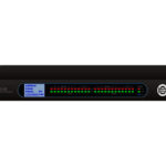
FRONT
ZONE X 1212

 GLOBAL STATUS LEDS
POWER = Device is switched on
NETWORK = Network connection active- INPUT & OUTPUT LEDS
White = Signal present
Red = Signal overload
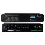
BACK
ZONE X 1212
- POWER SOCKET AND FUSE HOLDER
IEC mains socket with built-in fuse holder. A suitable power cable is included.
IMPORTANT NOTE: Only replace the fuse with a fuse of the same type and value. Pay attention to the imprint on the housing. In the event of repeated fuse failure, please contact an authorised service centre. - ON/OFF SWITCH
Rocker switch for switching the device on and off. - ETHERNET – USB – RESET
Communication expansion card with Ethernet connection for communication between the ZoneX processor and the host computer.
USB-C recovery port for firmware recovery and IP reset button. - ETHERNET – USB – RESET – DANTE
Communication expansion card with Ethernet + Dante (64 x 64 I/O) for communication between the ZoneX processor and the host computer and for integration into a Dante network. USB-C recovery port for firmware recovery and IP reset button. - GPO
8 GPO outputs (logic ports) with two selectable modes per output: LED (3 mA) or sink (300 mA). 3-pin terminal block connections (spacing 3.81 mm). Please also refer to the connection examples in these operating instructions (see GPI/O – CONNECTION EXAMPLES). - GPI
8 GPI inputs (logic ports), activation via ground contact. 3-pin terminal block connections (spacing 3.81 mm). Please also note the connection examples in these operating instructions (see GPI/O – CONNECTION EXAMPLES) - OUTPUTS
balanced audio outputs. 3-pin terminal block connections (3.81 mm spacing). - INPUTS
12 balanced mic/line audio inputs with separately switchable 48 V phantom power per channel. 3-pin terminal block connections (3.81 mm spacing).
CONNECT DEVICES
The ZoneX DSP processor and other control units utilise a network-based infrastructure and are set up and controlled by a computer and the Xilica Designer software.
REQUIREMENTS FOR OPERATION
- Computer
- Network interface (router, PoE switch)
- A router is required for IP assignment and fast, simple connection to your computer and connected control units. A PoE switch is required for control units without a local power supply.
- Ethernet cable. All wired connections are made via standard RJ45 Ethernet cables (Cat 5e or better).
A NETWORK CONNECTION BETWEEN THE HOST COMPUTER AND THE ZONEX PROCESSOR CAN BE ESTABLISHED IN THE FOLLOWING WAYS:
ROUTER WITH ACTIVATED DHCP SERVER (RECOMMENDED)
When using a router with an activated DHCP server, the ZoneX processor automatically obtains the IP address during start-up as soon as a connection is established. If additional control units/controllers from other manufacturers are integrated into the network, the use of a router and PoE switch is recommended. This combination provides a DHCP server and also enables the power supply to the connected devices. We recommend the use of Linksys routers and Netgear switches.
Note: Routers/switches with an activated DHCP server should always be switched on first and all Ethernet cables should be connected to the hardware before the connected hardware is switched on. This ensures that the IP addresses can always be assigned correctly.
- Switch on the router/switch first.
- Then connect the host computer to the router (DHCP activated) via an Ethernet cable.
- Connect the router to the ZoneX processor using an Ethernet cable.
- Connect the ZoneX processor to the power supply and switch it on.
NON-DHCP-BASED DIRECT CONNECTION OR INDIRECT CONNECTION VIA ETHERNET SWITCH
If the processor is connected directly to a computer or indirectly via a switch and no DHCP server is available, the connection cannot be established automatically.
Non-DHCP-based connections must therefore be configured manually. Further information can be found in the Xilica Designer help file or in the LD Systems ZoneX FAQ.

XILICA DESIGNER SOFTWARE
The Xilica Designer software not only enables detailed configuration of the ZoneX processor, but also provides access to programmable remote controllers and enables the setup and management of any Dante network devices as well as the integration of universal controllers from other manufacturers.
INSTALLATION UNDER MAC OS X
System Requirements:
- Mac OS X 10.8 or higher
- 1 GHz or faster processor
- 500 MB free hard disc space
- 1 GB graphics card
- 4 GB RAM
- Download the latest version of the Xilica Designer software from the LD Systems website www.ld-systems.com onto your computer.
- Open the downloaded .zip file.
- Then open the XilicaDesigner.mpkg file.
- An installation window will now appear. Follow the steps described individually.
 Once the installation process has been successfully completed, the following message appears in the installation window: “The installation wassuccessful.”.
- The Xilica Designer software is now installed.
INSTALLATION UNDER WINDOWS
System Requirements:
- Windows 7 or higher
- 1 GHz or faster processor
- 500 MB free hard disc space
- 1 GB graphics card
- 4 GB RAM
- Download the latest version of the Xilica Designer software from the LD Systems website www.ld-systems.com onto your computer.
- Open the downloaded .zip file.
- Then open the XilicaDesigner.exe file.
- An installation window will now appear. Click “Install” to continue.

- Wait until the installation process is complete. This may take a few minutes.
- Once the installation process has been successfully completed, Windows will ask you for permission to access the firewall. We recommend configuring the system so that communication in private networks such as home or company networks is authorised for Xilica Designer. Public networks can be included depending on requirements.
Select the desired options using the checkboxes and then click “Allow Access” to finalise the configuration.
- The Xilica Designer software is now installed.
START SOFTWARE
Locate the Xilica Designer software on your desktop or in the application folder. Double-click to start the software.
You can now create a new design project or open a design project and access the network view and the Dante view.

NETWORK VIEW
All processors and control units in the network are displayed in the network view. Here you will find device information such as connection status, computer IP address, device IP address, MAC address, device name, manufacturer and firmware version. 
The connected processor(s) should be visible in the network view. In the top left corner of the device block for the respective device, there is an indicator of the connection status.
- Green: The device is connected and ready for operation.
- Yellow: The device is connected and online, but not ready for operation. Move the mouse pointer over the network indicator and a window with the identified problems will open. (In most cases, the message should be that no device design is loaded.)
- Red: The device is not connected and offline. There is no communication between the Xilica Designer software and the device. Please check all cables and connections and make sure that the device is switched on. If the processor is currently performing a firmware upgrade or restarting, this may be a temporary interruption.
- From time to time you may see an exclamation mark (!). This indicates that a firmware upgrade is available. Normally, this does not require immediate action unless the project file contains updated models that the previous firmware does not support. Further information can be found in the Xilica Designer help file or in the LD Systems ZoneX FAQ.
FIRMWARE UPGRADE
- Please note that although using an older software version with newer firmware or using newer software with older firmware generally works, the range of functions may be limited or the functionality may not be ensured in all cases.
We recommend that you always update the software and firmware to the latest version. - Before you start, please check the software and firmware versions.
- To check the current device firmware version, first make sure that your device is switched on and online. In the network view, devices for which a firmware upgrade is available are marked with a yellow triangle with an exclamation mark. The device firmware version is also listed in the device block for the respective device.
- The current software version is displayed when you click About in the menu at the top of the software window.
PERFORM FIRMWARE UPGRADE
Save all design files of the device to your computer, as all data and programming in the device will be deleted during the upgrade.
Once the firmware upgrade is complete, the design file can be reloaded into the device.
- To perform a firmware upgrade, the device must be online and ready for operation.

- The latest firmware version for the corresponding Zone X model is available for download on the LD Systems website www.ld-systems.com
- In the network view, right-click on the device block and select “Firmware Upgrade”.
 A warning will then appear that all data will be deleted from your device during the firmware upgrade. Confirm with “OK” to continue.
- A drop-down menu now appears, which you can use to directly select the desired firmware file from a file system or a firmware version previously downloaded via the “Device Firmware Manager” (in the “Device Management” menu). Confirm with “OK” and navigate to the folder in which you have saved the new firmware file. Select the file and click “Open”.

- A status bar in the device window shows the progress of the firmware upgrade.

- DO NOT SWITCH OFF THE DEVICE OR DISCONNECT IT FROM THE COMPUTER. If the device is switched off or disconnected from the computer during a firmware upgrade, the processor may no longer function. In this case, the firmware must be restored (“USB Firmware Recovery”).
- As soon as the firmware file has been successfully loaded into the device, it restarts automatically and the internal data is updated. This may take a few minutes. During this time, the network indicator changes to RED and the device is in offline mode.
- When the firmware upgrade has been completed, the green “ON” is displayed again.

- NOTE: The yellow field with the message “No Data” means that no design has yet been loaded into the device.
PROJECT VIEW
A new project can be created in two different ways:
AUTO CONFIGURATION
If your device is listed in the network view, select it and click Create New Project from Selected Device(s) in the top right corner. This automatically takes you to the project view where you can select a design template.  EMPTY PROJECT
The second option is to create a new project via File > New Project.
If you start with an empty project, Xilica Designer first asks which DSP series you are using. As the ZoneX is based on the Solaro DSP series, select Solaro Series.

- COMPONENT LIBRARY” MENU
In this menu you will find a list of devices and design modules for use in your project. Locate the ZoneX processor under LD Systems > Processors. - WORKSPACE
The workspace provides space for creating and configuring devices. - OBJECT PROPERTY” MENU
In this menu, you can customise the object properties for the respective design.
DESIGN
In this case, only one DSP hardware block is required for demonstration purposes, but a design can also include several DSP hardware objects. Project designs can be created offline (without connected hardware) and can be loaded into your devices later.
- Drag and drop the desired DSP module, in this case Zone X1212, from the “Component Library” into the workspace.

- A selection window for the design template (Select Design Template) appears. Select one of the templates on offer and you will receive a brief description and an overview of the most important features of this design template. Select a suitable template for your project and confirm with OK.
Detailed descriptions of the various templates can be found in the LD Systems ZoneX FAQ. - The ZoneX processor is configured accordingly.

- Select the ZoneX module to highlight it. The device properties can now be customised in the “Object Property” menu on the right. Note: The object properties are device-dependent and vary depending on the selected object.

- Double-click the ZoneX module to open the schematic design overview. In this example, the “Global Dante” template is selected. You can change the window size by dragging the corners of the window.

- All DSP modules can be edited offline. Double-click to open the desired module. You can then adjust the settings for the DSP module to the requirements of your project.

In this example, phantom power has been activated in the input settings and the gain settings for the first two channels have been adjusted. We also renamed the first four channels in the audio input module and finally edited input channel 1. - Now route the input signals to the corresponding outputs by double-clicking the Main Matrix Mixer module. These can also be processed again with an output processing module.

- If you have changed settings offline, save your project in the desired location by clicking File > Save As. If you have changed an existing project file, save it with File > Save. Click the “Save” icon in the top right corner of the workspace to do the same.

It is advisable to save backups of the project files externally.
The file extension (name extension) for saved project files is .pjxml.
ONLINE OPERATION
When you switch to online mode, the design file is loaded into the connected device(s) and you can make adjustments in real time.
In this case, all devices must be connected and online (green “ON” indicator in the network view).  To switch to online mode, the device module must be assigned to the physical hardware.
- In the project view, select the device module that you want to assign.
- Right-click the device module and select Map to Physical Device.
- The recognised devices are now listed with their Mac addresses. If several identical devices are integrated in the network, they can be identified] by their Mac addresses. The Mac addresses for the individual devices can be found in the network view.
It is very important that the name of the device block in the design file corresponds exactly to the unit in the network view, otherwise the design cannot be loaded into the corresponding hardware.
If everything is assigned, the colour of the module changes to solid grey and the Mac address of the device is displayed at the bottom of the device module.
- Now click Load Design to Device(s) at the top of the workspace.

- A window will appear in which you can tick the devices to which you want to load your design. Confirm with OK.

Switching to online mode can take a few minutes. Please do not interrupt the process! The progress of the process is displayed as a percentage bar at the top of the window. As soon as the workspace appears in a solid grey, you are in online mode and the design menus are no longer available.
 - If you want to change settings in real time, you can either double-click the DSP module in the project view or the device block in the network view to see the schematic representation for the respective device.

- Double-click the desired DSP module or I/O block to change settings in real time.

You can switch back to design mode at any time using the Go Back to Design Mode button at the top of the workspace. You will be asked whether you want to transfer the changes you have made online to the project design.

- Confirm with Yes to transfer the online settings to the project.
- Click No to return to the previous design file.
- After transferring online settings to a project, the original project file is overwritten with the File > Save command.
- If you select File > Save As, a new project file is created and saved.
- It is advisable to save a backup of the project file(s) externally.
GPI/O – CONNECTION EXAMPLES 8 LOGIC INPUTS (BINARY INPUTS, GPI)
 Each GPI offers two switching states (via software)
- Two different presets can be controlled
- Opening and closing the contacts
8 LOGIC OUTPUTS (BINARY OUTPUTS, GPO)
2 output modes are available:
- LED (3 mA)
- Sink to ground (300 mA)

TECHNICAL SPECIFICATIONS
- Product number LDZONEX1212 / LDZONEX1212D
- Product type DSP audio matrix for fixed installation
General data
- Audio inputs 12 balanced line outputs
- Audio outputs 12 balanced line outputs
- Logic inputs 8 GPI – Activation via short to ground
- Logic outputs 8 GPO modes: LED (3 mA) or sink (300 mA)
- Connections 3-pin terminal block, spacing 3.81 mm, inputs / outputs, Ethernet RJ45, service connection MicroUSB type-C
- Display indicators Inputs 1 – 12 and outputs 1 – 12: White signal LED, network, power
- Controls, front No
- Controls, rear IP Reset, Power On/Off
- Expansion slot Ethernet + Dante (ZONEX1212D), For Ethernet (ZONEX1212)
- Cooling Convection, passive
- Power supply Wide-range switching power supply
- Mains connection 3-pin IEC mains connection (IEC socket)
- Operating voltage 90 – 240 V AC; 50/60 Hz
- Input fuse (mains) T2.5 A L / 250 V
- Inrush current mains OFF-ON 21 A
- Power consumption in idle mode 23 W
- Max. power consumption 60 W
- Operating temperature 0°C – 40°C; < 60% humidity
- Width 19″ rack (483 mm)
- Height 1 U (44.5 mm)
- Depth 315 mm (including terminal blocks)
- Weight 4 k
Performance specifications


MANUFACTURER´S DECLARATIONS
MANUFACTURER‘S WARRANTY & LIMITATIONS OF LIABILITY
You can find our current warranty conditions and limitations of liability at: https://cdn-shop.adamhall.com/media/pdf/MANUFACTURERS-DECLARATIONS_LD_SYSTEMS.pdf To request warranty service for a product, please contact Adam Hall GmbH, Adam-Hall-Str. 1,
61267 Neu Anspach / Email: Info@adamhall.com / +49 (0)6081 / 9419-0.
CORRECT DISPOSAL OF THIS PRODUCT
(valid in the European Union and other European countries with a differentiated waste collection system) This symbol on the product, or on its documents indicates that the device may not be treated as household waste. This is to avoid environmental damage or personal injury due to uncontrolled waste disposal. Please dispose of this product separately from other waste and have it recycled to promote sustainable economic activity. Household users should contact either the retailer where they purchased this product, or their local government office, for details on where and how they can recycle this item in an environmentally friendly manner. Business users should contact their supplier and check the terms and conditions of the purchase contract. This product should not be mixed with other commercial waste for disposal.
FCC STATEMENT
- This device complies with Part 15 of the FCC Rules. Operation is subject to the following two conditions:
- This device may not cause harmful interference, and
- This device must accept any interference received, including interference that may cause undesired operation
- any Changes or modifications not expressly approved by the party responsible for compliance could void the user‘s authority to operate the equip-ment.
- NOTE: This equipment has been tested and found to comply with the limits for a Class B digital device, pursuant to Part 15 of the FCC Rules. These limits are designed to provide reasonable protection against harmful interference in a residential installation.
- This equipment generates uses and can radiate radio frequency energy and, if not installed and used in accordance with the instructions, may cause harmful interference to radio communications. However, there is no guarantee that interference will not occur in a particular installation. If this equipment does cause harmful
- interference to radio or television reception, which can be determined by turning the equipment off and on, the user is encouraged to try to correct the interference by one or more of the following measures:
- Reorient or relocate the receiving antenna.
- Increase the separation between the equipment and receiver.
- Connect the equipment into an outlet on a circuit different from that to which the receiver is connected.
- Consult the dealer or an experienced radio/TV technician for help.
FCC RADIATION EXPOSURE STATEMENT
- This equipment complies with FCC radiation exposure limits set forth for an uncontrolled environment. This equipment should be installed and operated with minimum distance 20cm between the radiator & your body
![]() CE COMPLIANCE
CE COMPLIANCE
- Adam Hall GmbH states that this product meets the following guidelines (where applicable):
- R&TTE (1999/5/EC) or RED (2014/53/EU) from June 2017
- Low voltage directive (2014/35/EU)
- EMV directive (2014/30/EU)
- RoHS (2011/65/EU)
- The complete declaration of conformity can be found at www.adamhall.com
- Furthermore, you may also direct your enquiry to info@adamhall.com
EU DECLARATION OF CONFORMITY
- Hereby, Adam Hall GmbH declares that this radio equipment type is in compliance with Directive 2014/53/EU.
- The full text of the EU declaration of conformity is available at the following
- internet address: www.adamhall.com/compliance
- Printing errors and mistakes, as well as technical or other changes are reserved!
Documents / Resources
 |
LDSystems ZONE X 1212 LDZONEX1212, LDZONEX1212D Hybrid Architecture DSP Matrix [pdf] User Manual ZONE X 1212 LDZONEX1212 LDZONEX1212D Hybrid Architecture DSP Matrix, ZONE X 1212 LDZONEX1212 LDZONEX1212D, Hybrid Architecture DSP Matrix, Architecture DSP Matrix, DSP Matrix, Matrix |