![]() Precision Benchtop
Precision Benchtop
Router Table
OWNER’S MANUAL
Item# PRS2100
PRS2100 Precision Benchtop Router Table
Tools Required:
- #2 Square Driver Bit (Included)
- 1/8-in. Hex Wrench (Included)
- #2 Phillips screw driver
- Flat-blade screw driver
- 7/16-in. Socket Wrench
- Double-faced Tape
- Drill Press or Hand Drill
- Drill Bits
- Metal Ships
General Safety Instructions
![]() WARNING When using electric tools, always follow the safety precautions below to reduce the risk of fire, electric shock, and personal injury.
WARNING When using electric tools, always follow the safety precautions below to reduce the risk of fire, electric shock, and personal injury.
Read all these instructions before attempting to operate this product. SAVE THESE INSTRUCTIONS.
- Work area safety
a) Keep work area clean and well lit. Cluttered or dark areas invite accidents.
b) Don’t use power tools in a dangerous environment. Don’t use power tools in damp or wet locations, or expose them to rain.
c) Do not operate power tools in explosive atmospheres, such as in the presence of flammable liquids, gases or dust. Power tools create sparks that can ignite the fumes or dust.
d) Keep children and bystanders away while operating a power tool. Distractions can cause you to lose control.
e) Make your workshop child proof. Use padlocks, master switches, or remove starter keys. - Electrical safety
a) Ground electric tools. If the tool is equipped with a three-prong plug, it must be plugged into a grounded three-hole electrical outlet. If the proper outlet is not available, have one installed by a qualified electrician. Never remove the third prong or modify the provided plug in any way.
b) Do not expose power tools to rain or wet conditions. Water entering a power tool increases the risk of electric shock.
c) Do not abuse the cord. Never use the cord for carrying, pulling or unplugging the power tool. Keep cord away from heat, oil, sharp edges or moving parts. Damaged or entangled cords increase the risk of electric shock.
d) Use a proper extension cord and make sure it is in good condition. When using an extension cord, be sure to use one heavy enough to carry the current your power tool draws. An undersized cord causes a drop in line voltage resulting in loss of power and overheating. Table 1 on the following page shows the correct cord gauge to use depending on cord length and tool nameplate ampere rating. If in doubt, use the next heavier gage. The smaller the gage number, the heavier the cord.
e) When operating electric tools, avoid body contact with grounded or earthed surfaces such as pipes, radiators, kitchen ranges, and refrigerators. Contact with a grounded surface increases the risk of electric shock. - Personal safety
a) Stay alert, watch what you are doing and use common sense when operating a power tool. Do not use a power tool while you are tired or under the influence of drugs, alcohol or medication. A moment of inattention while operating power tools can result in serious personal injury.
b) Always wear safety glasses. Everyday eyeglasses are not safety glasses. Safety glasses have specially constructed lenses, frames, and side shields.
c) Use safety equipment. Use a face or dust mask when the cutting operation is dusty. Safety equipment such as a dust mask, non-skid safety shoes, hard hat, or hearing protection used for appropriate conditions reduces personal injuries.
d) Avoid accidental starting. Make sure the switch is in the off-position before plugging in. Carrying power tools with your finger on the switch or plugging in power tools that have the switch on invites accidents.
e) Remove any adjusting key or wrench before turning the power tool on. A wrench or a key left attached to a rotating part of the power tool can result in personal injury.
f) Do not overreach. Keep proper footing and balance at all times. This enables better control of the power tool in unexpected situations.
g) Secure workpieces. Use clamps or a vise to hold work when practical. This is safer than using your hand and it frees both hands to operate the tool.
h) Never stand on the machine. Serious injury can occur if the tool tips or if the cutting tool is unintentionally contacted.
i) Dress properly. Do not wear loose clothing or jewelry. Keep your hair, clothing and gloves away from moving parts. Loose clothes, jewelry or long hair can be caught in moving parts. Roll up long sleeves to the elbow. Wear protective hair covering to contain long hair.
j) If devices are provided for the connection of dust extraction and collection facilities, ensure these are connected and properly used. Use of these devices reduces dust-related hazards. - Power tool use and care
a) Keep guards in place and in working order.
b) Do not force the power tool. Use the correct power tool for your application. The tool will do the job better and safer at the feed rate for which it was designed.
c) Use right tool or accessory. Don’t force a tool or attachment to do a job for which it was not designed.
d) Do not use the power tool if the switch does not turn it on and off. Any power tool that cannot be controlled with the switch is dangerous and must be repaired.
e) Disconnect the plug from the power source and/or the battery pack from the power tool before making any adjustments, changing accessories, or storing power tools. Such preventive safety measures reduce the risk of starting the power tool accidentally.
f) Never leave tool running unattended. Turn power off. Do not leave tool until it comes to a complete stop.
g) Store idle power tools out of the reach of children and do not allow persons unfamiliar with the power tool or these instructions to operate the power tool. Power tools are dangerous in the hands of untrained users.
h) Maintain power tools. Check for misalignment or binding of moving parts, breakage of parts and any other condition that can affect power tool operation. If damaged, have the power tool repaired before use. Many accidents are caused by poorly maintained power tools.
i) Keep cutting tools sharp and clean. Properly maintained cutting tools with sharp cutting edges are less likely to bind and are easier to control.
j) Use the recommended speed for the cutting tool or accessory and workpiece material.
k) Only use parts and accessories recommended by the manufacturer. Consult the owner’s manual for recommended accessories. Using improper accessories can cause personal injury.
l) Use the power tool, accessories, and tool bits in accordance with these instructions and in the manner intended for the particular type of power tool, taking into account the working conditions and the work to be performed. Use of the power tool for operations different from those intended can result in a hazardous situation. - Service
a) Have your power tool serviced by a qualified repair person using only identical replacement parts. This ensures that the safety of the power tool is maintained. - Safety Instructions specific to operating the Precision Benchtop Router Table.
a) Read, understand, and follow your router manufacturer’s safety warnings and instructions.
b) Disconnect the router from power before making adjustments. Never adjust the fence, plate, reducing rings, or any part of the router or router table while the router is running.
c) Place the router table on a flat surface to prevent tipping or sliding. Never stand on the router table.
d) Do not attempt to rout warped, twisted, or bowed workpieces. All workpieces must have flat faces and square edges.
e) Do not attempt to rout very large workpieces on a router table. Very large workpieces can be difficult to control and can cause the router table to tip over.
f) Only use router bits in your router. Never use tools such as carving burrs, mounted abrasives, wire wheels, or drill pits, even if the shanks match the diameter of the router collet.
g) Wear gloves when handling router bits. Cutting edges are sharp.
h) Never use dirty, dull, or damaged router bits. Remove wood-resin build-up with a cleaner specifically formulated for cutting tools. Have dull bits sharpened by a qualified person. Discard damaged bits.
i) Make sure at least 75% of the router-bit shank length is securely held in the router collet. To ensure a secure hold, leave 1⁄16″ to 1⁄8″ (2mm-3mm) between the end of the bit shanks and the bottom of the collet.
j) Use the insert-plate reducing ring with the smallest opening that allows the bit to pass through it. A large gap around the bit can allow the workpiece to tip into the bit and kick back.
k) Position the fence faces as close as possible to the bit. Turn the bit by hand to check for interference. Firmly tighten the fence-face T-knobs before routing.
l) Adjust router speed to match the diameter of the bit. Reduce router speed when using large-diameter bits. See Table 2 for recommended router speeds.
m) Make sure the router motor is securely clamped in the base before starting the router.
n) Always support the workpiece with the fence or start pin. Only use the starter pin with router bits that have a guide bearing.
o) When using the fence, always position the bit guard over the router bit and as close to the workpiece surface as possible.
p) Never remove a large quantity of stock in one cut. Make several progressively deeper cuts, adjusting the router bit or fence position between cuts.
q) Keep hands away from the rotating bit and your body out of the path of the cut. Always use the bit guard, Use push sticks, push blocks, and feather boards whenever possible, especially when routing narrow workpieces. Turn off the router before clearing parts of scrap.
r) Avoid awkward hand positions, where a sudden slip could cause contact with the rotating bit. Never overreach.
s) Avoid routing small parts. Rout the profile on a large workpiece and then cut the part to final size from the large workpiece. If you must rout a small part, build an appropriate jig or hold the part with a wood handscrew clamp.
t) Make sure the workpiece is clear of the bit and the bit comes to a complete stop before adjusting the workpiece position. Never start the router with the workpiece in contact with the bit.
u) Avoid kickbacks. Kickbacks occur when the workpiece binds or lifts off the table while being routed, causing it to be thrown back toward the operator. To avoid kickbacks and potential injury, use sharp bits, keep the machine aligned and maintained properly, and adequately support the workpiece. Do not attempt to rout workpieces that are twisted, warped, or bowed, or that have loose knots.
v) Feed the workpiece against (not with) the bit rotation. The bit can grab a workpiece fed with the rotation of the bit, violently eject it from the router table, and can cause your hand to contact the bit.
w) Never trap a workpiece between the bit and the fence. When forming a profile on the straight edge of a workpiece, always rout with the bit housed in the fence and the edge of the workpiece against the fence.
x) Whenever routing a profile in which material is not being removed below a protruding portion of the bit, or a part of the profile is trapped between cutters above and below, take extra precautions to prevent the workpiece from lifting off the table surface during routing. A workpiece lifting off the table can kick back and cause serious personal injury. When routing these profiles, it is especially important to use straight, flat stock and avoid warped, bowed, or twisted stock.
y) Periodically check the tightness of fasteners and adjustment and locking knobs and the alignment of the fence. Loose fasteners and knobs and a misaligned fence can cause personal injury.
z) This router table is designed for a specific application. Do not modify and or use it for any other application. If you have questions relative to the application of the router table, DO NOT use it until you have contacted Kreg Tool Company and have been advised accordingly.
Guidelines for extension cord use
Extension cords are only to be used for temporary purposes. They do not replace the need for installation of outlets and proper wiring where necessary.
In the shop and on construction sites:
- Extension cords with an equipment grounding conductor must be used at all times.
- Extension cords must be protected from damage, and not run through doorways or windows where the doors or windows can close, causing damage to the cord.
- Extension cords must be a minimum of 16 AWG and be rated for the equipment in use.
- Extension cords must be periodically inspected to ensure that the insulation and conductivity of the wires are not compromised.
- Extension cords should not be run through water or allowed to have connections that may be exposed to accumulated water.
TABLE 1
| Nameplate Amperes @120 V | Extension Cord Length | |||||
| 25′ | 50′ | 75′ | 100′ | 150′ | 200′ | |
| Recommended Wire Gauge | ||||||
| 0 -5 | 16 | 16 | 16 | 14 | 12 | 12 |
| 5.1 – 8 | 16 | 16 | 14 | 12 | 10 | NR |
| 8.1 -12 | 14 | 14 | 12 | 10 | NR | NR |
| 12.1 – 16 | 12 | 12 | NR | NR | NR | NR |
NR – Not Recommended
TABLE 2
| Recommended Router Bit Speeds | |
| Bit Diameter | Maximum Speed (RPM) |
| Up to 1″ (25mm) | 24,000 |
| 1¼″ to 2″ (32mm-51mm) | 18,000 |
| 2¼″ to 2½″ (57mm-64mm) | 16,000 |
| 3″ to 3½″ (76mm-89mm) | 12,000 |
Always follow bit manufacturer’s speed recommendations. Some bit designs require specific speeds for safety or performance.
![]() WARNING: This product can expose you to chemicals including Acrylonitrile and other chemicals, which are known to the State of California to cause cancer and reproductive harm. For more information go to www.P65Warnings.ca.gov.
WARNING: This product can expose you to chemicals including Acrylonitrile and other chemicals, which are known to the State of California to cause cancer and reproductive harm. For more information go to www.P65Warnings.ca.gov.
![]() WARNING: Drilling, sawing, sanding or machining wood products can expose you to wood dust, a substance known to the State of California to cause cancer. Avoid inhaling wood dust or use a dust mask or other safeguards for personal protection. For more information go to www.P65Warnings.ca.gov/wood.
WARNING: Drilling, sawing, sanding or machining wood products can expose you to wood dust, a substance known to the State of California to cause cancer. Avoid inhaling wood dust or use a dust mask or other safeguards for personal protection. For more information go to www.P65Warnings.ca.gov/wood.
Benchtop Router Table Parts List
| # | Description | Part # | Quantity |
| 1 | LEGS | RT10180-2 | 4 |
| 2 | 1″ COARSE-THREAD SCREWS | * | 4 |
| 3 | RUBBER FEET | * | 4 |
| 4 | FOOT SUPPORTS | * | 4 |
| 5 | SHORT RAILS | RT10180-1 | 2 |
| 6 | LONG RAILS | ** | 2 |
| 7 | BRACES | ** | 2 |
| 8 | 1⁄4-20 X 1⁄2″ FLATHEAD CARRIAGE BOLTS | * | 16 |
| 9 | 1⁄4″ FLANGE HEX NUTS | * | 16 |
| 10 | TABLE TOP | NK9205 | 1 |
| 11 | MITER TRACK | NK8036 | 1 |
| 12 | 5MM X 20MM FLATHEAD SCREWS | NK8023 | 3 |
| 13 | INSERT PLATE LEVELERS | RT10100 | 4 |
| 14 | 1 1⁄4″ COARSE-THREAD SCREWS | SML-C125 | 12 |
| 15 | 1⁄8″ HEX WRENCH | AW18 | 1 |
| 16 | 1⁄4-20 X 1 1⁄2″ SOCKET-HEAD SET SCREWS | RT10111 | 8 |
| 17 | 3⁄4″ COARSE-THREAD SCREWS | * | 16 |
| 18 | INSERT PLATE | NK8840 | 1 |
| 19 | 1⁄4-20 X 1 3⁄4″ PHILLIPS PANHEAD MACHINE SCREWS | RT10112 | 4 |
| 20 | 1⁄4-20 X 3⁄4″ SOCKET-HEAD SET SCREW | DK1522 | 1 |
| 21 | STARTING PIN | RT10108 | 1 |
| 22 | FENCE EXTRUSION | NK8010 | 1 |
| 23 | VACUUM PORT | RT10151 | 1 |
| 24 | 10-32 X 3⁄8″ PANHEAD MACHINE SCREWS | RT10153 | 2 |
| 25 | 48″ CENTER-READING TAPE | RT10140 | 1 |
| 26 | FENCE FACES | NK9207 | 2 |
| 27 | 1⁄4-20 X 1 1⁄2″ FLATHEAD MACHINE SCREW | RT10152 | 4 |
| 28 | 1⁄4″ FLAT WASHER | DK1504 | 6 |
| 29 | T-KNOBS | DK1313 | 6 |
| 30 | BIT GUARD | RT10133 | 1 |
| 31 | 1⁄4-20 X 1 1⁄4″ T-BOLTS | FT4212 | 2 |
| 32 | SPACERS | RT10134 | 2 |
| 33 | FENCE-LOCK BASES | NK8212 | 2 |
| 34 | FENCE-LOCK HANDLES | NK8204 | 2 |
| 35 | 1⁄4-20 X 2 1⁄2″ PHILLIPS PANHEAD MACHINE SCREWS | DB5253 | 2 |
| 36 | FENCE-LOCK ANCHORS | NK8009 | 2 |
| 37 | LOCK NUTS | NK8355 | 2 |
| 38 | JOINTING RODS | RT10149 | 2 |
| 39 | 1″ REDUCING RING | NK7773 | 1 |
| 40 | GUIDE BUSHING REDUCING RING | NK7775 | 1 |
| 41 | 25⁄8″ REDUCING RING | NK7774 | 1 |
| 42 | RING WRENCH | NK8003 | 1 |
*Included in RT10180-2 parts box
**Included in RT10180-1 parts box
Benchtop Router Table Assembly Instructions

Step 1
Open inner-pack box RT10180-2 and remove the legs (#1) and hardware pack. On each leg, insert a 1″ coarse-thread screw (#2) through a rubber foot (#3), through the hole in the bottom of each leg, and then drive the screw into the foot support (#4) pilot hole. Be careful not to strip out the foot support pilot holes by over-tightening the screws.
Step 2
Open inner-pack box RT10180-1 and remove the short rails (#5), long rails (#6), and braces (#7). Bolt a short rail to each pair of legs (#1) using four ¼-20 x ½″ flathead carriage bolts (#8) and four ¼″ flange hex nuts (#9) per rail. At this time, only finger-tighten the nuts.
Now join the leg/short rail assemblies by bolting the long rails to the legs. Again, only finger-tighten the nuts.
Step 3
The table top (#10) is shipped with the miter track (#11) in place, but not fastened. Secure the miter track with three 5mm flathead screws (#12), driving them into the pre-drilled holes in the table top.

Place the table top upside down on your work bench and position an insertplate leveler (#13) in each corner of the opening in the table top, mating the curve on the raised portion of the leveler with the radius corner of the opening. The holes in the leveler align with pilot holes in the table-top.
Fasten each leveler to the tabletop with three 1¼″ coarse-thread screws (#14).
Using the ⅛″ hex wrench (#15), drive a ¼-20 x 1½″ socket-head set screw (#16) into the outside holes in each leveler, threading them in from the bottom until the tips are ⅜″ below the table surface.
Step 4
Position the legs/rails assembly on the bottom face of the router table top with the Kreg logo facing the front. (The miter-gauge track is at the front edge of the table top.) Align the holes in the top flanges of the legs with the pilot holes in the table top. Fasten the legs to the top with eight ¾″ coarse-thread screws (#17). Be careful not to strip out the pilot holes by over-tightening the screws.
Tighten all sixteen nuts on the leg/rail assembly.
Position the braces (#7) on the bottom face of the table top (#10) along the long edges. Align the holes in the braces with the pilot holes in the table top. Fasten the braces to the top with eight ¾″ coarse-thread screws (#17).

Step 5
The included insert plate has center points molded into the bottom face for drilling mounting holes for the following routers: Pattern 1 (three holes): Bosch 1617 and 1618; DeWalt 616 and 618; Hitachi M12VC; Makita 1100; Milwaukee 5616 and 5624; Porter-Cable 690, 890, 7529, 97529, and 8529; and Ridgid 2930 Combo Kit. Pattern 2 (four holes): Milwaukee 5625-20; Porter-Cable 7518, 7519, 7538, and 7539; and Triton TRA001 and MOF001. Drill holes and counterbores or countersinks to accommodate the mounting screws supplied with the router. For routers equipped with a built-in lift system, use the router sub-base as a guide for the location and size of the access hole and as a drilling guide.

For routers not covered by Pattern 1 or Pattern 2 follow the instructions below.
![]() ATTENTION To view a free video that shows you how to drill your insert plate, go to www.kregtool.com. You also can have Kreg do the drilling for a fee. For complete information, go to www.kregtool.com/plateprogram.
ATTENTION To view a free video that shows you how to drill your insert plate, go to www.kregtool.com. You also can have Kreg do the drilling for a fee. For complete information, go to www.kregtool.com/plateprogram.
Place the insert plate (#18) on your workbench with the target pattern facing up. Remove the sub-base from your router and select a drill bit that fits the mounting holes. If your router is equipped with a built-in lift system, select a bit that fits the lift-access hole. Apply several small pieces of double-faced tape to the insert plate. Now, center the sub-base on the plate, using the concentric arcs of the target pattern as guides. Keep in mind where you want the router controls positioned. Make sure that none of the holes you are about to drill align with the threaded hole for the start pin. Press the sub-base firmly onto the insert plate.

Using the holes in the sub-base as guides, drill the holes in the insert plate with a drill press or hand drill. Performing this operation on a drill press ensures that the holes are perpendicular to the plate. Before drilling, securely clamp the insert plate to your drill-press table or bench to prevent it from moving as you drill. Whether you use a drill press or hand drill, place a scrap piece of wood under the insert plate to reduce chipping as the drill bit passes through the plate.

With the holes drilled, remove the sub-base from the insert plate. Flip the plate over and countersink the mounting holes so the machine screw heads sit slightly below the plate surface when tightened down. Store the router sub-base in a convenient place. You will need it when you remove your router from the router table for handheld routing.
Step 6
Attach the router base to the insert plate, using the screws that attached the sub-base to the router base. Depending on the thickness of your router sub-base, it may be necessary to purchase longer screws. Make certain that the screws are long enough to fully thread into the router base. If you are mounting a fixed-base router, install the motor unit in the router base.

Place the insert plate with the router attached in the table top opening, resting it on the eight set screws (#16) in the plate levelers (#13). Using the hex wrench (#15), adjust the set screws from under the table to align the surfaces of the plate and the table. Check the alignment with a steel ruler or the edge of a jointed board. Make sure all eight set screws are in equal contact with the insert plate. Thread the four ¼-20 x 1¾″ machine screws (#19) through the countersunk holes in the insert plate and into the center hole on each leveler and snug them down. The machine screws and set screws apply pressure in opposing directions, locking the insert plate in place. Some loosening or tightening of the lock down screws and set screws may be necessary to fine-tune the alignment.
Thread the ¼-20 x ¾″ set screw (#20) into the bottom of the starting pin (#21) and tighten the assembly with a flat-blade screw driver and ⅛″ hex wrench (#15). When ready for use, thread the starting pin assembly into the threaded hole in the insert plate and tighten it.
Step 7
Mount the vacuum port (#23) to the fence extrusion (#22) using two #10-32 x ⅜″ Phillips pan head machine screws (#24).

Step 8
Using a tape measure and pencil, locate and mark the center point of the top edge of the fence extrusion (#22). Position the zero mark of the self-adhesive center-reading tape (#25) at the pencil mark and remove the protective backing as you adhere the tape to the extrusion. With the tape adhered, trim the excess flush with each end of the extrusion with metal snips.

Step 9
Install the two fence faces (#26) using two ¼-20 x 1½″ flat head machine screws (#27) inserted through the front of each fence face. Secure the machine screws at the back with two ¼″ flat washers (#28) and two T-knobs (#29) for each fence face.

Step 10
Assemble the bit guard (#30) using two ¼-20 x 1¼″ T-bolts (#31), two spacers (#32), two ¼″ flat washers (#28), and two T-knobs (#29), as shown. Slide the T-bolt heads into the T-slot at the top front edge of the fence extrusion and tighten the knobs.

Step 11
Assemble the ¼-turn fence locks using the fence-lock bases (33), fence-lock handles (34), ¼-20 x 2½″ Phillips panhead machine screws (35), fence-lock anchors (36), and lock nuts (37). Slip the machine screws (35) through the fence-lock handles (34) and fence-lock bases (33). Drop the handle/base/ machine screw assemblies through the holes in the base flange of the fence extrusion and the keyhole slots in the router table top. The flat edges of the base stems face the back of the fence and the handles point away from the back of the fence. Slide the fence-lock anchors (36) onto the machine screws from underneath the table with the anchor ″fingers″ in the table-top slots. With the nylon inserts in the lock nuts (37) facing down, thread the nuts onto the machine screws. Lower the fence-lock anchors onto the lock nuts, housing the nuts in the tapered hexagonal recesses in the anchors. Tighten the machine screws with a screw driver to draw the lock nuts into the fence-lock anchors. Once the nuts are fully seated in the anchors, they will not drop out.

Loosen the machine screws and position the fence-lock handles (34) pointing away from the fence and angled 45 degrees to the left [viewed from the back of the fence]. This is the locked position for the handles. To adjust fence-lock tension, tighten the machine screws with a screw driver until the clamps are tight enough to hold the fence in place. Rotate the handles ¼-turn counterclockwise to release the fence.
![]() WARNING Periodically check the fence locks to make sure they have not loosened with use. Tighten the machine screws (35) as needed.
WARNING Periodically check the fence locks to make sure they have not loosened with use. Tighten the machine screws (35) as needed.
Step 12
To store the jointing rods (38), slide them into the round channel at the back edge of the base flange of the fence extrusion. For instructions on how to use these rods for jointing on your router table, see the Jointing under the section USING YOUR ROUTER TABLE.

Safety Instructions Specific To Operating The Precision Benchtop Router Table
![]() WARNING When using electric tools, always follow the safety precautions below to reduce the risk of fire, electric shock, and personal injury.
WARNING When using electric tools, always follow the safety precautions below to reduce the risk of fire, electric shock, and personal injury.
Read all these instructions before attempting to operate this product.
SAVE THESE INSTRUCTIONS
a) Read, understand, and follow your router manufacturer’s safety warnings and instructions.
b) Disconnect the router from power before making adjustments. Never adjust the fence, plate, reducing rings, or any part of the router or router table while the router is running.
c) Place the router table on a flat surface to prevent tipping or sliding. Never stand on the router table.
d) Do not attempt to rout warped, twisted, or bowed workpieces. All workpieces must have flat faces and square edges.
e) Do not attempt to rout very large workpieces on a router table. Very large workpieces can be difficult to control and can cause the router table to tip over.
f) Only use router bits in your router. Never use tools such as carving burrs, mounted abrasives, wire wheels, or drill pits, even if the shanks match the diameter of the router collet.
g) Wear gloves when handling router bits. Cutting edges are sharp.
h) Never use dirty, dull, or damaged router bits. Remove wood-resin build-up with a cleaner specifically formulated for cutting tools. Have dull bits sharpened by a qualified person. Discard damaged bits.
i) Make sure at least 75% of the router-bit shank length is securely held in the router collet. To ensure a secure hold, leave 1⁄16″ to 1⁄8″ (2mm-3mm) between the end of the bit shanks and the bottom of the collet.
j) Use the insert-plate reducing ring with the smallest opening that allows the bit to pass through it. A large gap around the bit can allow the workpiece to tip into the bit and kick back.
k) Position the fence faces as close as possible to the bit. Turn the bit by hand to check for interference. Firmly tighten the fence-face T-knobs before routing.
l) Adjust router speed to match the diameter of the bit. Reduce router speed when using large-diameter bits. See the Table at right for recommended router speeds.
m) Make sure the router motor is securely clamped in the base before starting the router.
n) Always support the workpiece with the fence or start pin. Only use the starter pin with router bits that have a guide bearing.
o) When using the fence, always position the bit guard over the router bit and as close to the workpiece surface as possible.
p) Never remove a large quantity of stock in one cut. Make several progressively deeper cuts, adjusting the router bit or fence position between cuts.
q) Keep hands away from the rotating bit and your body out of the path of the cut. Always use the bit guard, Use push sticks, push blocks, and feather boards whenever possible, especially when routing narrow workpieces. Turn off the router before clearing parts of scrap.
r) Avoid awkward hand positions, where a sudden slip could cause contact with the rotating bit. Never overreach.
s) Avoid routing small parts. Rout the profile on a large workpiece and then cut the part to final size from the large workpiece. If you must rout a small part, build an appropriate jig or hold the part with a wood handscrew clamp.
t) Make sure the workpiece is clear of the bit and the bit comes to a complete stop before adjusting the workpiece position. Never start the router with the workpiece in contact with the bit.
u) Avoid kickbacks. Kickbacks occur when the workpiece binds or lifts off the table while being routed, causing it to be thrown back toward the operator. To avoid kickbacks and potential injury, use sharp bits, keep the machine aligned and maintained properly, and adequately support the workpiece.
Do not attempt to rout workpieces that are twisted, warped, or bowed, or that have loose knots.
v) Feed the workpiece against (not with) the bit rotation. The bit can grab a workpiece fed with the rotation of the bit, violently eject it from the router table, and can cause your hand to contact the bit.
w) Never trap a workpiece between the bit and the fence. When forming a profile on the straight edge of a workpiece, always rout with the bit housed in the fence and the edge of the workpiece against the fence.
x) Whenever routing a profile in which material is not being removed below a protruding portion of the bit, or a part of the profile is trapped between cutters above and below, take extra precautions to prevent the workpiece from lifting off the table surface during routing. A workpiece lifting off the table can kick back and cause serious personal injury. When routing these profiles, it is especially important to use straight, flat stock and avoid warped, bowed, or twisted stock.
y) Periodically check the tightness of fasteners and adjustment and locking knobs and the alignment of the fence. Loose fasteners and knobs and a misaligned fence can cause personal injury.
z) This router table is designed for a specific application. Do not modify and or use it for any other application. If you have questions relative to the application of the router table, DO NOT use it until you have contacted Kreg Tool Company and have been advised accordingly.
Guidelines for extension cord use
Extension cords are only to be used for temporary purposes. They do not replace the need for installation of outlets and proper wiring where necessary.
In the shop and on construction sites:
- Extension cords with an equipment grounding conductor must be used at all times.
- Extension cords must be protected from damage, and not run through doorways or windows where the doors or windows can close, causing damage to the cord.
- Extension cords must be a minimum of 16 AWG and be rated for the equipment in use.
- Extension cords must be periodically inspected to ensure that the insulation and conductivity of the wires are not compromised.
- Extension cords should not be run through water or allowed to have connections that may be exposed to accumulated water.
| Recommended Router Bit Speeds | |
| Bit Diameter | Maximum Speed (RPM) |
| Up to 1″ (25mm) | 24,000 |
| 11/4″ to 2″ (32mm-51mm) | 18,000 |
| 21/4″ to 21/2″ (57mm-64mm) | 16,000 |
| 3″ to 31/2″ (76mm-89mm) | 12,000 |
Always follow bit manufacturer’s speed recommendations. Some bit designs require specific speeds for safety or performance.
![]() WARNING: This product can expose you to chemicals including Acrylonitrile and other chemicals, which are known to the State of California to cause cancer and reproductive harm. For more information go to www.P65Warnings.ca.gov.
WARNING: This product can expose you to chemicals including Acrylonitrile and other chemicals, which are known to the State of California to cause cancer and reproductive harm. For more information go to www.P65Warnings.ca.gov.
![]() WARNING: Drilling, sawing, sanding or machining wood products can expose you to wood dust, a substance known to the State of California to cause cancer. Avoid inhaling wood dust or use a dust mask or other safeguards for personal protection. For more information go to www.P65Warnings.ca.gov/wood.
WARNING: Drilling, sawing, sanding or machining wood products can expose you to wood dust, a substance known to the State of California to cause cancer. Avoid inhaling wood dust or use a dust mask or other safeguards for personal protection. For more information go to www.P65Warnings.ca.gov/wood.
Using Your Router Table
General Routing
(A) Use the insert-plate reducing ring with the smallest opening that allows the bit to pass through it. (B) Position the fence faces as close as possible to the bit. Turn the bit by hand to check for interference. Firmly tighten the fence-face T-knobs before routing. (C) Position the bit guard over the router bit and as close to the workpiece surface as possible. (D) Feed the workpiece against (not with) the (E) bit rotation

Reducing Rings
The Kreg Precision Insert Plate includes three reducing rings (#39, #40, #41) for flexibility in matching the size of the insert-plate opening to the diameter of the router bit in use. The ring with the rabbeted opening accepts standard Porter- Cable-style guide bushings, allowing you to use your router table for pattern routing.To install a reducing ring, simply drop it into the insert-plate opening and turn it by hand until it drops flush with the plate surface. Insert the pegs at the ends of the arms on the ring wrench (#42) into the mating holes in the reducer ring and rotate the ring counterclockwise. Rotation of about ⅜″ is sufficient to lock the ring in place. To remove the ring, turn the wrench clockwise and lift the ring out of the opening.

Jointing
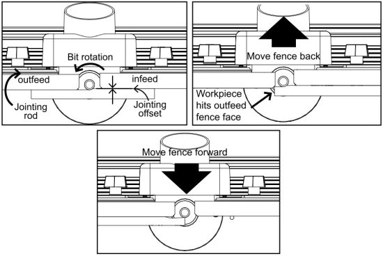
The independently adjustable fence faces allow you to use your router table as a vertical jointer. To set up for jointing, remove the two jointing rods (38) stored in the fence extrusion. Loosen the knobs securing the outfeed fence face. There are two sets of round channels in the fence extrusion behind the fence faces, that allow you to offset the outfeed fence face 1⁄16″ or 1⁄32″ from the infeed fence face. For a 1⁄16″ offset, slide the rods into the shallower recesses. For a 1⁄32″ offset, slide the rods into the deeper recesses. (When jointing, usually it is best to make light passes, so you’ll probably use the 1⁄32″ offset more frequently than the 1⁄16″ offset.) With the rods in place, tighten the outfeed fence-face knobs.

Install a straight bit in the router. Placing a steel rule or a piece of wood with a straight edge against the outfeed fence face, position the fence so the bit just grazes the rule or the piece of wood. Any straight bit can be used for jointing, but a flush-trim bit is the easiest to set up. Because the bit guide bearing is the same diameter as the cutter, you can align the outfeed fence face with the bearing. An up-cut spiral bit produces an almost chatter-free surface, but is a little more difficult to align with the fence face.
Use a scrap piece of wood to test the setup. If, as you feed the scrap past the bit, it runs into the leading end of the outfeed fence face, the fence is too far forward and you’re not removing enough material. Move the fence back a little. If you get snipe at the trailing edge of the scrap, the fence is too far back, and you’re removing too much material. Move the fence forward.
Using Your Router Table
Starting Pin
To use the starting pin, begin with your workpiece touching the pin, but not in contact with the router bit. Slowly pivot the workpiece into the bit until the workpiece makes contact with the bit guide bearing. Always feed the workpiece so the router bit rotates against (not with) the feed direction. With the workpiece in solid contact with the guide bearing, ease the workpiece off of the starting pin and feed the workpiece against the guide bearing.
![]() WARNING Use the starting pin when routing along curved edges and only with router bits that have a guide bearing. When routing along straight edges, always use the fence.
WARNING Use the starting pin when routing along curved edges and only with router bits that have a guide bearing. When routing along straight edges, always use the fence.
T-Slots
The fence extrusion features two T-slots, one on the top and one on the front face. Use T-bolts to attach feather boards and stops.
Center-Reading Tape Rule
Center the fence on the router bit and use the tape rule to position stops for routing stopped cuts.
![]()
Documents / Resources
 |
Kreg PRS2100 Precision Benchtop Router Table [pdf] Owner's Manual PRS2100, PRS2100 Precision Benchtop Router Table, Precision Benchtop Router Table, Benchtop Router Table, Router Table |