isolution DCT85 WIFI Module
Product Specification
- Type: RK3588.3_004
- Date: 2022-10-21
- Version: 1.3
- Approver: LUMQ
Detailed Product Information
Summary
The RK3588.3_004 is a new generation Android-12 system board featuring the RK3588 Chip, offering high integration and performance for smart display solutions. It is suitable for applications like educational electronic whiteboards, meetings, and public information displays.
Key Features
- Windows NFC OPSHDMII/OUSB3.0
- 8 lane VByOne3840*2160*10bit/60HZ
- 1000M OPS 1000M; WIFI 5M.2 E key WIFI 6
- Multiple connectivity options including HDMI, TYPE C USB3.0, USB2.0, HDMI in, DP in, TYPE C in, and Micro-card HDMI1+ HDMI2 or HDMI3 or DP or type-c +USB+
- Supports infrared touch screen for writing function and shortcut functions
- Automatic switching between different systems (e.g., Windows to Windows, Windows to Android)
- Ambient light sensor and temperature sensor for special features like real-time monitoring of internal temperature and brightness adjustment based on ambient light intensity
- Capability to display multiple input sources simultaneously on the same screen
Product Usage Instructions
Installation
Follow the provided installation guide to securely mount the RK3588.3_004 board in your desired location.
Connectivity
Connect the necessary cables and peripherals to the designated ports on the board according to your setup requirements.
Power On
Power on the RK3588.3_004 board and follow the on-screen instructions for initial setup.
Specifications
- Chip: RK3588
- Operating System: Android-12
- Resolution: 3840 x 2160 at 10bit/60Hz
- Connectivity: HDMI, USB 3.0, USB 2.0, TYPE C, Micro-card HDMI
- Wireless: WIFI 5M.2 E key WIFI 6
FAQs
- Q: How do I switch between different input sources?
- A: You can switch between different input sources by accessing the input settings menu on the display.
- Q: Can I use this board with Windows operating system?
- A: Yes, the RK3588.3_004 board supports Windows operating system for versatile usage.
: QT-RD-014 :1 / 34
ist
:
:1.2
Product specification
RK3588.3_004
(Type) : (Date) : (Ver.) : (Approver):
RK3588.3_004 2022-10-21 Ver 1.3 LUMQ
Customer confirm
Customer Auditing
Customer Approval
signature:
signature:
signature:
date:
date:
date:
: QT-RD-014 :2 / 34
ist
:
:1.2
Change History
REV. (DATE) (PAGE)
V1. 3
20221021
ALL
(CONTENT)
(AUTHOR)
LUMQ
: QT-RD-014 :3 / 34
ist
:
:1.2
1. (Summary)
RK3588.3_004-12,RockchipRK3588
windows
NFC OPSHDMII
/OUSB3.0; 8 lane VByOne3840*2160*10bit/60HZ ; 1000M OPS 1000M; WIFI 5M.2 E key WIFI 6 1HDMI 1TYPE C USB3.0,USB2.0,HDMI in,DP in,TYPE C in,Micro-card HDMI1+ HDMI2 or HDMI3 or DP or type-c +USB+
RK3588.3_004 is a new generation of Android-12 system board. RK3588 Chip on board which is a
highly integrated and high performance smart display solution. The board has some characteristic
function suitable for educational electronic whiteboard , meeting and Public information display. Provide multiple touch screen connectionBecause of mainboard combined with infrared touch
screen, the writing function and other shortcut function is realized on the android and touch automatic switching between different systems. (e.g. Windows to windows, windows to android)
Support ambient light sensor and temperature sensor, so they bring some special features: Temperature sensor can real-time monitoring of internal temperature for your equipment, and ambient light sensor can change backlight brightness based on the intensity of ambient light.
Provide common interface linked OPS: HDMI in; 3 I/0 ports; USB 3.0. Provide 8 lane VByOne interface, so it drives TFT_LCD panel resolution up to 3840*2160/60Hz . 1000M Ethernet on board. It also offers 1000M Ethernet for OPS; Wifi5 module is on board WIFI6 is M.2 E key connector; Provide a HDMI out and a TYPE C out , They can be same as mainboard display and be different; Provide various audio and video input terminals: e.g. USB3.0, USB2.0, HDMI in, TYPE C in,DP in,micro-card; USB slot can be used for updating software and playing multimedia. USB3.0 is public USB which can follow source skipping.
Multiple input sources are dynamically displayed on the same screen at the same time;
: QT-RD-014 :4 / 34
ist
:
:1.2
2. (Key Feature)
Item
Chip
CPU
GPU
NPU
System parameter
RAM
Flash
Android
version
type
resolution
panel
voltage
interface
Multimedia
video
HDMI in+DP in+TYPE C in
HDMI2.1 out+TYPE C out(DP1.2)
Socket
resolution
resolution
HDMI in&out DP1.2 in
PUBLIC USB3.0 MIC IN
ANDROID USB3.0 Ethernet(1Gb) Earphone out PUBLIC USB2.0 RS232 SPDIF out
Content
RK3588 Quad-core Cortex-A76+Quad-core Cortex-A55 ARM Mali-G610 MC4 computing power is up to 6TOPs 4+48G Bytes LPDDR4X-3733Mbps 128 GBytes-EMMC5.1 flash on board
12.0.0
TFT-LCD 3840*2160_60Hz 12V VByOne8 lanes—note1
decodeMPEG-1, MPEG-2, MPEG-4, H.263, H.264, H.265, VC-1, VP9, VP8, MVC, AV1
— H.265,VP9 8K/60Hz encodeH.265,H.264
HDMI1 in: MAX: 3840*2160@30Hz MAX: 3840*2160@60Hz
TYPE C out(DP1.2)–>MAX: 3840*2160@60Hz HDMI2.1 out–>MAX: 7680*4320@60Hz —note2
X3 HDMI in , x1 HDMI out A (HDMI type A) X1 DP in DP socket X2 USB3.0 A /(USB3.0 blue type A)—note3 X1 3.5mm (3.5mm standard earphone X1 USB3.0 A /(USB3.0 white type A) X2 RJ45 (RJ45 standard socket) x1 3.5mm (3.5mm standard earphone socket) x1 USB2.0 A (USB2.0 white type A) x1 DB9 (DB9 standard socket) x1 (Optical fiber socket)
: QT-RD-014 :5 / 34
ist
:
:1.2
power
OSD OSD language
USB3.0(TOUCH)
X1 B / (USB3.0 black type B)
Micro-SD card
x1 (standard micro-card socket)
TYPE C IN/OUT
x1 C (standard Type c socket
12V/4ARecommend 4A)(1.5A) +Panel TCON(2.5A) /
MB(1.5A) and panel Tcon demand=2.5A ;
5V_IN/3ARecommend 3A)
Main-board
5V_STB/1A(Recommend 1A);
Power demand
18V/1.2A(Recommend 1.2A) : USB 3.5A/5V;
(18V~24V) 2.1 (:10W*2+15W)
TYPE C (18V~24V): (MAX:20V/5A)
, (normal, standby,STR)
Working mode
Standby <0.15 W ()(standby power<0.15W,board only)
, .(English, Simplified Chinese and so on)–
Earphone out
16/32
S/PDIF out
IEC 60958 TYPE 2 (Optical);
/ Audio out/in
Characteristic function and Expandable
interface
PDM in
6*MICs PDM
AMP power/ Freq. response
Sensor and modules
OPS /OPS interface
/FrontIO borad
//
(L+R )2*10W(8/0.5Vrms)+(Bass)15W((4/0.5Vrms) / distortion<1%/18V );
150Hz~15KHz@+/-2dB(0.5Vrms/1K_Sine, with EQ disable)
NFC//PM2.5 PDM ; MIC USB2.0+
Temperature-sensor on board; Light Sensor module support ; NFC/Fingerprint/PM2.5 module support ;PDM;MIC module support; –note 4 41P FFC cable connector : 1. USB3.0 out(public USB+LAN USB) *1+USB2.0 out*2; 2. HDMI2.0 in*!; 3. UART(3.3V)*1; 4. GPIOs*4(Detect , the state, switch on, OPS power on/off); 51P FFC cable connector : 1. Public USB3.0 in*1; 2. USB3.0 out (Touch USB+public USB)*1 ; 3. HDMI2.0 in*1; 4. GPIOs*55. TYPE C network, TYPE C —note 4 1. IR remote*1 ; 2. KEY ADC Pin*2; 3. LED-IO*2(PWM-IO*1)4. 2
: QT-RD-014 :6 / 34
ist
:
:1.2
IR/KEY/indicator PM-GPIO; 5. I2C bus *1; 6. OPS ( OPS
LED
)
/WIFI
SDIO-WIFI5 PCIE-WIFI5/6 ; 5.0 WIFI FAE
/camera
USB3.0 // GPIO
1. Double touch data channe :
/touch
USB2.0(android)+USB2.0(others) or UART(android)+USB2.0(others)
2. USB2.0 PC
NOTE1: VBYONE FFC 900
NOTE2: TYPE C out HDMI out 3840*2160@60Hz HDMI out 7680*4320
TYPE C out ( USB )
NOTE3: Public USB3.0/2.0
NOTE4:
NOTE5OPS FFC
ist
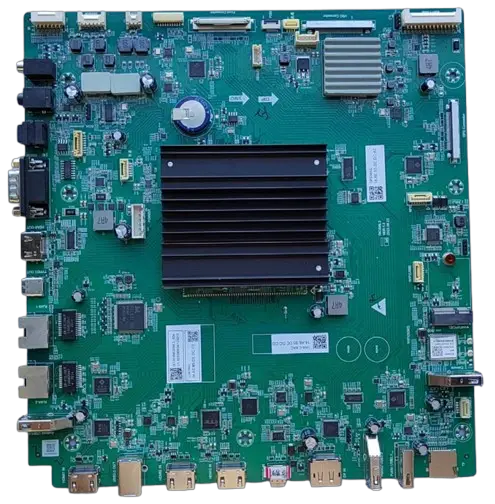
3.PCBA (PCBA PHOTO)
: QT-RD-014 :
:7 / 34 :1.2
ist
4.(TERMINAL POSITION )
: QT-RD-014 :
:8 / 34 :1.2
1 2 3 4
5
6 7
19 8
9
10
11
12
13
14
15
16 17 18
TERMINAL
MIC IN S/PDIF OUT
HDMI out RS232 (RS232 UART)
NO.
1 3 5 4
: QT-RD-014 :9 / 34
ist
:
:1.2
RJ45 IN–1000M LINE OUT TYPE C out
Android USB3.0 HDMI1 IN
USB3.0 OUT( face to host) HDMI2,3 in TYPE C in DP in
Public USB3.0( face to device) Public USB2.0( face to device)
Micro-SD card
78 2 6 9 10 11
12,13 14 15
16,19 17 18
1. MIC IN 2. 10 HDMI1 IN HDMI1.4B 2 HDMI IN HDMI2.0; HDMI1 IN
; HDMI1 (HDMI OUT TYPE C OUT); HDMI IN CEC 3. TYPE C IN DP IN+USB3.0 HOST+USB2.0 DEVICE+PD3.0 ( 20V*5A) 4. TYPE C OUT DP OUT+USB3.0 HOST +( 5V/1A) 5. TYPE C OUT HDMI OUT 6. RTC RTC >=12 7.
ist
5.(Connector position)
1
2
3
4
5
: QT-RD-014 :
:10 / 34 :1.2
6 7
8
9
14 15
16
13 10
17 18
11
12
ist
NO.
1 2 3 4 5 6 7
8
9 10 11 12 13 14 15 16 17 18
: QT-RD-014 :
:11 / 34 :1.2
CONNECTOR
CON3 CN7 CN8 CN9 P1 CN14 NJ1
CN4
CON2 P2 UN1
CN10 CN5 NJ5 NJ4 CN12 CN13 NJ9
FUNCTION (IR+KEY+LED connector) L+R L+R loudspeaker connector BASS loudspeaker connector (infrared touch connector) Front-io board connector PDM PDM connector light sensor connector VByOne (AUO/LG/INNOLUX TFL_LCD panel VbyOne connector) (board power in connector) OPS USB3.0/HDMI/IO (To ops:USB3.0,HDMI,I/O) PCIE-WIFI PCIE-WIFI connector–M.2_E-KEY PUB-USB2.0 connector TCON (panel TCON board power supply connector ) MIC Ext-MIC module connector TYPE-C (TYPE-C supply connector) NFC NFC connector Android USB2.0
1UN1 PCIE2.1 M.2 A KEY/E KEY WIFI5/6 2
: QT-RD-014 :12 / 34
ist
:
:1.2
6. (CONNECTOR DEFINITION)
: GPIO 3.3V
§NJ1 ( 4PIN/1.25MM) (Light sensor connector)
pin NO.
1 2
function
3.3V_out (<50mA) GND
pin NO.
3 4
function
SDA–(I2C ) SCL–(I2C )
§CN13 (7PIN/1.25MM) NFC/ (NFC CONNECTOR)
pin NO. function
pin NO. function
1
GND
5
CTL (3.3V/out,)
2
RX–()
6
GND
3
TX–()
7
3.3V_out (-150mA)
4
WAKE/IRQ(IN/3.3V,)
UART 3.3V_OUT CTL CTL
: QT-RD-014 :13 / 34
ist
:
:1.2
§CN12 ( 6PIN/2.54MM) TYPE-C (TYPEC power supply CONNECTOR)
pin NO. function
pin NO. function
1
GND
4
VCC_IN
2
GND
5
VCC_IN
3
GND
6
VCC_IN
TYPE- C 12V~24V, 65W 18V
§CN9 (10P/1.25MM) ( TOUCH IN connector)
Pin NO.
1 2 3 4 5
function
TX RX GND AD_D+ AD_D-
Pin NO.
6 7 8 9 10
function
GND PC_D+ PC_DGND 5V_out (<1A)
§P2 (41PIN/0.5MM) OPS HDMI,USB,IO (TO OPS: HDMI,USB,I/O ,UART CONNECTOR)
pin NO.
1 2
function
GND OPS-HPD
pin NO.
function
22
GND
23
OPS-PW-EN(GPIO)
ist
3 4 5 6 7 8 9 10 11 12 13 14 15 16 17 18 19 20 21
OPS-H-5V GND OPS-H-SDA OPS-H-SCL GND CEC OPS-RST GND OPS-HD-CLKN OPS-HD-CLKP GND OPS-HD-D0N OPS-HD-D0P GND OPS-HD-D1N OPS-HD-D1P GND OPS-HD-D2N OPS-HD-D2P
: QT-RD-014 :
:14 / 34 :1.2
24
OPS-ON(GPIO)
25
OPS-OK(GPIO)
26
OPS-DET(GPIO)
27
OPS-U-RX
28
OPS-U-TX
29
NC.
30
TP-OPS-D+
31
TP-OPS-D-
32
GND
33
OPS-D+
34
OPS-D-
35
GND
36
OPS-SS-RX-
37
OPS-SS-RX+
38
GND
39
OPS-SS-TX-
40
OPS-SS-TX+
41
GND
§CON2 ( 2*14PIN/2.0MM) (POWER AND BACKLIGHT CONTROL CONNECTOR)
No.
1
2 3 4 5
Function
No.
STB (on/off) ( 15
)
BL-ON/OFF
16
BL_PWM )
17
BL_ADJ )
18
5V_IN 5V
19
Function
12V_IN 12V
GND( ) AMP VCC-note GND( ) AMP VCC-note
: QT-RD-014 :15 / 34
ist
:
:1.2
5V_STB_IN 5V
6
20
GND( )
7
5V_IN 5V
21
18V_IN 18V
8
NC
2 2
GND( )
9
12V_IN 12V
23
18V_IN 18V
10
GND( )
2 4
GND( )
11
12V_IN 12V
25
18V_IN 18V
12
GND( )
2 6
GND( )
13
12V_IN 12V
27
18V_IN 18V
14
GND( )
28
GND( )
AMP_VCC 18V~24V; BL-ADJ BL-PWM IO
BL-ADJ BL-PWM
§CN5( 5PIN/2.0MM) (Panel TCON power connector)
pin NO.
1 2 3 4 5
function
GND GND LVDSVDD (12V out for TCON) — TCON LVDSVDD (12V out for TCON) — TCON LVDSVDD (12V out for TCON) — TCON
: QT-RD-014
ist
:
§P1 (51PIN/1.25MM) (Front board connector)
:16 / 34 :1.2
pin NO.
1 2 3 4 5 6 7 8 9 10 11 12 13 14 15 16 17 18 19 20 21 22 23 24 25 26
function
FRT-PUB-DFRT-PUB-D+ GND FRT-PUB-RXFRT-PUB-RX+ GND FRT-PUB-TXFRT-PUB-TX+ GND FRT-MIX-DFRT-MIX-D+ GND FRT-MIX-RXFRT-MIX-RX+ GND FRT-MIX-TXFRT-MIX-TX+ GND FHDMI_HPD FHDMI_5V FHDMI_SDA FHDMI_SCL CEC GND FHDMI_CLKN FHDMI_CLKP
pin NO.
27 28 29 30 31 32 33 34 35 36 37 38 39 40 41 42 43 44 45 46 47 48 49 50 51
function
GND FHDMI_D0N FHDMI_D0P GND FHDMI_D1N FHDMI_D1P GND FHDMI_D2N FHDMI_D2P GND TP_SEL FHUB_RST FHDMI_DET NET-USB-DNET-USB-D+ GND I2C_SDA I2C_SCL FUSB_EN 5V_PD FTYPE-C_DET GND OPS-RST SWITCH-CN 5V_PD
: QT-RD-014
ist
:
§CN13 (51PIN/0.25MM) (Panel TCON connector)
:17 / 34 :1.2
pin NO.
function
1
GND
2
VB1_7P
3
VB1_7N
4
GND
5
VB1_6P
6
VB1_6N
7
GND
8
VB1_5P
9
VB1_5N
10
GND
11
VB1_4P
12
VB1_4N
13
GND
14
VB1_3P
15
VB1_3N
16
GND
17
VB1_2P
18
VB1_2N
19
GND
20
VB1_1P
21
VB1_1N
22
GND
23
VB1_0P
24
VB1_0N
25
GND
26
VB1_LOCKN
45~51P CN5
pin NO.
27 28 29 30 31 32 33 34 35 36 37 38 39 40 41 42 43 44 45 46 47 48 49 50 51
function
VB1_HTPN GND NC NC OPTION1 NC I² C_SCL I²C_SDA VB1_FORMAT NC NC NC GND GND GND GND NC NC PVCC(12V) PVCC(12V) PVCC(12V) PVCC(12V) PVCC(12V) PVCC(12V) PVCC(12V)
: QT-RD-014
ist
:
§CN7( 6PIN/2.0MM) (Loudspeaker connector)
:18 / 34 :1.2
pin NO.
1 2 3
function
NC. R+ R-
pin NO.
4 5 6
function
NC L+ L-
§CN7( 3PIN/2.0MM) (BASS Loudspeaker connector)
pin NO.
1 2
function
NC BASS-
pin NO.
3
function
BASS+
§CON3 (2*7PIN/2.0MM) ++
pin NO.
1 2
function
IR-IN 3.3V-STB
pin NO.
8 9
function
OPS-RST KEY1-IN
: QT-RD-014 :19 / 34
ist
:
:1.2
3
SDA
10
KEY0-IN
4
LED-PWM
11
PM-IO1
5
SCL
12
GND
6
LED-R
13
PM-IO2
7
GND
14
GND
KEY1 1.8V; KEY0 3.3V,
§NJ5 (8PIN/1.25MM)
pin NO. function
pin NO. function
1
MIC_DN
5
5V(out,0.5A)
2
MIC_DP
6
GND
3
GND
7
MIC-U-RX
4
GND
8
MIC-U-TX
USB GPIO
§NJ4 (6PIN/1.25MM)
pin NO. function
pin NO. function
1
AEC_R-
4
GND
2
AEC_R+
5
AEC_L-
3
GND
6
AEC_L+
MIC 1/8
ist
§CN14 (10PIN/0.5MM)
: QT-RD-014 :
MIC-PDM
:20 / 34 :1.2
pin NO. function
pin NO. function
1
3.3V
6
NC
2
GND
7
GND
3
SDA0
8
SCLK
4
SDA1
9
GND
5
SDA2
10
NC
RK3588 MIC PDM 6*DMICs.
§CN10 (5PIN/1.25MM) PUB-USB2.0
pin NO.
1 2 3
function
5V_OUT(500mA) DATADATA+
pin NO.
4 5
function
GND GND
§NJ9 (6PIN/1.25MM) ANDROID-USB2.0
ist
pin NO.
1 2 3
function
5V_OUT(500mA) DATADATA+
: QT-RD-014 :
:21 / 34 :1.2
pin NO.
4 5 6
function
GND GND GPIO
FAE
: QT-RD-014 :22 / 34
ist
:
:1.2
7. PCBA (/FAE DXF )
PCBA Mechanical Dimensions(More details, please contact sales to ask for dxf file)
4 1.6mm PCB = 235mm+/-0.5 mm PCB = 250mm+/-0.5mm, 15mm, 2.5mm;
4 layers board: thick=1.6mm,long=250mm+/-0.5mm,wide=245mm+/-0.5mm,max height top15mm bottom2.5mm
: QT-RD-014
ist
:
HDMI HDMI TIMING
HDMI/DP PC TIMINGHDMI COMMON PC TIMING
Format
VGA SVGA
XGA
SXGA SXGA WUXGA
Resolution
640×480
800×600
1024×768 1152×864 1280×960 1280×1024 1360×768 1920×1080
H.Freq(KHz)
31.5 37.9 37.5 37.9 48.1 46.9 48.4 56.5 60 67.5
60
64 80 37.5 37.5
V.Freq(Hz)
60 72 75 60 72 75 60 70 75 75
60
60 75 60 60
:23 / 34 :1.2
Standard
VESA VESA
VESA VESA
HDMI/DP DTV TIMING (HDMI COMMON DTV TIMING)
Format
Resolution
480i
720×480
480p
720×480
576i
720×576
576p
720×576
720p
1280×720
1080i
1920×1080
1080p
1920×1080
V.Freq(Hz)
60 60 50 50 50 60 50 60 50 60
ist
HDMI IN/DP IN 4K TIMING
3840*2160
40*2160
40*2160 40*2160 40*2160 (PIXEL CLOCK)=300MHZ 4096*2160
3840*2160
3840*2160
3840*2160
3840*2160
3840*2160
(PIXEL CLOCK)=600MHZ
3840*2160 4096*2160 4096*2160
4096*2160
: QT-RD-014 :
:24 / 34 :1.2
29.97HZ/R444
HZ/R444 HZ/R444 .98HZ/R444 HZ/R444
24HZ/R444 50HZ/Y420 59HZ/Y420 60HZ/Y420 50HZ/R444 59HZ/R444 60HZ/R444 50HZ/R444 59HZ/R444 60HZ/R444
HDMI2.1 OUT TIMING
480p 720p 1080p
4K 8K
640×480 720×480 1280×720 1920×1080 3840×2160 7680X4320
60HZ 60HZ 60HZ/50HZ 60HZ/50HZ 60HZ/50HZ 60HZ/50HZ
1 HDMI( HDMI1 ) 600MHZ 2HDMI HDCP1.4/2.3;
: QT-RD-014 :25 / 34
ist
:
:1.2
3 4K2K TIMING HDMI ;
4 TIMING EIA/CEA-816-X
Note1: PIXEL CLOCK=600MHz(HDMI1 only300MHz) all HDMI port on board is HDMI2.0 full speed;
Note2: PIXEL CLOCK=600MHz signal support HDCP 2.2, but HDCP function need licenses;
Note3: When input image is 4K2K, please use hight speed cable(HDMI2.0);
Note4: All of the above mentioned TIMING are commonly used, if you need to know more, please refer to EIA/CEA-816 timing list.
: QT-RD-014
ist
:
9. (MULTI-MEDIA SUPPORT LIST)
(VIDEO DECODE)
:26 / 34 :1.2
: QT-RD-014 :27 / 34
ist
:
:1.2
: QT-RD-014 :28 / 34
ist
:
:1.2
ist
(AUDIO DECODE)
: QT-RD-014 :
:29 / 34 :1.2
: QT-RD-014 :30 / 34
ist
:
:1.2
ist
IMAGE DECODER
AGE CODEC PPORT IMAGE SIZE
AXIMUM DATA RATE ONTAINER
MARKS
: QT-RD-014 :
:31 / 34 :1.2
ile format 1.02 48 pixels to 65536x65536pixles 0x1080@200fps (yuv420) 560m pixels/second
jpeg ot support non-interleaved scan
software support SRGB jpeg
software support adobe RGB jpeg
ist
10. () IR,KEY and indicator light circuit(Reference)
: QT-RD-014 :
:32 / 34 :1.2
IR
R10
100R OIRI_IN
C32 220pF
/
VDD3.3V RC30
47K
LED-R# LED-R#
RU117
: H:
1K G
S
D
S
QP9 G
2N7002
D
RU114 47K RU116 2.2K
LED-R QP10
2N7002
+5V_STB
LED-PWM LED-PWM RU120
1K G
D
RU119
2.2K +5V_Normal
LED-PWM#
QP11
2N7002
S
KEY 1_IN
R1 C2
SW5
4
3
1
2
K6
0V
0R
R2
10nF
SW2
4
3
1
2
K5
0.3V
2K_1%
R3
SW3
4
3
1
2
K4
0.6V
3K_1%
R4
SW4
4
3
1
2
K3
0.9V
4.99K
KEY 0_IN
SW8
4
3
1
2
Power
R8
NC
C1
10nF
SW7
4
3
1
2
K2
1.2V
SW6
4
3
1
2
K3
1.5V
R7
10K_1% R6
30K_1%
R5
0R
1. IR 3.3V~5V IR 3.3V ;
2. 1mA
3. KEY0 3.3V,KEY0 POWER ; KEY1(1.8V)
IC warning
– English: This device contains licence-exempt transmitter(s)/receiver(s) that comply with Innovation,
Science and Economic Development Canada’s licence-exempt RSS(s). Operation is subject to the following two conditions: (1) This device may not cause interference. (2) This device must accept any interference, including interference that may cause undesired operation of the device.
– French: L’émetteur/récepteur exempt de licence contenu dans le présent appareil est conforme aux CNR
d’Innovation, Sciences et Développement économique Canada applicables aux appareils radio exempts de licence. L’exploitation est autorisée aux deux conditions suivantes : 1) L’appareil ne doit pas produire de brouillage; 2) L’appareil doit accepter tout brouillage radioélectrique subi, même si le brouillage est susceptible d’en compromettre le fonctionnement
ist
12. IC
: QT-RD-014 :
:34 / 34 :1.2
TBD
FCC STATEMENT
1. This device complies with Part 15 of the FCC Rules. Operation is subject to the following two conditions: (1) This device may not cause harmful interference, and (2) This device must accept any interference received, including interference that may cause undesired operation. 2. Changes or modifications not expressly approved by the party responsible for compliance could void the user’s authority to operate the equipment.
NOTE: This equipment has been tested and found to comply with the limits for a Class B digital device, pursuant to Part 15 of the FCC Rules. These limits are designed to provide reasonable protection against harmful interference in a residential installation. This equipment generates uses and can radiate radio frequency energy and, if not installed and used in accordance with the instructions, may cause harmful interference to radio communications. However, there is no guarantee that interference will not occur in a particular installation. If this equipment does cause harmful interference to radio or television reception, which can be determined by turning the equipment off and on, the user is encouraged to try to correct the interference by one or more of the following measures:
Reorient or relocate the receiving antenna. Increase the separation between the equipment and receiver. Connect the equipment into an outlet on a circuit different from that to which the receiver is connected. Consult the dealer or an experienced radio/TV technician for help.
Radiation Exposure Statement This equipment complies with FCC/IC radiation exposure limits set forth for an uncontrolled environment. This equipment should be installed and operated with minimum distance 20cm between the radiator & your body
: QT-RD-014 :33 / 34
ist
:
:1.2
11. (ATTENTION)
(1) 80%; : -10 ~ 60°C; : 0 ~ 45°C (2) PCBA ESD/EOS (3) BGA (4) (5) OPS OPS OPS (6) FAE
(1) humidity 80%; Storage temperature-10 ~ 60°Cworking temperature:0 ~ 45°C
(2) Direct contact with the PCBA need to pay attention to the protection of ESD/EOS;
(3) This product contains BGA components, so don’t bend the board when you assemble the work;
(4) Check the connection’s correct before power on;
(5) If this product is suitable for OPS computer, please load and unload OPS computer under power off;
(6) This article part of the understanding of the need for related engineering and technical personnel;What is the technical do not understand, please contact us in time.
FCC STATEMENT 1. This device complies with Part 15 of the FCC Rules. Operation is subject to the following two conditions: (1) This device may not cause harmful interference, and (2) This device must accept any interference received, including interference that may cause undesired operation. 2. Changes or modifications not expressly approved by the party responsible for compliance could void the user’s authority to operate the equipment.
NOTE: This equipment has been tested and found to comply with the limits for a Class B digital device, pursuant to Part 15 of the FCC Rules. These limits are designed to provide reasonable protection against harmful interference in a residential installation. This equipment generates uses and can radiate radio frequency energy and, if not installed and used in accordance with the instructions, may cause harmful interference to radio communications. However, there is no guarantee that interference will not occur in a particular installation. If this equipment does cause harmful interference to radio or television reception, which can be determined by turning the equipment off and on, the user is encouraged to try to correct the interference by one or more of the following measures:
Reorient or relocate the receiving antenna. Increase the separation between the equipment and receiver. Connect the equipment into an outlet on a circuit different from that to which the receiver is connected. Consult the dealer or an experienced radio/TV technician for help.
Radiation Exposure Statement This equipment complies with FCC/IC radiation exposure limits set forth for an uncontrolled environment. This equipment should be installed and operated with minimum distance 20cm between the radiator & your body
IC warning
– English: This device contains licence-exempt transmitter(s)/receiver(s) that comply with Innovation,
Science and Economic Development Canada’s licence-exempt RSS(s). Operation is subject to the following two conditions: (1) This device may not cause interference. (2) This device must accept any interference, including interference that may cause undesired operation of the device.
– French: L’émetteur/récepteur exempt de licence contenu dans le présent appareil est conforme aux CNR
d’Innovation, Sciences et Développement économique Canada applicables aux appareils radio exempts de licence. L’exploitation est autorisée aux deux conditions suivantes : 1) L’appareil ne doit pas produire de brouillage; 2) L’appareil doit accepter tout brouillage radioélectrique subi, même si le brouillage est susceptible d’en compromettre le fonctionnement
Documents / Resources
 |
isolution DCT85 WIFI Module [pdf] User Guide DCT85 WIFI Module, DCT85, WIFI Module, Module |


