Quick Start Guide for tM-P4C4

Congratulations!
Congratulations on purchasing the tM-P4C4 – the most popular automation solution for remote monitoring and control applications. This Quick Start Guide will provide the information needed to get started with the tM-P4C4. Please also consult the User Manual for detailed information on the setup and use of the tM-P4C4.
What’s in the shipping box?
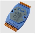
In addition to this guide, the shipping box includes the following items: tM-P4C4
Technical Support
- ICP DAS Website
http://www.icpdas.com/
Understanding the Hardware Specifications and Wiring Diagrams
Before installing the hardware, you should have a basic understanding of hardware specifications and the wiring diagrams.
System Specifications :
System Specifications :

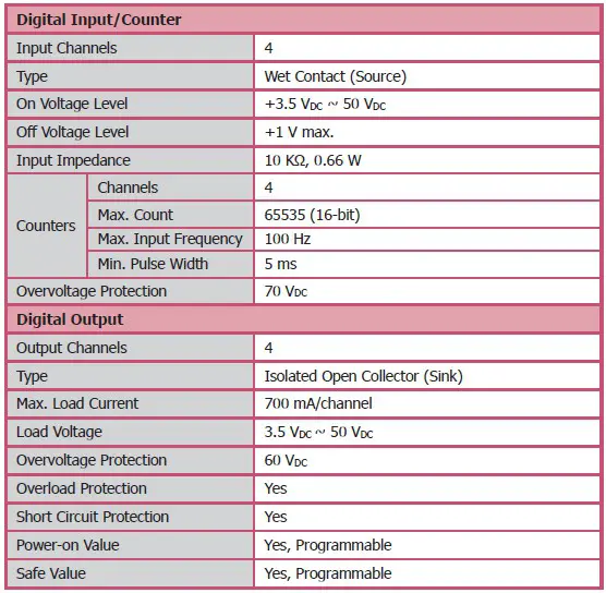
I/O Specifications:
Wire Connection:

Pin Assignment

Booting the tM-P4C4 in Init Mode
Make sure the switch is placed in the “Init” position.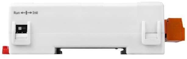
Connecting to the PC and the Power Supply
The tM-Series series is equipped with an RS-485 port for connection to a 232/USB converter to PC
Installing the DCON Utility
The DCON Utility is an easy-to-use tool designed to enable the simple configuration of I/O modules that use the DCON protocol.
Step 1: Locate the DCON Utility

The DCON Utility can be obtained from the companion CD or from the ICPDAS FTP site:
CD:\Napdos\8000\NAPDOS\Driver\DCON_Utility\setup\ http://ftp.icpdas.com/pub/cd/8000cd/napdos/driver/dcon_utility/
Step 2: Follow the prompts to complete the installation
After the installation has been completed, there will be a new shortcut to the DCON Utility on the desktop.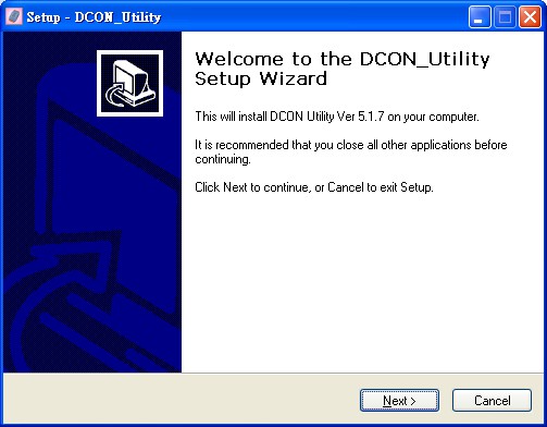
Using the DCON Utility to Initialize the tM-Series Module
The tM-Series is an I/O module based on the DCON protocol, meaning that you can use the DCON Utility to easily initialize it.
Step 1: Run the DCON Utility
Double-click the DCON Utility shortcut on your desktop.
Step 2: Use the COM1 port to communicate with the tM-Series
Click the “COM Port” option from the menu and a dialog box will be displayed that will allow you to set the communication parameters as described in the table below.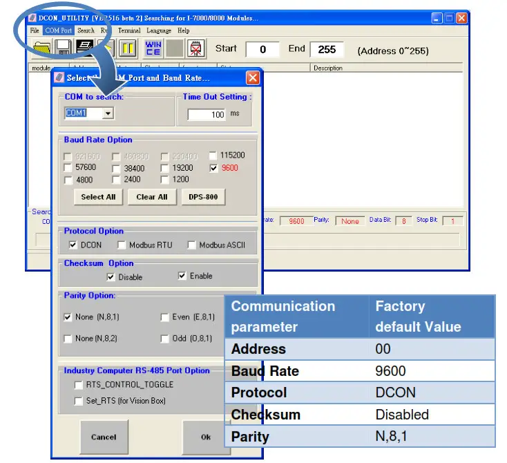
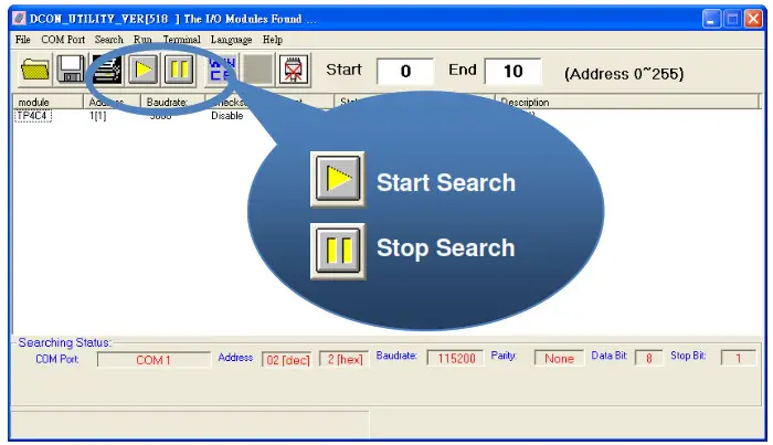
Step 3: Search for the tM-Series module
Click the “Start Search” button from the toolbox to search for the tM-Series module.
After the tM-Series module is displayed in the list, click the “Stop Search” button.
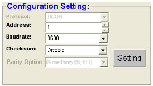
Step 4: Connect to the tM-Series
After clicking on the name of the module in the list, a dialog box will be displayed.
Step 5: Initialize the tM-Series module
Set the “Address” field in the dialog box to 1 and then click the “Setting” button to save the settings.
Rebooting the tM-Series Module in Normal Mode
Make sure the INIT switch is placed in the “Normal” position.
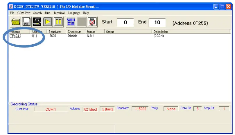
Starting the Module Operation
After rebooting the tM-Series module, search for the module to make sure the settings have been changed. You can double-click on the name of the module in the list to open the configuration dialog box.
Modbus Address Mapping
| Address | Description | Attribute |
| 30001 – 30004 | The counter value of digital input | R |
| 40481 | Firmware version (low word) | R |
| 40482 | Firmware version (high word) | R |
| 40483 | Module name (low word) | R |
| 40484 | Module name (high word) | R |
| 40485 | Module address, valid range: 1 – 247 | FWV |
| 40486 | Bits 5:0 Baud rate, valid range: 3 – 10 Bits 7:6 00: no parity, 1 stop bit 01: no parity, 2 stop bit 10:even parity. 1 stop bit 11:odd parity. 1 stop bit |
FtNV |
| 40488 | Modbus response delay time in ms. valid range: 0 – 30 | FINN |
| 40489 | Host watchdog timeout value. 0 – 255. in 0.1s | FLAN |
| 40492 | Host watchdog timeout count, write 0 to clear | RAN |
| 10033 – 10036 | Digital input value of channel 0 – 3 | R |
| 10065 – 10068 | High latched values of DI | R |
| 10073 – 10076 | High latched values of DO | R |
| 10097 – 10100 | Low latched values of DI | R |
| 10105 – 10108 | Low latched values of DO | R |
| 00001 – 00004 | The digital output value of channel 0 ∼3 | FLAN |
| 00129 – 00132 | Safe value of digital output channel 0 ∼ 3 | RAN |
| 00161 – 00164 | Power on the value of digital output channel 0 ∼3 | FINV |
| 00193 – 00196 | Counter update trigger edge of channel 0 ∼3 | FtNV |
| 00513 – 00518 | Write 1 to clear counter value of channel 0 ∼ 3 | W |
| 257 | Protocol selection. 0: DCON. 1: Modbus | RNV |
| 258 | 1: Modbus ASCII. 0: Modbus RTU | RAN |
| 260 | Modbus host watchdog mode 0: same as 1-7000 1: can use AO and DO command to clear host watchdog timeout status |
| Address | Description | Attribute |
| 261 | 1: enable, 0: disable host watchdog | RAN |
| 264 | Write 1 to clear latched DIO | W |
| 265 | DI active state, 0: normal, 1: inverse | R/W |
| 266 | DO active state, 0: normal, 1:inverse | R/W |
| 270 | Host watchdog timeout status, write 1 to clear host watchdog timeout status | RAN |
| 273 | Reset status, 1: first read after powered on, 0: not the first read after powering on | R |
Note: For tM DIO modules, Modbus registers to start at 00033 or 10033 can be used to read the digital input values. For M-7000 DIO modules, they are 00033 or 10001.
Copyright © 2009 ICP DAS Co., Ltd. All Rights Reserved.
E-mail: service@icpdas.com
Documents / Resources
 |
ICP DAS tM-P4C4 4-Channel Isolated DI and 4-Channel Isolated DO Module [pdf] User Guide tM-P4C4, 4-Channel Isolated DI and 4-Channel Isolated DO Module, tM-P4C4 4-Channel Isolated DI and 4-Channel Isolated DO Module |