HBA 14-924 4 Key Compact Controller
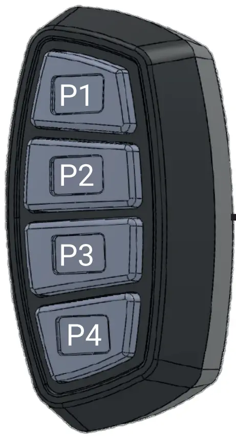
Specifications
- Product Code: ID-4
- Voltage: 10-30 VDC
- Output: 0.2Amp per wire
- IP Rating: IP65
- Dimensions: 38 X 75.8 X 23.8 mm
- Options:
- Adjustable Arm Mount
- Motorcycle Handle-Bar Clamp
Product Usage Instructions
Installation
Adjustable Arm Mount Installation:
- Attach and secure the controller onto the panel stand.
- Place the device onto a clean desired surface for easy accessibility.
- Use the supplied adhesive pad to secure the device onto the surface.
Note: The adhesive pad is for one-time use. Replace with other double-sided adhesive tapes if needed.
Clamp Mount Installation:
- Secure clamp mount part 3 onto the controller.
- Use the supplied screws to secure clamp mount parts 1 and 2 onto your desired mounting location.
- Adjust grip and size using the supplied rubber pad. Insert clamp mount part 3 into part 2, adjust the angle, and tighten.
Functions and Programming
Default Function: All buttons are default ON/OFF buttons.
Momentary Switch Programming Function:
- Press P1 and P4 for 5 seconds to enter setting procedure. Red LED backlight will flash 3 times.
- All buttons reset to default ON/OFF. Red LED lights steady on indicate buttons are in ON/OFF mode.
- Select button to enable/disable manual function; Red LED backlight indicates function selected.
- Press P1 and P4 for 5 seconds to exit setting mode. Red LED flashes once.
FAQ
Q: What is the warranty policy for the product?
A: The manufacturer offers a Limited Warranty of Thirty Six (36) months from the date of purchase. The warranty does not cover damage resulting from tampering, accident, abuse, misuse, negligence, unapproved modifications, fire or other hazard, improper installation or operation, or failure to maintain according to the manufacturer’s instructions.
Product Information
NOTE: Do not install and/or operate this product unless you have read and understand all the safety information and instructions contained in this manual.
IMPORTANT!
This manual provides all the necessary information for your product to be properly and safely installed. Please read all instructions before installation, and make sure you follow them carefully during the installation process. Failure to follow these instructions may result in DAMAGE to the product or vehicle, and/or SERIOUS INJURY to you and your passengers!
| Product Code | ID-4 |
| Voltage | 10-30 VDC |
| Output | 0.2Amp per wire |
| IP Rating | IP65 |
| Dimension | 38 X 75.8 X 23.8 mm |
| Options | – Adjustable Arm Mount
– Motorcycle Handle-Bar Clamp |
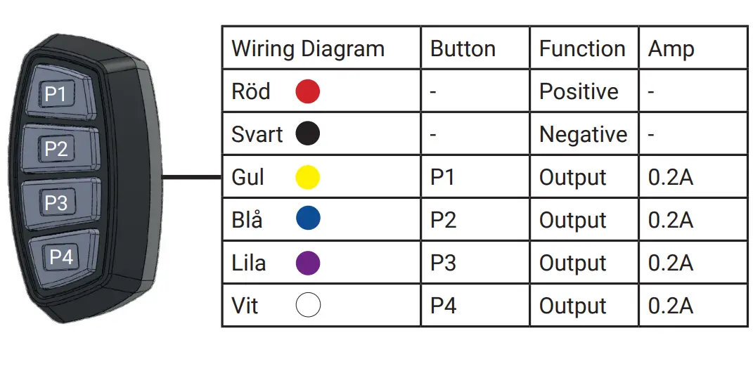
Wiring Diagram
FUNCTIONS AND PROGRAMMING
Default – All buttons are default as ON/OFF Button Momentary Switch Programming
Function To set function buttons as a momentary switch
- Press P1 and P4 for 5 seconds to enter the setting procedure. Red LED backlight will flash 3 times to indicate you have entered the setting mode.
- By entering the setting mode. All buttons will reset back to default as ON/OFF. (Red LED backlight on all buttons will turn into steady indicating the buttons are now in ON/OFF)
- Press the selected button to enable or disable the manual function. Red LED backlight on the button will indicate which function you have selected (indication shown as following)
- Press P1 and P4 for 5 seconds to exit the setting procedure. Red LED backlight will flash once to indicate you have exited the setting mode.
Adjustable Arm Mount
Installation:
Attach and secure the controller onto the panel stand. Place the device onto a clean desired surface, where it can be easily accessible to the user. Use the attached adhesive pad* to secure the device onto the surface. Should you wish to remove / re-locate the controller, you may use alcohol or similar cleaning formula to remove the left-over adhesive residue.
* The supplied adhesive pad is designed for one time use. You may replace it with other double side adhesive tapes.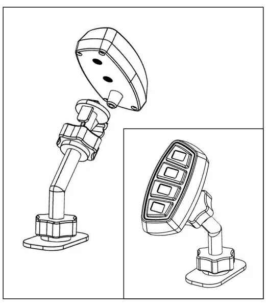
Adjustable Arm Mount
Installation:
- Secure clamp mount part 3 onto the controller.
- Use the supplied screws to secure clamp mount part 1 and 2 onto your desire mounting location. Use the supplied rubber pad to help adjusting the grip and size of the mount.
- Insert clamp mount part 3 into part 2. Adjust the angle and tighten the part.

Manufacturer Limited Warranty Policy: The manufacturer warrants that on the date of purchase this product. This Limited Warranty extends for Thirty-Six (36) months from the date of purchase. DAMAGE TO PARTS OR PRODUCTS RESULTING FROM TAMPERING, ACCIDENT, ABUSE, MISUSE, NEGLIGENCE, UNAPPROVED MODIFICATIONS, FIRE OR OTHER HAZARD; IMPROPER INSTALLATION OR OPERATION; OR NOT BEING MAINTAINED IN ACCORDANCE WITH THE MAINTENANCE PROCEDURES SET FORTH IN MANUFACTURER’S INSTALLATION AND OPERATING INSTRUCTIONS VOIDS THIS LIMITED WARRANTY.
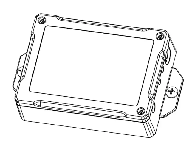
Installation
INSTALLATION MANUAL FS-6P RELAY BOX
NOTE: Do not install and/or operate this product unless you have read and understand all the safety information and instructions contained in this manual.
| Input Voltage | 12/24 V |
| Input @ 12V | 20A x 1 (i1) |
| Output @ 12V | 20A x1 (x1)
1A x1 (i2-i8) 5A x2 (x3-x4) 0,2A x1 (x5) Positiv/Negtiv x1 (x6-x7) Trigger at 0,2A x1 |
| Working Temperature | -300C to +650C |
| Dimension | 123,6 x 29,5 x 74,4 mm |
DIAGRAM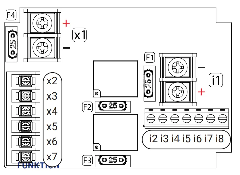
| I/O | Function | Linked | Amp (12V) | Fuse |
| i1 | Input | 20Amp | F1 | |
| i2 | Plus | 1Amp | ||
| i3 | Ground | – | ||
| i4 | Input | x3 | – | |
| i5 | Input | x4 | – | |
| i6 | Input | x5 | – | |
| i7 | Input | x6/x7 | – | |
| i8 | IGN | – | ||
| x1 | Output | 20Amp | F4 | |
| x2 | Ground | – | ||
| x3 | Output | 5Amp | F2 | |
| x4 | Output | 5Amp | F3 | |
| x5 | Output | 0,2Amp | ||
| TRI.+ | ”Common positive and negative” | 0,2Amp | ||
| TRI.- | – |
Function
| TRI.+/TRI.- | |
| Function | I/O TRI.+/TRI.- Provides the convenience of sending both positive and negative signals at the same time to its connected devices. |
| Setting | – Connect your desired input signal to I/O i7.
– I/O i7 will now activate TRI.+/TRI.- when enabled. |
Warning!
Proper placement and installation of this product are vital for it to operate at its optimum efficiency. It is your responsibility to determine a suitable mounting location for the product so as to ensure the safety of all passengers onboard. Do not install this product or route any wires within the airbag deployment area of your vehicle as it may damage or reduce the effectiveness of the airbag. In the worst-case scenario, it may even become a projectile that could cause serious injury or death. Before installation, please refer to the manual of your vehicle and avoid insalling it within the airbag deployment area. Manufacturer Limited Warranty Policy: The manufacturer warrants that on the date of purchase of this product. This Limited Warranty extends for Twelve (12) months from the date of purchase. DAMAGE TO PARTS OR PRODUCTS RESULTING FROM TAMPERING, ACCIDENT, ABUSE, MISUSE, NEGLIGENCE, UNAPPROVED MODIFICATIONS, FIRE OR OTHER HAZARD; IMPROPER INSTALLATION OR OPERATION; OR NOT BEING MAINTAINED UNDER THE MAINTENANCE PROCEDURES SET FORTH IN MANUFACTURER’S INSTALLATION AND OPERATING INSTRUCTIONS VOIDS THIS LIMITED WARRANTY.
Contact
- Tel. 08-880 900
- info@hba.nu
- www.hba.nu
Documents / Resources
 |
HBA 14-924 4 Key Compact Controller [pdf] Installation Guide 14-924 4 Key Compact Controller, 14-924, 4 Key Compact Controller, Key Compact Controller, Compact Controller, Controller |


