Generic GPS Speedometer with Tyer Pressure Multi Function Gauge
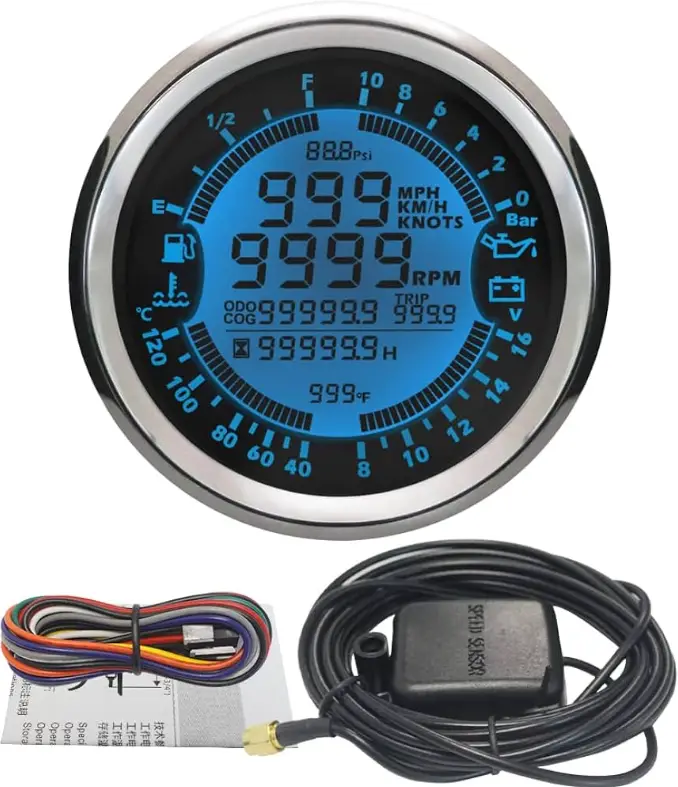
Usage Instructions

| Gauge Cable Harness Definition | |
| black | Power Ground – |
| red | Power+(12/24V) |
| blue | Left Turn (+) |
| pink | Hazard Alarm(+) |
| purple | Right Turn (+) |
| white | High Beam(+) |
| Brown | Oil Pressure Alarm(+) |
| green | Neutral(-) |
| green | Gear 1(-) |
| green | Gear 2(-) |
| green | Gear 3(-) |
| green | Gear 4(-) |
| green | Gear 5(-) |
| green | Gear 6(-) |
| yellow | Fuel Gauge signal(ohm) |
| orange | Engine Speed RPM signal(pulse) |
| yellow | TX |
|
white |
RX(Connect Tire Pressure sensor
Adapter TX) |
| grey | External Button (+) |
| orange | lgnition coil RPM signal |
| Tyer Pressure Adapter Cable Harness | |
| black | Power Ground – |
| red | Power 5~12V + |
| green | Signal |
Install the Gauge
- a. Place the motorcycle on a level and secure area. Disconnect the battery.
- b. Refer to the appropriate factory service manual and remove the OEM speedometer.
- c. Mount the new speedometer in the desired location.
- d. Locate and route the wires from the rear of the gauge to the existing OEM speedometer sensor wiring. You may extend or shorten the gauge wires as needed for your application.
- e. Securely fasten the GPS antenna, preferably outdoors (or inside front windscreen) so that it has a clear view of the sky to pick up satellite signals. Connect the antenna cable to socket on the gauge. Do not cut cable.
- f. After turning power on, allow the gauge to sample satellite signal for 1 minute.
- g. All data is for reference only and should not be trusted as sole navigation source.
Parameter Menu:ALAR, PULSE, oiL i,oiL dA, odo, Unit
Press and hold the back button, then power on. The LCD will keep switching & showing “ALAr, PULSE, oiL i , oiL dA , odo, Unit” Long press to switch. Choose the target menu, release button to enter setting.
- “ALAR”: change overspeed buzzer alarm threshold value

After selecting “ALAR”, the LCD will show for example “080” (buzzer will be on when speed over 80km/h), press the button to change the flashing digit from 10 to 240 to set target overspeed buzzer alarm threshold value. - “PULSE”: Set the engine speed RPM Ratio, unit: pulse/rpm, range: 0.5-655.3

How to confirm RPM Ratio?- a. If your sensor is installed on the flying wheel panel, the RPM ratio is equal to the number of gears of the engine.
- b. Normal RPM Ratio for Reference:
OutBoard Engine InterBoard or Gasoline Engine Diesel Engine Electric Poles RPM Ratio Cylinder Stroke RPM Ratio RPM Ratio=Gear Number 4 2 4 4 2 6 3 6 4 3 8 4 8 4 4 10 5 10 4 5 12 6 12 4 6
Wiring guide to get RPM Tach signal from RPM tach Sensor

Wiring guide to get RPM Tach signal from ignition coil directly

oiL i”(Set Fuel Gauge Signal)
LCD will show “2”(ohm range 10~180Ω). Press button to set target ohm range depends on table below Release button and wait for menu to complete flashing.
| LCD Menu | Ohm Signal Range |
| 0 | 0-190Ω |
| 1 | 0-180Ω |
| 2 | 10-180Ω |
| 3 | 240-33Ω |
| 4 | 240-30Ω |
“oiL dR” (no need setting)
odo”(Set Total Odometer)

After selecting “odo”, the LCD will show for example “5000” (5000 km) , press the button to change the flashing digit from 0 to 999999 to set the target odometer value.
“ Unit”(Set Unit: km/h, mph,NMI)

LCD will switch show km/h, mph, NMI .Then release button, and wait for menu to complete flashing.
“ Tire Pressure”


Wiring guide to connect Tyer Pressure Adapter to Gauge

Odometer & Trip Odometer
Power on the speedometer, and long Press to reset the Trip Odometer to Zero.
Please noted: After setting, you should disconnect both Power+ and GND, and then re-power on, then it will save the setting. If you just cut Power +, then it’ll not work properly.
Documents / Resources
 |
Generic GPS Speedometer with Tyer Pressure Multi Function Gauge [pdf] Instructions GPS Speedometer with Tyer Pressure Multi Function Gauge, GPS, Speedometer with Tyer Pressure Multi Function Gauge, Tyer Pressure Multi Function Gauge, Multi Function Gauge, Function Gauge, Gauge |