cVEND plug II Compact Payment Module
“
Specifications
- Product Name: cVEND plug II
- Product Type: Terminal for Contactless Payment and
Ticketing - Manufacturer: FEIG ELECTRONIC GmbH
- Release Date: 2024-12-09
Product Usage Instructions
1. Safety Instructions
Before using the cVEND plug II, read all safety instructions
provided in the user manual to ensure safe operation.
2. Scope of Delivery
Check the contents of the package to ensure all components are
included before proceeding with the installation.
3. Installation
Follow the mounting instructions provided in section 6.1 of the
manual to properly install the cVEND plug II.
4. Electrical Connections
Refer to section 7 for guidance on making electrical connections
to the cVEND plug II for proper functionality.
5. Cleaning and Care
Regularly clean the cVEND plug II as per the instructions in
section 10 to maintain its performance and prolong its
lifespan.
FAQ
Q: What should I do if the cVEND plug II is not functioning
correctly?
A: Check the electrical connections and cleanliness of the
device. If issues persist, refer to the troubleshooting section of
the manual or contact customer support.
Q: Can I use the cVEND plug II in outdoor environments?
A: The manual does not guarantee perfect function in cross
environments, so it is recommended to use the device in suitable
indoor environments.
“`
PAYMENT
=== Ende der Liste für T extm arke Deckbl att ===
Installation
cVEND plug II
Terminal for Contactless Payment and Ticketing
1
CVENDII – User Manual 2024-12-09
PAYMENT
cVEND plug II
Installation
© Copyright by
FEIG ELECTRONIC GmbH Industriestraße 1a D-35781 Weilburg Tel.: +49 6471 3109-0 https://www.feig.de/en/
Note
With the edition of this document, all previous editions become void. Indications made in this manual may be changed without previous notice.
The reproduction, distribution and utilization of this document as well as the communication of its contents to others without express authorization is prohibited. Offenders will be held liable for the payment of damages. All rights reserved in the event of the grant of a patent, utility model or design.
Composition of the information in this document has been done to the best of our knowledge. FEIG ELECTRONIC GmbH does not guarantee the correctness and completeness of the details given in this manual and may not be held liable for damages ensuing from incorrect or incomplete information. Since, despite all our efforts, errors may not be completely avoided, we are always grateful for your useful tips.
The instructions given in this manual are based on advantageous boundary conditions. FEIG ELECTRONIC GmbH does not give any guarantee promise for perfect function in cross environments and does not give any guaranty for the functionality of the complete system which incorporates the subject of this document.
FEIG ELECTRONIC call explicit attention that devices which are subject of this document are not designed with components and testing methods for a level of reliability suitable for use in or in connection with surgical implants or as critical components in any life support systems whose failure to perform can reasonably be expected to cause significant injury to a human. To avoid damage, injury, or death, the user or application designer must take reasonably prudent steps to protect against system failures. FEIG ELECTRONIC GmbH assumes no responsibility for the use of any information contained in this document and makes no representation that they free of patent infringement. FEIG ELECTRONIC GmbH does not convey any license under its patent rights nor the rights of others.
All brand names, trademarks or logos are property of their respective owners.
Page 2 of 33
PAYMENT
cVEND plug II
Installation
Contents
1 About this Manual
5
2 Safety Instructions
5
3 Product use
6
3.1 Product Versions………………………………………………………………………………………………… 6
4 Scope of delivery
7
5 Functional Elements
8
5.1 Front Side…………………………………………………………………………………………………………… 8 5.2 Back Side Standard Version ……………………………………………………………………………… 9 5.3 Back Side Flat Version ……………………………………………………………………………………. 10
6 Installation
11
6.1 Mounting ………………………………………………………………………………………………………….. 12
7 Electrical connections
13
7.1 X1 LAN-/Ethernet Interface ……………………………………………………………………………… 13 7.2 X2 USB OTG Interface …………………………………………………………………………………….. 14 7.3 X3 Serial Port RS232 V.24 (UART#1) ………………………………………………………………… 14 7.4 Connector X4 – RS232-LVTTL (UART#0) Interface ……………………………………………….. 15
7.4.1 Wake-Up ………………………………………………………………………………………………….. 16 7.5 X5 Power Supply Vcc ……………………………………………………………………………………… 17 7.6 Extension Interfaces………………………………………………………………………………………….. 18
7.6.1 Connector X11 – SAM and SDHC Interface …………………………………………………. 18 7.6.2 Connector X12 – Auxiliary Interfaces………………………………………………………….. 20 7.7 Connector X14 Serial Debug Port…………………………………………………………………….. 22
8 Signals
23
9 Security tamper
23 Page 3 of 33
PAYMENT
cVEND plug II
Installation
10 Cleaning and care
24
11 Technical Data
25
11.1 Dimensions ………………………………………………………………………………………………………. 27 11.1.1 Dimensions front side ………………………………………………………………………………. 27 11.1.2 cVEND plug II standard version internal dimensions ………………………………….. 28 11.1.3 cVEND plug II flat version internal dimensions …………………………………………… 29
12 Declaration of Conformity
30
12.1 Declaration of Conformity (CE) ………………………………………………………………………….. 30 12.2 Declaration of Conformity (UKCA) ……………………………………………………………………… 30 12.3 Radio Approval – USA (FCC) and Canada (IC) ……………………………………………………… 30
12.3.1 Integration Instructions FCC……………………………………………………………………… 31
13 Optional Extensions
33
Page 4 of 33
PAYMENT
cVEND plug II
Installation
=== Ende der Liste für T extm arke Note ===
1 About this Manual
These instructions describe the integration, assembly and connection of the cVEND plug II. The instructions are intended both for developers who want to integrate the payment terminal into the target system and for trained service staff who are tasked with operating and/or maintaining the cVEND plug II.
2 Safety Instructions
Safety Instructions
The device may only be used for the intended purpose designed for by the manufacturer. The operation manual should be conveniently kept available at all times for each user. Unauthorized changes and the use of spare parts and additional devices which have not been sold or
recommended by the manufacturer may cause fire, electric shocks or injuries. Such unauthorized measures shall exclude any liability by the manufacturer. The liability-prescriptions of the manufacturer in the issue valid at the time of purchase are valid for the device. The manufacturer shall not be held legally responsible for inaccuracies, errors, or omissions in the manual or automatically set parameters for a device or for an incorrect application of a device. Repairs may only be executed by the manufacturer. Installation, operation, and maintenance procedures should only be carried out by qualified personnel. Use of the device and its installation must be in accordance with national legal requirements and local electrical codes. · When working on devices the valid safety regulations must be observed. · Special advice for carriers of cardiac pacemakers: Although this device doesn’t exceed the valid limits for electromagnetic fields you should keep a minimum distance of 25 cm between the device and your cardiac pacemaker and not stay in an immediate proximity of the device respective the antenna for some time.
Pos : 13 /Steuermodul e/———— Seitenum bruc h ———— @ 0m od_1452083281983_0.docx @ 10032 @ @ 1
Page 5 of 33
PAYMENT
cVEND plug II
Installation
3 Product use
The cVEND plug II is an universal payment Terminal to accept debit and credit cards (Open-Loop) as well as Closed-Loop systems that can be operated independently. With optional expansion modules and housing components, the cVEND plug II can be adapted for different environments.
3.1 Product Versions
cVEND plug II is available in different versions which are shown in the following table:
Order-No.
6836.041.xx 6836.049.xx
Designation
cVEND plug II cVEND plug II flat
EMVCo L1 compliance
3.1a 3.1a
LAN connector
X1
X
–
Page 6 of 33
PAYMENT
cVEND plug II
Installation
4 Scope of delivery
All components and individual parts supplied with the respective article are described below.
1
Pos. 1
Description cVEND plug II
Quantity 1
Page 7 of 33
PAYMENT
cVEND plug II
5 Functional Elements
5.1 Front Side
3
4
Label 1 2 3 4
Description Contactless symbol
LED NFC antenna
Sealing
Installation
2 1
Page 8 of 33
PAYMENT
cVEND plug II
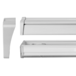
5.2 Back Side Standard Version
X14
X11
5
Installation
X12
X1
X2
X3
X4
X5
Label 5 X1 X2 X3 X4 X5
X11 X12 X14
Description Wrap around mounting edge LAN-/Ethernet Interface (10/100 Base-T)
USB OTG Interface Serial Interface RS232 V.24 (UART#1)
RS232-LVTTL (UART#0) Interface Voltage supply 5V DC
Connector for Piggyback Extension Boards Connector for Piggyback Extension Boards Serial Interface RS232-LVTTL (UART#2)
Page 9 of 33
PAYMENT
cVEND plug II
5.3 Back Side Flat Version
X14
X11
5
Installation
X12
X2
X3
X4
X5
Label 5
X2 X3 X4 X5 X11 X12 X14
Description Wrap around mounting edge
USB OTG Interface Serial Interface RS232 V.24 (UART#1)
RS232-LVTTL (UART#0) Interface Voltage supply 5V DC
Connector for Piggyback Extension Boards Connector for Piggyback Extension Boards Serial Interface RS232-LVTTL (UART#2)
Page 10 of 33
PAYMENT
cVEND plug II
Installation
6 Installation
The cVEND plug II can be installed flush in a non-conductive front plate. The front plate thickness must be 3 mm. A round opening with a diameter of 28.5 mm is required for installation. The cVEND plug II must be installed in the housing from the inside. If the LEDs of the cVEND plug II are to be used, additional light channels must be provided
28,5 mm
NOTICE To comply with EMVCo regulations:
· The contactless logo must be visible. · The upper edge of the cVEND plug II plastic dome and the target terminal front plate must be
on the same level. · Avoid any kind of conductive material in the vicinity of the cVEND plug II antenna. · Do not use conducting materials for fastening. The cVEND plug II front consists of a silicone rubber mat with integrated sealing lip and a fixed plastic dome made of polycarbonate, which shows the backlit contactless symbol. For mounting, the cVEND plug II front must be pressed firmly against the front of the housing. A clamping range of 2.5 mm is available for this purpose (see 5.2, fastening area (5), shown in green) on all sides of the cVEND plug II antenna board. For detailed dimension see 11.1 3D STEP Data are available on request.
Page 11 of 33
PAYMENT
cVEND plug II
Installation
6.1 Mounting
Prerequisite: A corresponding fastening unit must be available on the target system for fastening the cVEND plug II.
1. Remove protection foil from plug
28,5 mm
2. Push the cVEND plug II through the hole from the inside 3. Attach the cVEND plug II to the front of the machine.
Make sure that only the antenna of the cVEND plug II is used for mounting
cVEND plug II is mounted
Page 12 of 33
PAYMENT
cVEND plug II
Installation
7 Electrical connections
ATTENTION The device can be damaged by a short circuit. Only connect electrical connections when the device is de-energized.
Depending on the equipment, the device can be equipped with different interfaces to which various functions can be assigned.
7.1 X1 LAN-/Ethernet Interface
The LAN/Ethernet interface can be configured as an interface for host communication and/or as a cash register interface.
· 10/100 Base-T with standard RJ-45 connector. · Automatic “Crossover Detection” · TCP/IP protocol · IPv4
Recommended cable type: STP CAT5 (for operation at 10 Mbps or 100 Mbps).
Required connector type: RJ45
PIM-Assignment:
PIN
Label
1
TX+
2
TX
3
RX+
4
n.c.
5
n.c.
6
RX
7
n.c.
8
n.c.
Page 13 of 33
PAYMENT
cVEND plug II
Installation
7.2 X2 USB OTG Interface
The USB device interface can be used for communication depending on application and is usable as virtual COM-Port (CDC-ACM) and networking device (CDC-ECM).
NOTE · The USB interface is specified for max. 3 m (9,84 ft) cable length.
PIN-Assignment:
PIN
Label
1
DEV-Vcc
2
DEV-D-
3
DEV-D+
4
ID
5
GND
6
Shield
Direction I
I/O I/O
I –
Required connector type: Molex Micro Fit 43025-0600, 6-pole plug and the related crimp contact
ID (PIN 4)
· N.C: device operates as USB-Device · GND: Device operates as USB-Host
7.3 X3 Serial Port RS232 V.24 (UART#1)
The serial interface RS232 V.24 (UART#1) can be used by the application. The interface is an RS232 Interface on V.24 level. PIN-Assignment:
Pos
Label
1
Device RXD
2
Device TXD
3
Wake-UP
4
GND
Direction I O
I/O –
Required connector type: Molex Micro Fit 43025-0400, 4-pole and the appending related crimp-contact
Page 14 of 33
PAYMENT
cVEND plug II
Installation
7.4 Connector X4 – RS232-LVTTL (UART#0) Interface
At connector X4 a RS232 interface on LVTTL 3.3V level is provided. This interface offers also a hardware flow control.
PIN
Description
Direction
Comment
1
Device RTS
O
2
GND
–
3
Device RXD
I
4
Device TXD
O
5
Device CTS
I
6
Wake-Up
I/O
s. 0 Wake-Up
Required connector type: JST PHR-6 – housing, 6-pole, grid dimension 2.0 mm, Single Row and
JST SPH-002T-P0.5 or SPH-004T-P0.5 Crimp contact
NOTE:
The length of the cable to the RS232-LVTTL interface should be kept as short as possible, and must in any case not exceed 3 m.
Page 15 of 33
PAYMENT
cVEND plug II
Installation
7.4.1 Wake-Up
cVEND offers a standby mode which can be configured via software commands. If standby is activated the bidirectional Wake-Up I/O is used for signaling a wake-up event by the cVEND and can be used by the host to activate the cVEND.
Wake-Up by host: The host controller can awake the cVEND by pulling down the Wake-Up line.
NOTE:
If the standby – Wake-Up option is used in connection with the USB interface the USB connection will be interrupted while standby mode.
Page 16 of 33
PAYMENT
cVEND plug II
Installation
7.5 X5 Power Supply Vcc
ATTENTION For cVEND module integration the following recommendations must be followed:
· Device can be damaged by incorrect polarity or excessive voltage. · Observe correct polarity. · Use only a stable regulated supply voltage according to the voltage and ripple specifica-
tion given in the data sheet. · The device must be supplied by a limited power supply according EN 62368-1 PS1, only! · The cable length from the power supply should be as short as possible
Polarity of power supply:
PIN Label 1 Vcc 2 GND
Direction I –
Comment 5,0 V/DC
Required connector type: Molex Micro Fit 43025-0200, 2-pole and related crimp contact
cVEND plug II is specified for a supply voltage between 5,0 and 5,5 V. A supply voltage between 4.0 V and 2.5 V during the switch-on and switch-off phase is particularly critical for a possible malfunction of the device and should be passed through in < 10 ms. The voltage should be strictly monotonic and without overshoot and/or undershoot into the critical range.
The rise time at power on and the fall time at power off should be considered when the cVEND plug II is in full operation or in low-power sleep mode.
Recommended power on rise time
Recommended power off fall time
Page 17 of 33
PAYMENT
cVEND plug II
Installation
7.6 Extension Interfaces
Piggyback extension boards can be optionally plugged onto the X11 and X12 connectors.
How to attach the Piggyback Extension Boards and further details are described in the separate manual for the Extension Board.
Required connector type: Manufacturer ordering code 127GA-038GB-# 1.27MM x 1.27MM FEMALE HEADER SMT TYPE PROFILE= 4.40MM (BTB-02) Supplier: FJH die Steckverbinder GmbH
7.6.1 Connector X11 – SAM and SDHC Interface
Page 18 of 33
PAYMENT
cVEND plug II
Installation
PIN
Label
1
SDHC-DATA2
2
SDHC-CD
3
SDHC-DATA3
4
SDHC-PWR
5
SDHC-CMD
7
SDHC-CLK
9
SDHC-DATA0
11
SDHC-DATA1
12
SDHC-LED
13
SAM0-5V/3V
14
SAM0-1V8
15
SAM0-SEL-AB
16
SAM0-CMDVCC
17
SAM0-OFF
18
SAM0-OFF2
19
SAM0-RST
21
SAM0-CLK
23
SAM0-IO
25
SAM1-5V/3V
26
SAM1-1V8
27
SAM1-SEL-AB
28
SAM1-CMDVCC
29
SAM1-OFF
30
SAM1-OFF2
31
SAM1-RST
33
SAM1-CLK
35
SAM1-IO
37
3.3 V SW
38
5V-SW
6
8
10
20
22
GND
24
32
34
36
Direction I/O I I/O I/O O O I/O I/O O O O O O I I O O I/O O O O O I I O O I/O
O
O
Comment SDHC (LVTTL)
SAM0 Interface (LVTTL)
SAM1 Interface (LVTTL) Switched 3.3 V (off in standby) max.350 mA1
Switched 5 V (off in standby) max.350 mA GND
1 NOTICE The total current ox X11 PIN 37 (3.3 V SW) and X12 PIN 33 (3.3 V) must not exceed the limit
Page 19 of 33
PAYMENT
cVEND plug II
Installation
7.6.2 Connector X12 – Auxiliary Interfaces
The Auxiliary Interface at X12 offers digital I/O’s, I2C, SPI and USB Host interface and some other signals. Also the signals of UART#0 (Connector X4 – RS232-LVTTL (UART#0) ) are available at X12. Some of the GPIOs are already in use. Please contact cvend-support@feig.de before usage. Customized Firmware version might be required.
Page 20 of 33
PAYMENT
cVEND plug II
Installation
PIN
Label
1
GPIO1
2
GPIO2
3
GPIO3
4
GPIO4
5
GPIO5
6
GPIO6
7
GPIO6
8
GPIO7
9
SPI-CS
11
SPI-SCK
13
SPI-MISO
15
SPI-MOSI
17
I2C-SCL
19
I2C-SDA
21
RX
22
CTS
23
TX
24
RTS
25
USB VCC-EN (LVTTL)
26
USB-H-
27
USB-H+
28 USB-VCC-ERR (LVTTL)
29
SDHC-BV0
30
SDHC-BV1
31
SDHC-WP
32
WAKE-UP
33
3.3 V SW
34
RESET-IN
36
5 V
35 Vin-EXT
37
10 12 14
GND 16 18 38
Direction I/O I/O I/O I/O I/O I/O I/O I/O O O I O O I/O I I O O O I/O I/O I O O I
I/O
O
Comment
Digital I/O (LVTTL)
SPI Interface (LVTTL) I2C Interface (LVTTL) Alternative RS232 LVTTL UART#0 (see Connector X4 – RS232-LVTTL (UART#0) Interface)
USB Host Interface SDHC Interface Part 2 (LVTTL) (SDHC Interface Part 1 s. X11)
Wake-Up (s. 0 Wake-Up) Switched 3.3 V (off in standby) max.350 mA2
I
low active (LVTTL)
O
Permanent 5 V max. current depends on Vcc source at X5
I
Alternative power supply input to X5 (see X5 Power Supply Vcc)
–
GND
2 NOTICE The total current of X11 PIN 37 (3.3 V SW) and X12 PIN 33 (3.3 V) must not exceed the limit
Page 21 of 33
PAYMENT
cVEND plug II
Installation
7.7 Connector X14 Serial Debug Port
At connector X14 a serial interface (UART#2) on LVTTL 3.3V level is provided. On development devices this port is used as Linux Console. On secure productive devices this interface has no function.
PIN-Assignment:
PIN
Label
1
GND
2
Device RXD
3
Device TXD
Direction I O
Comment
Required connector type: Molex Micro Fit 43025-0400, 3-pole and the appending related crimp-contact; JST SPH-002T-P0.5 or SPH-004T-P0.5 Crimp contact
Page 22 of 33
PAYMENT
cVEND plug II
Installation
8 Signals
This chapter describes the signals generated by the cVEND operating system. Any further LED indications are described in the respective application-specific commissioning instructions.
1 x beep
Indicates that the cVEND is powered and has started the boot process. The boot routine takes about one minute.
The yellow LED flashes during the boot process.
1 x 1 x beep
The boot process is complete when all four green LEDs light up once and a signal tone sounds.
9 Security tamper
The terminal has an integrated battery-powered logic for detecting tampering attempts. If a tampering attempt is detected, the terminal deletes the entire sensitive key material and enters the ‘TAMPER DETECTED’ state. Reactivation is only possible by the manufacturer in a certified secure environment.
When the terminal is switched on, it reports the detected tampering attempt as follows:
beep … beep … beep
Tamper Event
· The red light lights up. · The buzzer emits beeps of 4 kHz every second.
· Manipulation message is sent cyclically on all serial interface with 115.200 baud, 8-N-1
· cVEND stops regular operation
NOTE
In addition, read the instructions in the “cVEND Security-Policy”, which can be found on the FEIG website in the download area.
ATTENTION
Security keys in the device are deleted. · Do not tamper with the device, e.g. by forcible damage. · Do not unscrew the device · Device must not be used or stored outside the specified ambient temperature · Do not remove or short circuit the integrated battery · Do not cause a short circuit on the device · Security keys can only be reactivated by FEIG Electronic
Page 23 of 33
PAYMENT
cVEND plug II
Installation
10 Cleaning and care
Always use soft cleaning cloths for cleaning and avoid using cleaning agents as far as possible. If cleaning agents are used, clean only with liquid soap.
Do not use any chemical, corrosive cleaning agents to avoid damaging the surface.
No maintenance is required for the cVEND plug II and its extensions.
Page 24 of 33
PAYMENT
cVEND plug II
Installation
11 Technical Data
Housing
Dimensions (W x H x D) Weight
· Module with front cover without housing (UL94 V-0)
· Front cover contactless symbol: Polycarbonate (Makrolon 6555), Plane: Silicon rubber
· Center frame: PA6 (UL94 V-0)
· Standard Version: 79 x 70 x 31,1 mm (visible 28,5 mm)
· Flat Version:
79 x 70 x 25,5 mm (visible 28,5 mm)
· 85 g
Temperature range Humidity Protection Class Pollution Degree
· Operating: -30 °C bis +70 °C ambient temperature · Storage: -30 °C bis +80 °C
· 5% bis 95 % non-condensing (moisture protective coating optional)
· Frontside: IP65 (if accurate installed)
· Inside:
IP00
· DIN EN IEC 62368-1: Grade 2
Shock and Vibration
· Class 5M3 according to IEC 60068-2-6 / IEC 60068-2-27
Vandalism Protection
· IEC 62262, IK10 (installed in equivalent robust housing)
Electrostatic discharge
· ISO 10605, Category 3
Power Supply
· 5,0 to 5,5 V DC (Ripple < 80 mVpp)
Power consumption operation Low power standby mode
RFID Interface
Supported Transponder Peripheral interfaces User interfaces CPU and security
· typ. < 1 A, peripherals excluded
· Power consumption < 1 mA (depending on hardware configuration and wake-up mode)
· Wake-up by digital input, time controlled and wakeup by card · Integrated Antenna · 13,56 MHz · Transmission power <= 1 W · ISO/IEC 14443-A / -B (NFC Read/Write module) in
EMVCo contactless mode · ISO/IEC 15693 · ISO/IEC 14443-4 compliant smart cards, NFC Type 1, 2 und 4 in
card-emulation mode, Mifare classic, Mifare ultralight and Sony Felica. Further technologies on request · ISO/IEC 15693 UID and mandatory commands · Ethernet – IEEE 802.3/Ethernet, 10/100 Mbps (optional) · RS232 (V.24) · RS232-LVTTL · USB 2.0 OTG incl. TCP/IP over USB support. · 6 LED (4 green, 1 red, 1 yellow), Buzzer, illuminated payment logo
· Secure 32 Bit ARM Cortex A7 CPU with up to 1 GHz clock Tamper protected and side channel attack resistant with real time memory encryption and true random number generator
· Real time clock battery backed (20 ppm accuracy)
Page 25 of 33
PAYMENT
Memory Battery MTBF at 55 °C (EN61709) Operating system
Payment Approvals
cVEND plug II
Installation
· 512 MByte RAM · 1 GByte FLASH · 3 V Lithium Battery, 540 mAh, Lifetime 15 years at 25 °C3
· 100.000 h
· cVEND.OS based on LINUX with cVEND Multi-Application architecture
· Fail-safe updates for operating system and application · Crypto Plug-Ins to protect sensitive data
· EMVCo Contactless Level 1 · PCI PTS 6.x, SRED incl. Open Protocol
3 The battery is used for the safety function and RTC. A higher ambient temperature leads to a shortened service life!
Page 26 of 33
PAYMENT
cVEND plug II
11.1 Dimensions 11.1.1 Dimensions front side
General tolerance +/- 10%
Installation
Page 27 of 33
PAYMENT
cVEND plug II
11.1.2 cVEND plug II standard version internal dimensions
Installation
PCB thickness tolerance +/- 10%
Page 28 of 33
PAYMENT
cVEND plug II
11.1.3 cVEND plug II flat version internal dimensions
Installation
Page 29 of 33
PAYMENT
cVEND plug II
Installation
12 Declaration of Conformity
12.1 Declaration of Conformity (CE)
Hereby FEIG ELECTRONIC GmbH declares that the radio equipment type cVEND plug II is in compliance with Directive 2014/53/EU. The full text of the EU declaration of conformity is available at the following internet address: https://www.feig.de/en/service/eu-declarations-of-conformity/
12.2 Declaration of Conformity (UKCA)
Hereby FEIG ELECTRONIC GmbH declares that the radio equipment type cVEND plug II is in compliance with Directive No. 1206 Radio Equipment Regulations 2017. The full text of the UKCA declaration of conformity is available at the following internet address: https://www.feig.de/en/service/ukca-declarations-of-conformity/
12.3 Radio Approval – USA (FCC) and Canada (IC)
Product name: cVEND plug II
FCC ID: IC:
PJMCVENDII 6633A-CVENDII
PMN: cVEND plug II HVIN: cVEND plug II
HMN:
Notice for USA and Canada
This device complies with Part 15 of the FCC Rules (§15.225) and with
RSS-210 of Industry Canada.
Operation is subject to the following two conditions.
(1) this device may not cause harmful interference, and
(2) this device must accept any interference received,
including interference that may cause undesired operation.
Unauthorized modifications may void the authority granted under Federal communications Commission Rules permitting the operation of this device.
This equipment has been tested and found to comply with the limits for a Class A digital device, pursuant to Part 15 of the FCC Rules. These limits are designed to provide reasonable protection against harmful interference when the equipment is operated in a commercial environment. This equipment generates, uses, and can radiate radio frequency energy and, if not installed and used in accordance with the instruction manual, may cause harmful interference to radio communications. Operation of this equipment in a residential area is likely to cause harmful interference in which case the user will be required to correct the interference at his own expense.
Le présent appareil est conforme aux CNR d’Industrie Canada applicables aux appareils radio exempts de licence. L’exploitation est autorisée aux deux conditions suivantes : (1) l’appareil ne doit pas produire de brouillage, et (2) l’utilisateur de l’appareil doit accepter tout brouillage radioélectrique subi, même si le brouillage est susceptible d’en compromettre le fonctionnement.
Page 30 of 33
PAYMENT
Radiofrequency radiation exposure Information:
cVEND plug II
Installation
This equipment complies with FCC and IC radiation exposure limits set forth for an uncontrolled environment. This transmitter must not be co-located or operating in conjunction with any other antenna or transmitter.
Cet équipement est conforme aux limites d’exposition aux rayonnements IC établies pour un environnement non contrôlé. Ce transmetteur ne doit pas être place au meme endroit ou utilise simultanement avec un autre transmetteur ou antenne.
12.3.1 Integration Instructions FCC
General cVEND plug II may be installed into any host device, as long as it is operated under the operational conditions stated in the product user manual and other technical documents (e.g. data sheet). The product is equipped with one integrated RFID antenna. Thus, no antenna installation is required.
List of applicable Rules CFR 47 Part 15.225
Specific operational Use Conditions There are no specific operational use conditions for cVEND plug II other than the conditions mentioned in this Installation Guide. The host manufacturer and integrator must ensure that these use conditions comply with the use conditions of the host device. In addition, these use conditions must be stated in the user manual of the host device.
Limited Modular Procedures n.a.
Trace Antenna Designs n.a.
RF Exposure Considerations This equipment complies with FCC radiation exposure limits set forth for an uncontrolled environment. This transmitter must not be co-located or operating in conjunction with any other antenna or transmitter
Antennas cVEND plug II is equipped with an integrated antenna 65 mm x 65 mm (2 turns)
Label Information The following information must be placed at the outer side of the housing in which the reader is mounted.
Contains FCC ID PJMCVENDII Contains IC: 6633A-CVENDII
Test Modes and additional Testing Requirements It is recommended that the host product manufacturer, installing the modular transmitter, performs some investigative measurements to confirm that the resulting composite system does not exceed the spurious emissions limits or band edge limits.
Page 31 of 33
PAYMENT
cVEND plug II
Installation
Additional Testing, Part 15 Subpart B Disclaimer The final host system still requires Part 15 Subpart B compliance testing with cVEND plug II installed.
Installation To comply with FCC Part 15 Rules in the United States, the system must be professionally installed to ensure compliance with the Part 15 certification. It is the responsibility of the operator and professional installer to ensure that only certified systems are deployed in the United States / Canada.
It must be ensured that the final composite product complies with the FCC requirements by a technical assessment or evaluation to the FCC rules, including the transmitter operation and should refer to guidance in KDB 996369.
Note EMI Considerations For the host manufacture it is recommended to use D04 Module Integration Guide recommending as “best practice” RF design engineering testing and evaluation in case non-linear interactions generate additional noncompliant limits due to module placement to host components or properties.
How to make Changes For the host manufacture it not permitted the make permissive chances.
Page 32 of 33
PAYMENT
cVEND plug II
Installation
13 Optional Extensions
5487.000.01
cVEND MH.F Modul housing Front
Flush mounting housing for cVEND plug for installations in non-conducting surfaces (indoor and outdoor applications). A front sticker makes individual design possible.
Packaging unit: 10 pcs.
Accessories:
5495.000.01
– cVEND plug II(all Versions) – #5495.000.01 cVEND MH.D Distance frame – #4328.000.00 – cVEND plug – SAM Extension Board – #5486.000.00 – cVEND EXT.VEND Extension Board – #5629.###.00 – cVEND Front Sticker
cVEND MH.D Modul housing Distance frame
Distance frame for surface installations on conducting and non-conduction surfaces (indoor and outdoor in conjunction with cVEND MH.F Module housing Front (#5487.000.00)
Packaging unit: 10 pcs.
Accessories:
5629.###.00
– #5487.000.00 – cVEND MH.F Front housing
cVEND Front Sticker for MH.F Front housing
Stickers with high scratch resistance
5629.004.00 Front sticker – girocard logo 5629.005.00 Front sticker – without logo
Packaging unit: 10 pcs.
Accessories: #5487.000.01 – cVEND MH.F Front housing
4328.000.00 cVEND plug SAM Extension Board
Piggyback Extension Board for cVEND plug with 4 * SAM Sockets (ID000) and 1 * Socket for microSD memory cards.
Packaging unit 1 pcs.
4328.020.00 cVEND plug SAM
Piggyback Extension Board for cVEND plug with 4 * SAM Sockets (ID000)
Extension Board (LL20) and 1 * Socket for microSD memory cards.
Packaging unit 20 pcs.
Page 33 of 33
Documents / Resources
 |
FEIG cVEND plug II Compact Payment Module [pdf] User Manual CVENDII, PJMCVENDII, cVEND plug II Compact Payment Module, cVEND plug II, Compact Payment Module, Payment Module, Module |