![]() Quick Start Guide
Quick Start Guide
MS-00825-0100-4082, Rev AA
March 2024
Rosemount™ 802 Wireless Multi
Discrete I/O Transmitter
802 Wireless Multi Discrete I O Transmitter
For Additional Product Information:
If QR code is not affixed here, product documents can be located by entering your product’s S/N into the search tool (magnifier icon) at the top of the webpage found at www.emerson.com
Safety messages
WARNING
Failure to follow safe installation and servicing guidelines could result in death or serious injury.
Ensure only qualified personnel perform installation or service.
Ground the electronics enclosure in accordance with local and national installation codes.
Explosions could result in death or serious injury.
Installation of device in an explosive environment must be in accordance with appropriate local, national, and international standards, codes, and practices.
Verify that the operating environment of the device is consistent with the appropriate hazardous locations certifications.
Before connecting a handheld communicator in an explosive atmosphere, ensure that the instruments are installed in accordance with intrinsically safe or non-incendive field wiring practices.
Electrostatic hazard that can result in death or serious injury
Warning – Explosion hazard. Do not open when energized.
Avertissement – Risque d’explosion. Ne pas ourvrir lorsque sous tension.
Warning – The surface resistivity of the antenna is greater than one gigaohm. To avoid electrostatic charge build-up, it must not be rubbed or cleaned with solvents or a dry cloth.
Conduit/cable entries
The conduit/cable entries in the transmitter housing use a ½–14 NPT thread form.
When installing in a hazardous location, use only appropriately listed or Ex certified plugs, glands, or adapters in cable/conduit entries.
Ensure external conduit/cable fittings are Type 4X rated or better (C22.2 No 94.2/UL 50E requirement).
Physical access
Unauthorized personnel may potentially cause significant damage to and/or misconfiguration of end users’ equipment. This could be intentional or unintentional and needs to be protected against.
Physical security is an important part of any security program and fundamental in protecting your system. Restrict physical access by unauthorized personnel to protect end users’ assets. This is true for all systems used within the facility.
NOTICE
Shipping considerations for wireless products (lithium batteries: Black Power Module, model number 701PBKKF):
Emerson shipped the transmitter to you without the Black Power Module installed. Remove the Black Power Module prior to shipping the transmitter. Each Black Power Module contains two C size primary lithium batteries. Primary lithium batteries are regulated in transportation by the U.S. Department of Transportation and are also covered by the International Air Transport Association (IATA), International Civil Aviation Organization (ICAO), and European Ground Transportation of Dangerous Goods (ADR).
It is the shipper’s responsibility to ensure compliance with these or any other local requirements.
Before shipping, consult current regulations and requirements.
Parts needed
1.1 In the box
- Quick Start Guide
- Rosemount 802 Transmitter
- Five conduit plugs
- Optional – 802 mounting bracket (if ordered via option code B6)
- Optional – cable glands (if ordered via option codes G1-5 or R1-5)
1.2 Ordered separately
• Emerson 701P SmartPower
1.3 802 Transmitter™
Module – Black (Model Number: 701PBKKF) A. Cover
B. Discrete terminals 1-4
C. Power input slider
D. Discrete terminals 5-8
E. Antenna
F. Conduit entries (five)
Device preparation
2.1 Power up
Note
There are two methods to power up the transmitter: either with the 701P SmartPower
Module Black or a 10-30 Vdc external power supply.
Prerequisites
Verify the Wireless Gateway is installed and functioning properly before powering any wirelessdevices.
Procedure
- Using a Phillips head screwdriver, back out screws so the cover opens.
 A. Cover screws
Note
The default power position is with the power module terminals exposed.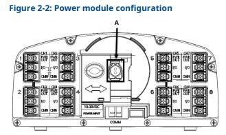 A. Plastic plug
 - Remove the plastic plug from the receptacle.
- Power the device in one of two ways:
• Install the 701P SmartPower Module into the 802 Transmitter to power the device.
• Move the mechanical slider to expose the external power supply terminals and power the transmitter with a 10-30 Vdc power source.
Input voltage 10-30 Vdc
Input current (maximum) 805 mA
Power supply must be isolated from AC mains and provide transient free DC input power to the transmitter.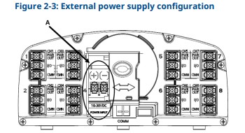
2.2 Antenna position
Position the antenna vertically, approximately 3 ft. (1 m) away from any large structure, building, or conductive surface to allow for clear communication to other devices. 2.3 Plug conduits
Procedure
Plug the unused conduit entries with supplied conduit plugs with approved sealant.
Provisioning & commissioning
3.1 Provision transmitter
Prerequisites
You must power up the transmitter before the communication device can interface with the it. For HART® wireless transmitter communication via a communication device, an 802 wireless device descriptor (DD) is required.
Procedure
To obtain the latest DD, go to Software & Drivers. A. Communication terminals
Note
The Emerson 475 Field Communicator will not work as a communication device for the 802 Transmitter.
3.2 Commission transmitter to Gateway
If you ordered the transmitter with a factory-configured network ID and join key, it should join the network with no user input.
If you’re unsure if you ordered the device with the factory-configured option, you can manually enter the network ID and join key to match the Gateway.
Procedure
- To obtain the network ID and join key, go to Network → Network Settings in the Gateway user interface.
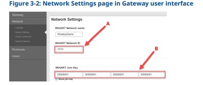 A. Network ID
B. Join Key - Use communication device or HART® modem to configure the transmitter by entering the network ID and join key, as shown in Figure 3-1.
Note
It may take several minutes for the device to join the network.
Terminal wiring for input and output circuits
The transmitter has three screw terminals for each channel.
These terminals are labeled as follows:
PWR OUT Constant power out
I/O Switched input or output channel
CMN Common
Note
All eight channels have a third PWR OUT terminal that outputs continuous voltage which can be up to 2 Vdc less than the supplied external power to the transmitter. (For example, 28 Vdc into the transmitter, PWR OUT terminal outputs 26 Vdc)
4.1 Discrete inputs
Note
Optionally, you can use the device to invert any input to change the discrete logic state. This is useful, for instance, if a normally open switch is used to replace a normally closed switch.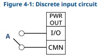 A. Dry contact only
4.2 Discrete output switch functionality
The host control system drives the discrete output of the 802 Transmitter through the Wireless Gateway and out to the transmitter.
The time required for wireless communication from the Gateway to the transmitter is dependent on many factors, including the size and topology of the network and the total amount of ownstream traffic on the wireless network. For a network that is constructed to Emerson’s best practices, typical delays in communication of a discrete output from the Gateway to the transmitter are 15 seconds or less. Remember that this delay is only part of the latency that will be observed in a control loop.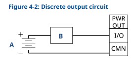 A. External power supply
B. Load
4.3 Alternative discrete output functionality
All eight channels have a third PWR OUT terminal that outputs continuous voltage, which can be up to 2 Vdc less than the supplied external power to the transmitter. (For example, if the external power supplies 28 Vdc to the transmitter, the PWR OUT terminal will output 26 Vdc.)
Figure 4-3 shows the alternative wiring configuration. A. Load
4.4 Special considerations for multi-output circuits
Important
If more than one channel is connected to output circuits, it is very important that the CMN terminal of each circuit be at the same voltage. Employing a common ground for all output circuits is one way to ensure that all circuits have CMN terminals at the same voltage.
If two output circuits are connected to a single transmitter with a single power supply, both input/output (I/O) and common (CMN) terminals must be connected to each output circuit. The negative power supply wires must be at the same voltage and connected to both CMN terminals. 4.5 Switching greater currents or voltages
Note
Maximum switching capacity is 28 Vdc and 100 mA per channel. If you need to switch a greater voltage or current, use an interposing relay circuit.
Figure 4-5 shows an example of a circuit to switch higher currents or voltages.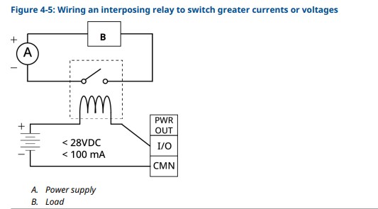
Mount transmitter remotely
Emerson has designed the 802 Transmitter to be installed only in the remote mount configuration, where the sensor is mounted separately from the housing and then connected to the transmitter via conduit.
Procedure
- Install the transmitter according to standard installation practices.
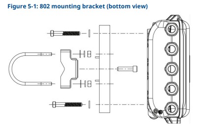
Make sure to use thread sealant on all connections. - To reduce sensor wiring length, mount the transmitter centrally to all of the measurements. When installing the transmitter, make sure the conduit entries are facing downward. If using the mounting bracket (option code B6), mount the transmitter to a 2-in. (51 mm) pipe.
Postrequisites
For additional remote mounting information, see Emerson.com.
Grounding the transmitter
The transmitter operates best with the housing grounded
Floating systems, however, can cause extra noise that may affect the accuracy of the transmitter.
If the signal appears noisy or erratic, grounding at a single point may solve the problem. Ground the transmitter through the process connection using the internal or external grounding terminal.
Product certifications
Revision 2.5
7.1 European Directive information
A copy of the EC Declaration of Conformity can be found at the end of the Quick Start Guide. The most recent revision of the EC Declaration of Conformity can be found at Emerson.com/Rosemount.
7.2 Telecommunication compliance
All wireless devices require certification to ensure they adhere to regulations regarding the use of the radio frequency (RF) spectrum. Nearly every country requires this type of product certification.
Emerson is working with governmental agencies around the world to supply fully compliant products and remove the risk of violating country directives or laws governing wireless device usage.
7.3 Federal Communications Commission (FCC) and Innovation, Science, and Economic Development Canada (ISED)
This device complies with Part 15 of the FCC Rules. Operation is subject to the following conditions: This device may not cause harmful interference; this device must accept any interference received, including interference that may cause undesired operation. This device must be installed to ensure a minimum antenna separation distance of 7.9 in. (20 cm) from all persons.
This device contains license-exempt transmitter(s)/receiver(s) that comply with Innovation, Science, and Economic Development Canada’s license exempt RSS(s). Operation is subject to the following two conditions:
- This device may not cause interference.
- This device must accept any interference, including interference that may cause undesired operation of the device.
Changes or modification to the equipment not expressly approved by Emerson could void the user’s authority to operate the equipment.
7.4 Ordinary location certification
As standard, the transmitter has been examined and tested to determine that the design meets the basic electrical, mechanical, and fire protection requirements by a Nationally Recognized Test Laboratory (NRTL), as accredited by the Federal Occupational Safety and Health Administration (OSHA).
7.5 Installing in North America
The US National Electrical Code®
(NEC) and the Canadian Electrical Code (CEC) permit the use of
Division marked equipment in Zones and Zone marked equipment in Divisions.
The markings must be suitable for the area classification, gas, and temperature class. This information is clearly defined in the respective codes.
7.6 USA
7.6.1 N5 USA Division 2, Non-Incendive
| Certificate | FM24US0017X |
| Markings | NI Class I, Division 2, Groups A, B, C, D T4 (-50 °C ≤ Ta ≤ +70 °C) |
Field wiring shall be rated for +172 °F (+78 °C).
Enclosure Type 4X/IP66
Specific Conditions for Safe Use (X):
Only the Emerson SmartPower™ 701PBKKF shall be used for replacement.
7.7 Canada
7.7.1 N6 Canada Division 2, Non-Incendive
| Certificate | FM24CA0008X |
| Markings | NI Class I, Division 2, Groups A, B, C, D T4 (-50 °C ≤ Ta ≤ +70 °C) |
Field wiring shall be rated for +172 °F (+78°C).
Enclosure Type 4X/IP66
Specific Conditions for Safe Use (X):
Only the Emerson SmartPower™ 701PBKKF shall be used for replacement.
7.8 Declaration of Conformity
EU DECLARATION OF CONFORMITY
This declaration of conformity is issued under the sole responsibility of that the following products,
Rosemount Inc. 6021 Innovation Blvd Shakopee, MN 55379 USA
Rosemount™ 802 Wireless Multi Discrete I/O Transmitter comply with the provisions of the European Union Directives, including the latest amendments, valid at the time this declaration was signed.
Mark Lee Vice President, Quality (name) (function) Boulder, CO, USA (place of issue)
Authorized Representative in Europe: Emerson S.R.L., company No. J12/88/2006 Emerson 4 street, Parcul Industrial Tetarom II, Cluj-Napoca 400638, Romania
Regulatory Compliance Shared Services Department
Email: europeproductcompliance@emerson.com Phone: +40 374 132 035
EMC Directive (2014/30/EU)
Harmonized Standards:
EN 61326-1:2021
RED Directive (2014/53/EU)
Harmonized Standards:
EN 300 328 V2.2.2
EN 301 489-1 V2.2.3
EN 301 489-17 V3.2.4
EN 62311:2020
For more information: Emerson.com/global
©2024 Emerson. All rights reserved.
Emerson Terms and Conditions of Sale are available upon request. The Emerson logo is a trademark and service mark of Emerson Electric Co.
Rosemount is a mark of one of the Emerson family of companies. All other marks are the property of their respective owners.
![]() Quick Start Guide
Quick Start Guide
MS-00825-0100-4082, Rev. AA
March 2024![]()
Documents / Resources
 |
EMERSON 802 Wireless Multi Discrete I O Transmitter [pdf] User Guide 802, 802 Wireless Multi Discrete I O Transmitter, 802, Wireless Multi Discrete I O Transmitter, Multi Discrete I O Transmitter, Discrete I O Transmitter, I O Transmitter, O Transmitter, Transmitter |