![]() LINK-E – User Manual
LINK-E – User Manual
WI-FI MODULE FOR REMOTE CONNECTION PRO SERIES CONTROL BOARDS
GENERAL OVERVIEW
This manual must always accompany the relevant equipment and be kept in an accessible location for consultation by qualified technicians involved in the operation and maintenance of the system. The installer/user is strongly recommended to carefully read all instructions and information in this manual before using the product, in order to avoid damage or improper use of the unit, which would also render the warranty null and void.
Before operating the equipment, carefully read the manual and follow all instructions provided.
The information and instructions in this manual refer to the standard use of this product; in the event of special circumstances, functions or applications not described in this document, please contact our service centre for assistance.
If technical assistance or spare parts are required, when contacting the manufacturer always specify the identification code of the model and construction number as stated on the data plate. Our service centre is available for any requirement or clarification.
On receipt of the equipment, inspect it immediately to ensure that it has not been damaged during transport. If defects are found, the client should promptly notify, within 5 days of receiving the goods, our retailer or in the event of direct purchases, the manufacturer’s service centre.
![]() N.B. the information provided in this manual is subject to modifications without notice. The manufacturer shall not be held responsible for any damage resulting from the use of this manual, as it is intended as a guide only.
N.B. the information provided in this manual is subject to modifications without notice. The manufacturer shall not be held responsible for any damage resulting from the use of this manual, as it is intended as a guide only.
Note that failure to observe the instructions provided in this manual may cause physical injury or damage to objects. In any event all local and/or current legislation must be observed at all times.
WARNINGS
![]() The control board must be used exclusively for the purpose and function as specified in design.
The control board must be used exclusively for the purpose and function as specified in design.
Any other application or use is to be considered improper and therefore hazardous.
In the event of a fire at the installation site or in the surrounding area, avoid the use of water jets and use appropriate extinguishing equipment and agents (powder, foam, carbon dioxide).
Install the equipment far from heat sources and in a dry and sheltered location according to the specified protection rating (IP).
The installation of a safety device is recommended to protect the board power line in compliance with current electrical safety standards.
Before performing any work on the electrical panel or system, disconnect the electrical power supply.
No parts of the panel should be removed without an official authorisation from the manufacturer: any tampering with or changes to the unit will render all terms of the warranty null and void.
All installation and/or maintenance operations must be performed by a specialised technician who is fully aware of the currently applicable safety standards.
Ensure that the installation is connected to an efficient earthing system.
After completing the electrical connection, check that all electrical panel settings are correct to avoid automatic start-up of the electric pump.
The manufacturer declines all liability in the event of the following:
– Incorrect installation;
– Use by personnel not adequately trained in the correct use of the panel;
– Serious failure to perform scheduled maintenance;
– Use of non-original spare parts or parts not model-specific;
– Unauthorised modifications or interventions;
– Partial or total failure to observe instructions.
GENERAL DESCRIPTION
3.1 Operation
The LINK_E Wi-Fi remote connection module allows all PRO series electronic boards to be controlled via RS-485 serial connection and MODBUS communication protocol.
In order to operate, the PROXPS-RS485 expansion unit must be installed on the motherboard and the software version must be V2.0 or higher.
3.2 Technical specifications
- Power supply 11-28Vdc;
- Current consumption 150mA – 300mA;
- Integrated IoT module.
- DIN rail mounting (1.5 slots).
- WiFi 2.4G connection.
- RS485 master or slave interface.
- RGB status LED.
- Reset and configuration button.
- Integration with Iot Stream cloud platform.
- Box in ABS, IP00;
- Ambient temperature: -5/+40 °C;
- Relative humidity 50% at 40 °C (condensate free).
3.3 Main functions
- Data acquisition via Modbus protocol.
- Remote device monitoring and control.
- Transmission of parameter change commands.
- FOTA functionality for remote gateway update.
- Remote device firmware update.
- Data encryption for communication security.
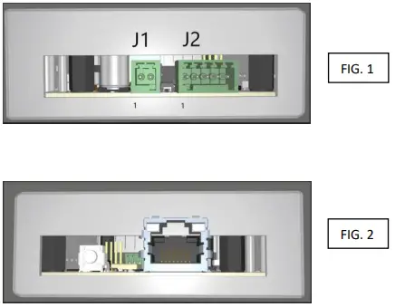
3.4 Interfaces and connections
- 1 RJ-45 Ethernet connector (FIG. 2)
- 1 RGB status LED
- 1 Reset button
- 1 Mains power connector (J1) (FIG. 1):
➢ Pin 1: GND
➢ Pin 2: +DC - 1 Communication connector on EIA RS-485 bus (J2) (FIG. 1):
➢ Pin 1: Terminating resistor *
➢ Pin 2: Terminating resistor *
➢ Pin 3: GND
➢ Pin 4: A
➢ Pin 5: B
* To insert the terminating resistor, simply make a connection between pin 1 and 2
INSTALLATION
Ensure that the mains power supply specifications correspond to the voltage specified on the data plate of the electrical panel, then make the earthing connection before all other connections. 1~100-240Vac 50/60Hz
The power line must be protected by a residual current circuit breaker.
The module is designed for DIN rail mounting.
Install the unit in locations that conform to the required protection rating.
LED INDICATORS AND COMMANDS
5.1 Reset button
The reset button can be used to restart the device.
If pressed for more than 30 seconds, it clears the connection data and goes into ‘Captive Portal’ mode.
5.2 RGB status LED
| Green LED, Solid – Normal operation status, device is connected to the internet | |
| Green LED, Flashing – WiFi/Ethernet connection in progress | |
| Blue LED, Solid – ‘Captive Portal’ mode in progress | |
| White LED, Solid – Maintenance mode | |
| White LED, Flashing – Firmware update in progress | |
| Yellow LED, Solid – Cloud connection absent warning | |
| Yellow LED, Flashing – No internet connection warning. | |
| Red LED, Solid – Critical error |
QUICK START GUIDE
6.1 Requirements
➢ A smartphone for setting up the WiFi connection
➢ A DC power supply with an output voltage ranging from 11 to 28 VDC
➢ Wifi module with LTE connection ( in the absence of a local WiFi network) and 2.4G frequency
➢ Disable any firewall restrictions
6.2 Gateway configuration
➢ WiFi connection
- When first switched on, the device generates a WiFi network called ‘IOT CAPTIVE PORTAL’.
 Connect to the IOT CAPTIVE PORTAL network. The first time you connect you may be asked for a password: type 12345678
- Open a browser page and type IP 192.168.4.1
- The connecting user will automatically be redirected to a web page for network configuration:
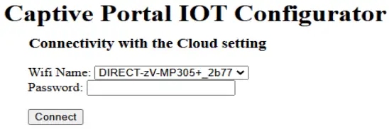
- Select the name of the WiFi network to be used by the device, enter the password of the selected WiFi network and press the ‘Connect’ button.
The device will now attempt to connect to the selected network and thus to the cloud platform.
If the connection is unsuccessful, the configuration WiFi network (‘IOT CAPTIVE PORTAL’) will be regenerated
 Once connected to the Internet, via Ethernet or WiFi, the device will start communicating data to the ‘IoT Platform’.
6.3 Registration on the IoT Stream platform
Using your browser, go to https://iot.stream/registration, where the following interface will appear where you can enter your registration data.

Fill in the mandatory data and enter the serial number of your gateway; click on the ‘Register’ button and you will receive an email from the @IOT.STREAM platform with a registration confirmation code and the USERNAME to be entered, together with the password created, to access the control platform.
ALARMS
In the event of an alarm or error, the following lights up:
![]() Red LED, Solid – Critical error
Red LED, Solid – Critical error
If this occurs, please contact your dealer.
STANDARD DIMENSIONS

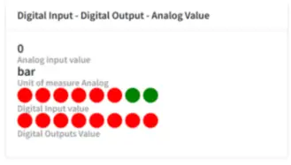
INTERFACE
- After registering, proceedwith logging in to theplatform by entering yourusername and password.
Complete the ‘Captchacheck’, then log in bypressing the ‘Login’ button
- Select which system to monitor from those connected and online
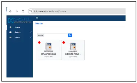
- The tab displayed shows the data and settings of the control board connected via the LINK-E GATEWAY. You can zoom in on the page depending on the size of the device used or your requirements.

- The platform is arranged in several tabs, grouping and displaying the various parameters (see the user manual of the connected control board for respective meanings).
1 Red indicates the current status of the parameter/function.
2 total number of parameters (including those not displayed) shown on the tab.
3 button to access and edit all parameters shown on the tab
4 single parameter edit
5 button for submitting changes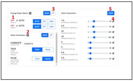
- Confirmation request message for submitting changed parameters; once confirmed press OK on the next message

- The input/output status tab shows the status of the floats and/or probes and the status of the motor control outputs. When red the input/output is open; when green the input/output is closed
DIAGNOSTICS
| PROBLEM | CHECKS/SOLUTIONS |
| THE IOT CAPTIVE PORTAL NETWORK IS NOT PRESENT IN THE WIFI NETWORK LIST |
• Switch the LINK-E off and on again. • Press the external button for 30 seconds. |
| LINK-E IS ONLINE BUT IS NOT COMMUNICATING WITH THE CONTROL BOARD | • Check that the MODBUS address of the switchboard board is set to 10 (refer to the switchboard manual) |
| CANNOT CONNECT TO WIFI NETWORK | • Check that the WIFI network in use is set to 2.4GHz frequency. • Check and possibly override any firewall restrictions |
![]() ELENTEK SRL SOCIETÀ UNIPERSONALE
ELENTEK SRL SOCIETÀ UNIPERSONALE
Via A. Meucci 5/11 – 35028 Piove di Sacco (PD) – ITALY
Ph. +39 049 9730367 – Fax +39 049 9731063
www.elentek.com
info@elentek.com
VAT No. 04534630282
Cod. MQ 0056 UK
Rev. 00
Issued 01.2025
Documents / Resources
 |
elentek LINK-E WiFi Module For Remote Connection Pro Control Boards [pdf] User Manual LINK-E WiFi Module For Remote Connection Pro Control Boards, LINK-E, WiFi Module For Remote Connection Pro Control Boards, Remote Connection Pro Control Boards, Connection Pro Control Boards, Control Boards |