Edge-core EAP112 Wi-Fi 6 IoT
Gateway User Guide

Package Contents
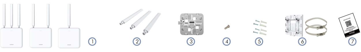
- EAP112, EAP112-L, EAP112-H Wi-Fi 6 IoT Gateway
- External antennas (3 for EAP112, 2 for EAP112-L, and 1 for EAP112-H)
- Mounting bracket accessory
- Mounting bracket security screw
- Screw kit–4 screws and 4 plugs
- (Option) Pole-mount kit–bracket and 2 steel-band hose clamps
- QR code card
Overview
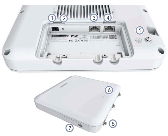
- 12 VDC power input
- Restart/Reset button:
A quick press restarts the system.
Press and hold for 5 seconds resets to factory defaults. - Uplink (PoE) Port: 10/100/1000BASE-T, 802.3at PoE
- LAN Port: 10/100/1000BASE-T
- Ground screw
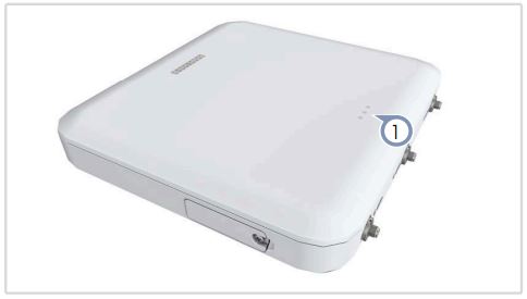
- System LED Indicators:
(Left) Green: On (power/Wi-Fi OK), Blinking (Wi-Fi traffic)
(Center) Blue: On (LTE), Blinking (LTE traffic)
(Right) Orange: On (HaLow), Blinking (HaLow traffic) - SIM card slot access panel
- External antenna connectors (3 for EAP112, 2 for EAP112-L, and 1 for EAP112-H)
Installation
1 Mount the AP
a. Mounting on a Wall
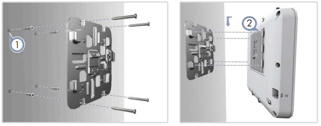
- At the installation location on the wall, use the mounting bracket to mark four holes for the wall plugs and screws (included in the screw kit). Drill four holes for the wall plugs, and then insert the plugs and tap them flush with the wall surface.
Note: Drill 2.5 mm (±0.2 mm) holes for M3 self-tapping screws, or 4.5 mm (±0.2 mm) holes for nylon wall plugs.
Use the four screws to secure the bracket to the wall. - With its ports facing down, place the AP over the bracket flanges
and then slide it down until it snaps into its secured position.
b. Mounting on a Ceiling Without T-Bars
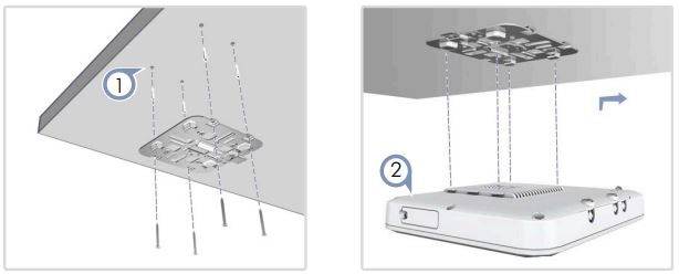
- At the installation location on the ceiling, use the mounting bracket to mark four holes for the plugs and screws (included in the screw kit).
Drill four holes for the plugs, and then insert the plugs and tap them flush with the ceiling surface.
Use the four screws to secure the bracket to the ceiling (screw torque must be less than 6 kgf.cm). - Place the AP over the bracket flanges and then slide it onto the bracket until it snaps into its secured position.
c. (Optional) Mounting on a Pole (max. 2.5 inch diameter)

- Slide the pole-mount bracket onto the base of the AP until it clicks into its locked position.
- Feed the two steel-band clamps through the pole-mount bracket mounting points.
- Fasten the steel-band clamps around the pole to secure the AP to the pole.
2 Install External Antennas
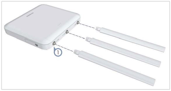
- Attach the external antennas to the connectors on the AP (3 for EAP112, 2 for EAP112-L, and 1 for EAP112-H).
3 Connect Cables
a. Connect LAN Cables

- Connect Category 5e or better cable to the Uplink (PoE) 1000BASE-T RJ-45 port. When connected to a PoE source, the Uplink (PoE) port connection provides power to the unit.
- (Optional) Connect a local LAN switch or computer to the LAN 1000BASE-T RJ-45 port.
b. (Optional) Connect AC Power Adapter
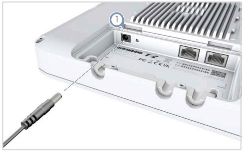
- When not connected to a PoE source, connect the AC power adapter to the DC power jack on the AP and then plug the adapter into a nearby AC power source.
4 Check the System LEDs
- When operating normally, the green, blue, and orange LEDs should be on. Blinking LEDs indicate network activity.
5 Connect to the Web User Interface
- Connect a PC directly to the AP’s LAN port.
- Set the PC IP address to be on the same subnet as the AP LAN port default IP address. (The PC address must start 192.168.2.x with subnet mask 255.255.255.0.)
- Enter the AP’s default IP address of 192.168.2.1 into the web browser address bar.
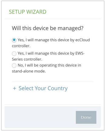
Note: To connect to the web interface using the Uplink (PoE) port, the IP address is automatically assigned through DHCP by default. If a DHCP server is unreachable, the Uplink (PoE) port reverts to a fallback IP address of 192.168.1.10. - On first-time log in to the web interface, the Setup Wizard starts and you must select how the AP will be managed, either using the ecCLOUD controller, an EWS-Series controller, or in stand-alone mode.
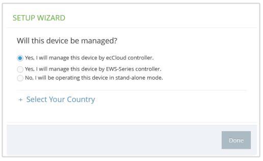
- Continue with the Setup Wizard to make other settings: Cloud-Managed Mode: Select the country of operation.
EWS-Series Controller Mode: Complete the CAPWAP setup, use the default wireless network setting or customize the network name, then set a password (the default user name is “admin” with password “admin”), and select the country of operation.
Stand-Alone Mode: Use the default wireless network setting or customize the network name, then set a password (the default user name is “admin” with password “admin”), and select the country of operation. - Click “Done” to finish the setup wizard.
Note: For more information on the Setup Wizard and AP configuration, refer to the User Manual.
6 (Optional) QR Code Onboarding
For quick set up and registration of your AP with the ecCLOUD controller, you can scan the QR code on the AP using a phone.
Follow these steps:
- Make sure the AP is powered on and connected to the Internet.
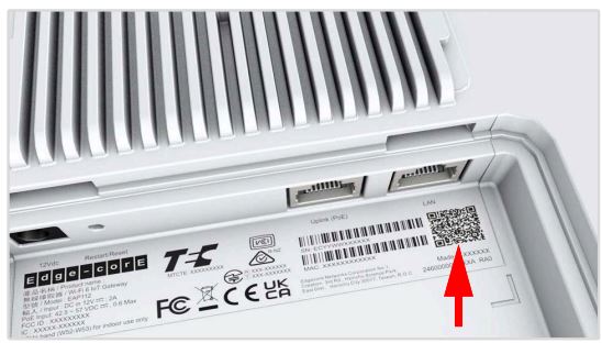
- Use the camera (iPhone) or a barcode app (Android) on your phone to scan the AP’s QR code. The QR code is printed on a label next to the AP’s ports.
- When a message pops up, tap “yes” to join the Wi-Fi network (iPhone requires you to go to Settings > Wi-Fi or open the browser for the message to pop up). The web browser should open and redirect to the Setup Wizard page.
Note: If the phone cannot connect to the Wi-Fi network, type the SSID (network name) and password manually. The SSID name is the AP serial number (for example, EC0123456789), and the password is the AP MAC address (for example, 903CB3BC1234). - After setting a new password and the regulatory country, select to manage the AP using the ecCLOUD controller, an EWS-Series controller, or to manage the AP in stand-alone mode.
a. Stand-Alone Mode: Use the default wireless network setting or customize the network name and password. Tap “Done” to finish the Setup Wizard. Wait about two minutes for the AP configuration to update, and then connect to the wireless network name configured in the setup wizard. The browser is then redirected to the login page of the AP.
b. EWS-Series Controller Mode: Complete the CAPWAP setup, then set a password and select the country of operation. Tap “Done” to finish the setup wizard.
c. Cloud-Managed Mode: Tap “Done” to finish the setup wizard and the browser is redirected to the ecCLOUD login page.

If you already have an ecCLOUD account, log in and select a site for the AP. The AP is automatically registered for cloud management. After you tap “Save,” wait about two minutes for the cloud controller to configure the AP.

If you do not have an ecCLOUD account, tap “I want to register” and first set up an account. Create a cloud and site before confirming the regulatory country. After tapping “Next,” the AP is then automatically registered for cloud management. After you tap “Save,” wait about two minutes for the cloud controller to configure the AP.
Note: Refer to the Edgecore ecCLOUD Controller User Manual for more information on setting up and configuring APs through ecCLOUD.
Safety and Regulatory Information
FCC Class B
This equipment has been tested and found to comply with the limits for a Class B digital device, pursuant to Part 15 of the FCC Rules. These limits are designed to provide reasonable protection against harmful interference in a residential installation. This equipment generates, uses and can radiate radio frequency energy and, if not installed and used in accordance with the instructions, may cause harmful interference to radio communications. However, there is no guarantee that interference will not occur in a particular installation. If this equipment does cause harmful interference to radio or television reception, which can be determined by turning the equipment off and on, the user is encouraged to try to correct the interference by one of the following measures:
- Reorient or relocate the receiving antenna
- Increase the separation between the equipment and receiver
- Connect the equipment into an outlet on a circuit different from that to which the receiver is connected
- Consult the dealer or an experienced radio/TV technician for help
FCC Caution: Any changes or modifications not expressly approved by the party responsible for compliance could void the user’s authority to operate this equipment.
This device complies with Part 15 of the FCC Rules. Operation is subject to the following two conditions: (1) This device may not cause harmful interference, and (2) this device must accept any interference received, including interference that may cause undesired operation.
For product available in the USA/Canada market, only channel 1~11 can be operated. Selection of other channels is not possible.
IMPORTANT NOTE:
FCC Radiation Exposure Statement:
This equipment complies with FCC radiation exposure limits set forth for an uncontrolled environment. This equipment should be installed and operated with minimum distance 20 cm between the radiator and your body.
Professional Installation Instructions
- Installation personnel This product is designed for specific applications and should be installed by qualified personnel who have knowledge of RF and its related regulations. A general user shall not attempt to install or modify the equipment configuration.
- Installation location To meet regulatory RF exposure requirements, this product shall be installed at a location where, during normal operations, the radiating antenna is at least 20 cm away from any nearby persons.
- External antenna Use only the antennas which have been approved by the applicant. Using non-approved antenna(s) is prohibited and may produce unwanted spurious or excessive RF transmitting power which may lead to a violation of FCC limits.
- Installation procedure Please refer to this equipment’s user manual for the procedure details.
- Warning The installation position must be carefully selected so that the final output power does not exceed the limit set forth in relevant regulations. Violation of output power regulations could lead to serious federal penalties.
CE Statement
This equipment complies with EU radiation exposure limits set forth for an uncontrolled environment. This equipment should be installed and operated with minimum distance 20 cm between the radiator and your body.
The device is restricted to indoor use only when operating in the 5150 to 5350 MHz frequency range.
All operational modes:
2.4 GHz: 802.11b, 802.11g, 802.11n (HT20), 802.11n (HT40), 802.11ac (VHT20), 802.11ac (VHT40), 802.11ax (HE20), 802.11ax (HE40)
5 GHz: 802.11a, 802.11n (HT20), 802.11n (HT40), 802.11ac (VHT20), 802.11ac (VHT40), 802.11ac (VHT80), 802.11ax (HE20), 802.11ax (HE40), 802.11ax (HE80)
BLE 2.4 GHz: 802.15.1
The frequency and maximum transmitted power limit in EU are listed as below:
2412-2472 MHz: 20 dBm 5150-5350 MHz: 23 dBm 5500-5700 MHz: 30 dBm

The abbreviations of the countries, as prescribed in above table, where any restrictions on putting into service or any requirements for authorization of use exist.
![]() CE Mark Declaration of Conformance for EMI and Safety (EEC) This information technology equipment is in compliance with the Directive 2014/53/EU and Directive 2014/35/EU. The Declaration of Conformity (DoC) can be obtained from www.edgecore.com -> support -> download.
CE Mark Declaration of Conformance for EMI and Safety (EEC) This information technology equipment is in compliance with the Directive 2014/53/EU and Directive 2014/35/EU. The Declaration of Conformity (DoC) can be obtained from www.edgecore.com -> support -> download.
Japan VCCI Statement
Warnings and Cautionary Messages
![]() Warning: This product does not contain any serviceable user parts.
Warning: This product does not contain any serviceable user parts.
Warning: Installation and removal of the unit must be carried out by qualified personnel only.
⚠ Caution: Wear an anti-static wrist strap or take other suitable measures to prevent electrostatic discharge when handling this equipment.
Caution: Do not plug a phone jack connector in the RJ-45 port. This may damage this device.
Caution: Use only twisted-pair cables with RJ-45 connectors that conform to FCC standards.
Hardware Specifications
AP Chassis
Size (WxDxH) 210 x 195 x 40 mm (8.27 x 7.68 x 1.57 in.)
Weight 1.14 kg (2.51 lb)
Temperature Operating: -30° C to 50° C (-22° F to 122° F)
Storage: -40° C to 60° C (-40° F to 140° F)
Humidity Operating: 5% to 95% (non-condensing)
Waterproof Rating IP65
Network Interfaces
Ports Uplink (PoE) RJ-45 Port: 1000BASE-T, PoE PD
LAN RJ-45 Port: 1000BASE-T
2.4 GHz Radio IEEE 802.11b/g/n/ac/ax
5 GHz Radio IEEE 802.11a/ac/n/ax
HaLow Radio
(EAP 112 &
EAP112-H only)
IEEE 802.11ah
Bluetooth Radio IEEE 802.15.1
Radio Frequencies 2.4–2.4835 GHz (US, ETSI, Japan)
5.15–5.25 GHz (lower band) US
5.250–5.320 GHz (DFS band) US
5.470–5.725 GHz (DFS band) US
5.725–5.825 GHz (upper band) US
Europe:
5.15–5.25 GHz, 5.25–5.35, 5.47–5.725 GHz Japan:
5.15–5.25 GHz, 5.25–5.35, 5.47–5.73 GHz
HaLow (EAP112 & EAP112-H only):
Halow (FCC): 902–928 MHz
Halow (CE): 863–868 MHz
Halow (JP): 923–927 MHz
LTE (EAP112 & EAP112-L only):
LTE-FDD (US/ETSI/Japan) B1/B2/B3/B4/B5//B7/
B8/B12/B13/B14/B17/B18/B19/B20/B25/B26/
B28/B29/B30/B32/B66/B71
LTE-TDD (US/ETSI/Japan) B34/B38/B39/B40/
B41/B42/B43/B46(LAA)/B48(CBRS)
WCDMA (US/ETSI/Japan) B1/B2/B3/B4/B5/B6/
B8/B19
Power Specifications
Radio EN300 328 V2.2.2 (2019-07)
EN301 893 V2.1.1(2017-05)
EN300 220: HaLow
47 CFR FCC Part 15.247
47 CFR FCC Part 15.407
MIC certification Rule, Article 2 Paragraph 1 Item 19
MIC certification Rule, Article 2 Paragraph 1 Item 19-3
Emissions EN 301 489-1 V2.2.3 (2019-11)
EN 301 489-17 V3.2.4 (2020-09)
EN 301 489-3/-52 V1.2.1 (2021-11)
EN 55032/35 A1/A11 2020
47 CFR FCC Rules and Regulations Part 15
Subpart B, Class B Digital Device
Certification, Article 3, Article 4, Article 6, Article 9 and Article 34 regulation
Safety Low Voltage Directive IEC 62368-1:2014;and/or
EN 62368-1:2014+A11:2017; and/or BS
62368-1:2014+A11:2017
IEC/EN 62368-1, IEC/EN 60950-1
Documents / Resources
 |
Edge-core EAP112 Wi-Fi 6 IoT Gateway [pdf] User Guide EAP112, EAP112 Wi-Fi 6 IoT Gateway, Wi-Fi 6 IoT Gateway, 6 IoT Gateway, Gateway |