Edge-core AS7926-40XKFB 100G Aggregation Router User Guide

Package Contents
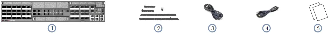
- AS7926-40XKFB
- Rack mounting kit
- 2 x Power cord
- Console cable—RJ-45 to D-Sub
- Documentation—Quick Start Guide (this document) and Safety and Regulatory Information
Overview
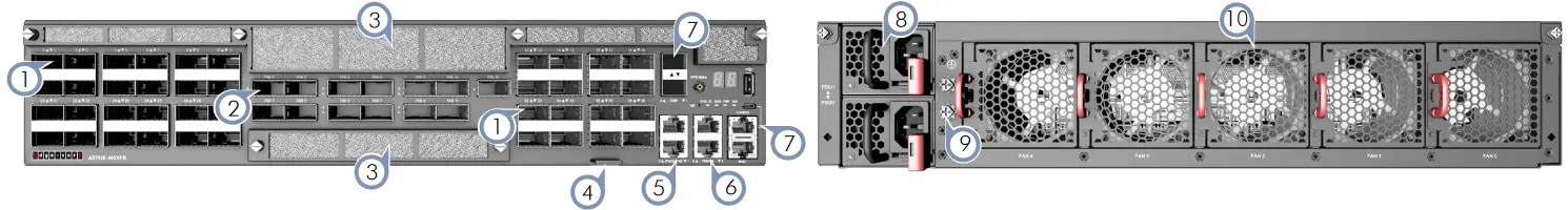
- 40 x 100G QSFP28 ports
- 13 x 400G QSFP-DD fabric ports
- Air filters
- Product tag
- 2 x RJ-45 Stack-Sync ports
- Timing Ports: 2 x RJ-45 PPS/ToD, 1PPS/10MHz connector
- Management I/O: 1000BASE-T RJ-45, 2 x 10G SFP+, RJ-45/
Micro USB console, USB storage, reset button, 7-segment display - 2 x AC PSUs
- Grounding screw
- 5 x fan trays
Status LEDs
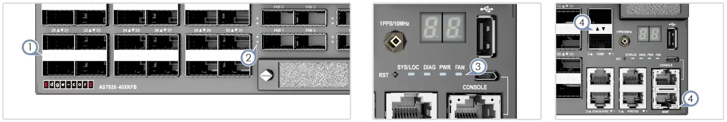
- QSFP28 Port LEDs:
■ Blue — 100G
■ Yellow — 40G
■ Cyan — 2 x 50G
■ Magenta — 4 x 25G
■ Green — 4 x 10G - QSFP-DD Port LEDs:
■ Blue — 400G - System LEDs:
■ SYS/LOC — Green (OK)
■ DIAG — Green (OK), Red (fault detected)
■ PWR — Green (OK), Amber (fault)
■ FAN — Green (OK), Amber (fault) - Management Port LEDs:
■ SFP+ OOB Port — Green (10G), Amber (1G)
■ RJ-45 OOB Port — Right (link), Left (activity)
FRU Replacement

PSU Replacement
- Remove the power cord.
- Press the release latch and remove the PSU.
- Install replacement PSU with matching airflow direction.

Fan Tray Replacement
- Press the release latch in the fan tray handle.
- Pull out to remove the fan.
- Install replacement fan with matching airflow direction.
Air Filter Replacement

Air Filter Replacement
- Unscrew the filter cover captive screws.
- Remove the old filter and install a replacement filter.
- Replace the filter cover and tighten the captive screws.
![]()
Installation
![]() Warning: For a safe and reliable installation, use only the accessories and screws provided with the device. Use of other accessories and screws could result in damage to the unit. Any damages incurred by using unapproved accessories are not covered by the warranty.
Warning: For a safe and reliable installation, use only the accessories and screws provided with the device. Use of other accessories and screws could result in damage to the unit. Any damages incurred by using unapproved accessories are not covered by the warranty.
![]() Caution: The server includes plug-in power supply (PSU) and fan tray modules that are installed into its chassis. Make sure all installed modules have a matching airflow direction (front-to- back).
Caution: The server includes plug-in power supply (PSU) and fan tray modules that are installed into its chassis. Make sure all installed modules have a matching airflow direction (front-to- back).
![]() Note: The server has the Open Network Install Environment (ONIE) software installer preloaded on the switch, but no switch software image. Information about compatible switch software can be found at www.edge-core.com.
Note: The server has the Open Network Install Environment (ONIE) software installer preloaded on the switch, but no switch software image. Information about compatible switch software can be found at www.edge-core.com.
![]() Note: The switch drawings in this document are for illustration only and may not match your particular switch model.
Note: The switch drawings in this document are for illustration only and may not match your particular switch model.
1 Mount the Switch

1. Use the included screws to attach the rack mount bracket to each side of the switch.

2. For each rack-rail assembly, adjust the rear slide plate to the position marked as 630mm.
3. Secure it in place by fastening the thumbscrew.
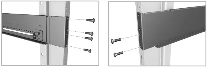
4. Extend each rack-rail assembly until it fits the rear post and the front post of the rack.
5. Secure each rack-rail assembly using four screws on the rear post and two on the front post.

6. Slide the switch into the rack until it connects with the front post.
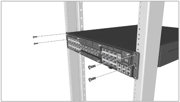
7. Secure the switch in the rack using two screws on each rack mount bracket.
2 Ground the Switch

Verify Rack Ground
Ensure the rack on which the switch is to be mounted is properly grounded and in compliance with ETSI ETS 300 253. Verify that there is a good electrical connection to the grounding point on the rack (no
paint or isolating surface treatment).
Attach Grounding Wire
Attach a lug (not provided) to a #8 AWG minimum grounding wire (not provided), and connect it to the grounding point on the switch rear panel. Then connect the other end of the wire to rack ground.
![]() Caution: The chassis ground connection must not be removed unless all supply connections have been disconnected.
Caution: The chassis ground connection must not be removed unless all supply connections have been disconnected.
![]() Caution: The device must be installed in a restricted- access location. It should have a separate protective ground terminal on the chassis that must be permanently connected to a well grounded chassis or frame to adequately ground the device chassis and protect the operator from electrical hazards.
Caution: The device must be installed in a restricted- access location. It should have a separate protective ground terminal on the chassis that must be permanently connected to a well grounded chassis or frame to adequately ground the device chassis and protect the operator from electrical hazards.
3 Connect Power
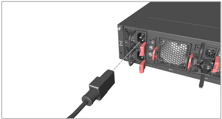
AC Power
Install two AC PSUs and then connect them to an AC power source.
![]() Note: When using only one AC PSU to power a fully loaded system, be sure to use a high-voltage source (200-240 VAC).
Note: When using only one AC PSU to power a fully loaded system, be sure to use a high-voltage source (200-240 VAC).
DC Power
Install two DC PSUs and then connect them to a DC power source.
![]() Caution: Use a IEC/UL/EN 60950-1 and/or 62368-1 certified power supply to connect to a DC converter.
Caution: Use a IEC/UL/EN 60950-1 and/or 62368-1 certified power supply to connect to a DC converter.
![]() Caution: All DC power connections should be performed by a qualified professional.
Caution: All DC power connections should be performed by a qualified professional.
![]() Note: Use #10 AWG / 4 mm 2 copper wire (for a -48 to -60 VDC PSU) to connect to a DC PSU.
Note: Use #10 AWG / 4 mm 2 copper wire (for a -48 to -60 VDC PSU) to connect to a DC PSU.
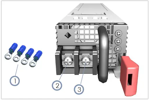
- Use the ring lugs included with the DC PSU.
- DC return
- -48 – -60 VDC
4 Connect Timing Port

RJ-45 Stack-Sync
Use a Cat. 5e or better twisted-pair cable to synchronize devices in master and slave stacking configurations.
RJ-45 PPS/ToD
Use a Cat. 5e or better twisted-pair cable to connect the 1-pulse-per- second (1PPS) and Time of Day to other synchronized devices.
1PPS
Use a coax cable to connect the 1-pulse-per-second (1PPS) to another synchronized device.
5 Make Fabric Connections

400G QSFP-DD Fabric Ports
Install transceivers and then connect fiber optic cabling to the transceiver ports.
The following transceivers are supported in the QSFP-DD ports:
■ QSFP-DD 400GE
■ QSFP56-DD FR4
■ QSFP56-DD DR4
■ QSFP56-DD SR8
Alternatively, connect DAC cables directly to the QSFP-DD slots.
6 Make Network Connections
100G QSFP28 Ports
Install transceivers and then connect fiber optic cabling to the transceiver ports.
The following transceivers are supported in the QSFP28 ports:
■ 100GBASE-CR4
■ 100GBASE-AOC
■ 100GBASE-SR4
■ 100GBASE-PSM4
■ 100GBASE-LR4
■ 100GBASE-CWDM4
■ 100GBASE-ER4
Alternatively, connect DAC cables directly to the QSFP28 slots.
7 Make Management Connections

SFP+ OOBF Ports
Install 10GBASE-SR or 10GBASE-CR transceivers and then connect fiber optic cabling to the transceiver ports.
MGMT RJ-45 Port
Connect Cat. 5e or better twisted-pair cable.
RJ-45 Console Port
Connect the included console cable and then configure the serial connection: 115200 bps, 8 characters, no parity, one stop bit, 8 data bits, and no flow control.
Micro USB Console Port
Connect using a standard USB to Micro USB cable.
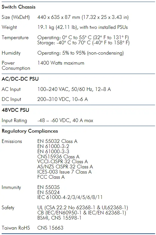
Hardware Specifications
Documents / Resources
 |
Edge-core AS7926-40XKFB 100G Aggregation Router [pdf] User Guide AS7926-40XKFB 100G Aggregation Router, AS7926-40XKFB, 100G Aggregation Router, Aggregation Router, Router |