DWIN Technology DWIN Web Camera Screen
User Guide
Professional, Creditable, Successful
DWIN Web Camera Screen Development Guide
DWIN Technology
1. Product Overview
1.1 Application Introduction
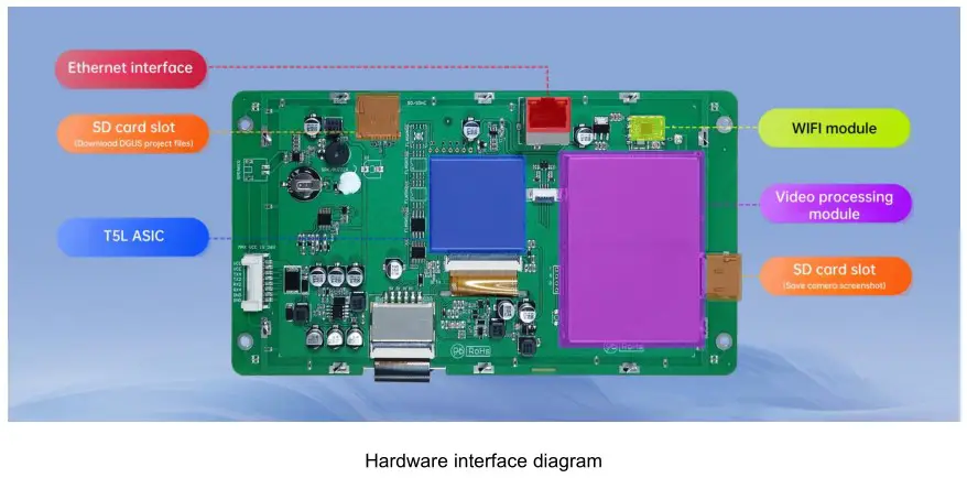
The Dwin DT-series web camera screen incorporates a T5L ASIC as the core control chip, complemented by a video decoding module as a coprocessor. This architecture allows for highly efficient decoding and processing of video signals. Being compatible with high-definition web cameras, the DT series is ideal for HD display applications in diverse industries.
1.2 Product Features
(1) Supports connection to web cameras via Ethernet or Wi-Fi (both 2.4G and 5G bands are available).
(2) Supports web cameras with H.264 encoding under the RTSP protocol.
(3) Supports functions such as full-screen display, picture-in-picture, mirror flip, floating icons, and floating text.
(4) Supports capturing and saving camera screenshots and recording video in MP4 format.
(5) Some models support four channel cameras simultaneous display on the screen.
2. Product Selection
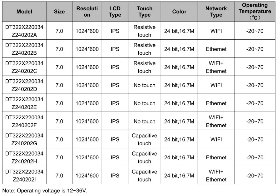
2.1 Dual-channel web camera screen selection table
2.2 Four-channel web camera screen selection table
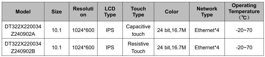
Note: Operating voltage is 9 – 36V. Come with enclosure, and the camera is directly connected to the screen via the Ethernet interface.
3. System Variable Interface Description
Web camera screen can be controlled through the system variable interface (0x0500~0x05BF) reserved by the DGUS system.
3.1 System Variable Interface Definition
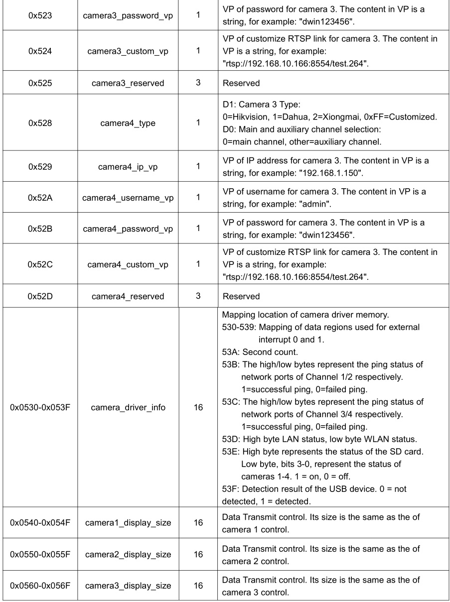
The functions corresponding to the addresses of various system variables used by the web camera are shown in the table below.
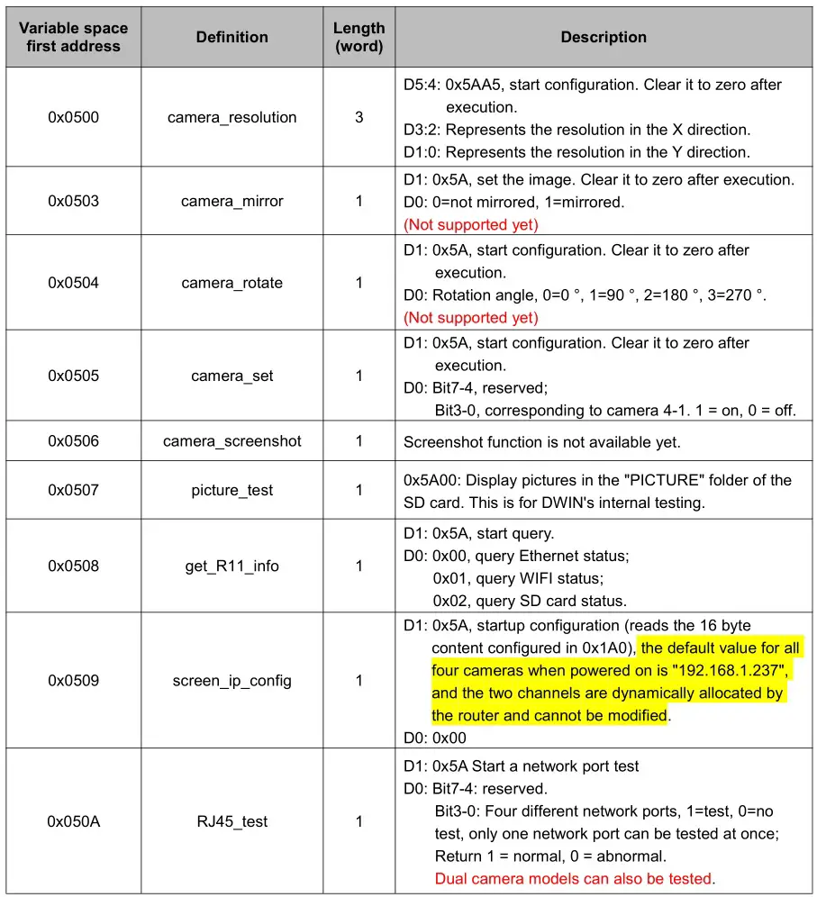
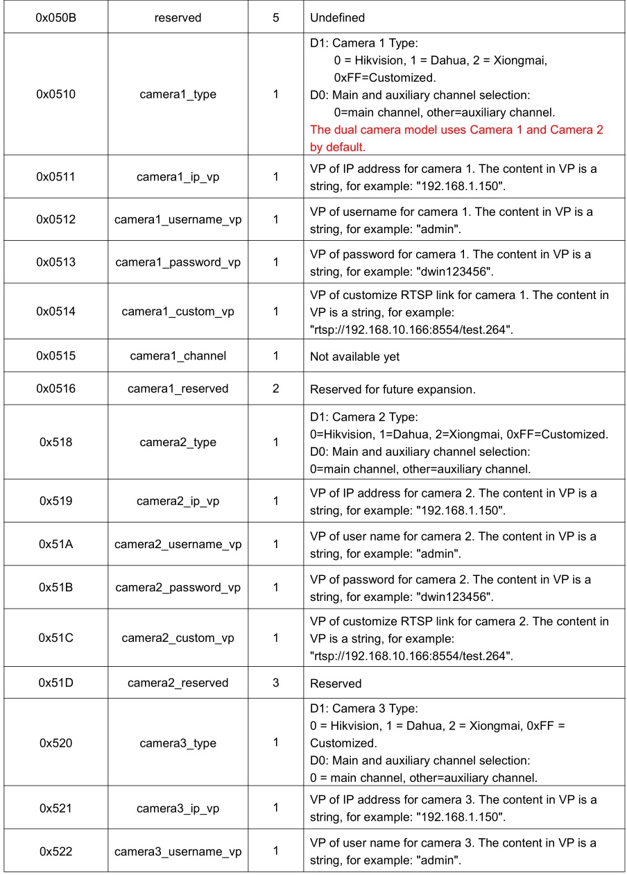

Note: To view saved pictures, it is necessary to close all cameras. Network cameras only require configurations associated with camera 1 and camera 2.
3.2 Application Instance
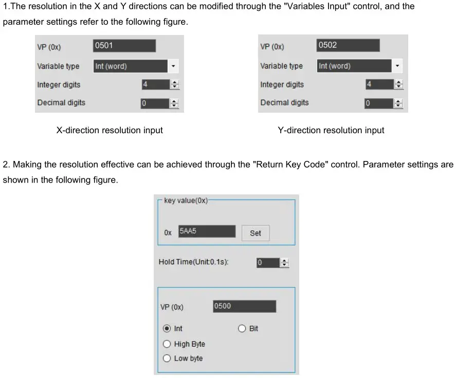
For example, adjusting the resolution through the system variable interface 0x0500 can be achieved by sending commands through the serial port or using DGUS “Return Key Code” control.
(1). Serial port command.
82/83 command: 5AA5 09 82 0500 5AA5 0320 01E0
Command meaning: Frame header Command length 82 (write variable space) System variable address Start resolution processing once Resolution in X and Y direction
Note: After the serial port command is issued, the camera screen will be adjusted to 800 * 480.
(2). DGUS control
4. Camera Interface DGUS Development
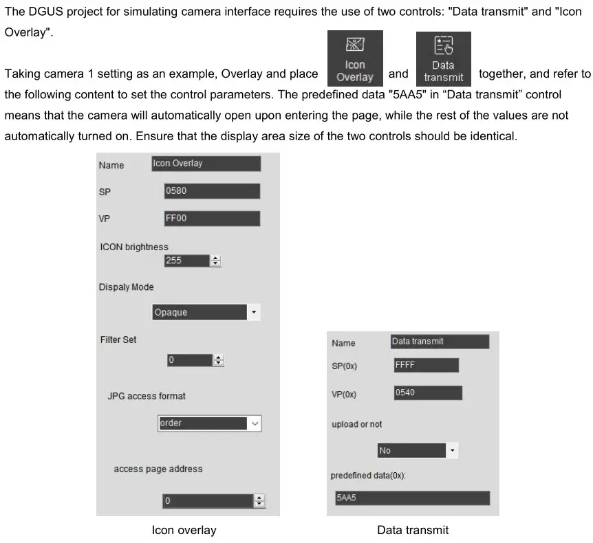
4.1 Camera control settings
4.2 Dynamic adjustment of camera control attributes
Take Camera 1 as an example. The pointer address is 0x0580 (for other cameras, please refer to “3.1 System Variable Interface Definition”). You can dynamically adjust the parameters of the camera control by modifying the content of the corresponding Variable Pointer (VP) address, as detailed in the table below.
Note that before adjusting the camera control attributes, you must turn off the camera!
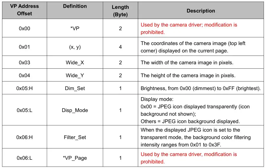
*Note that if you accidentally modify the data in the VP address that is prohibited, you can restore normal operation by restarting the screen.
5. Instructions for Using Web Camera
5.1 View camera IP address
(1) Before obtaining the camera IP, please confirm that the local area network is available. You can verify this by using the ‘ping’ command in the Windows command prompt: win+R, open “Run” enter “cmd” and press enter → enter ‘ping 192.168.1.1’. A successful result, as shown in Figure 5.1, indicates that your local network is working correctly.

(2) As shown in Figure 5.2, for a wired connection, please connect the PC, web camera, and screen to the same LAN through a router. WLAN connection can refer to Part 6 of this guide, “3. How to connect to the WIFI network?”. If the web camera is used for the first time, please register and activate it as instructed by the supplier.

(3) Power the web camera and screen and view the camera IP information through software on the PC. Through the supplier’s supporting software to view the IP address of the camera, such as Hikvision’s SADP, Dahua’s Config Tool and SmartPSS Plus.
Taking Hikvision as an example, the camera IP can be viewed through SADP software (you can find the download webpage by searching for “SADP” on browser).
Open the SADP software and click the “Refresh” button in the upper right corner to view the IP address of the online device (Figure 5.3). If the device cannot be found, please first check if the IP is available. If using WLAN connection, please confirm that the network bandwidth is 2.4G.

Four – channel camera models, this step can be skipped as the screen will automatically configure the IP. You can also manually modify the RTSP address link, ensuring that it is on the same local area network as the screen’s IP (192.168.1.***).
5.2 Screen 22 File Configuration
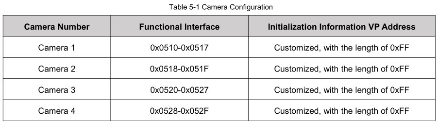
The “22 file” on the network camera screen is configured through the system interface to enable automatic loading of the camera’s IP address, username, password, and custom URLs upon power-on. The camera image won’t display without configuration. The VP addresses associated with the 0x510-0x52F interface are userconfigurable but require a reserved length of 0xFF. This address range is strictly reserved and should not be utilized.
Taking Camera 1 (the 22 file address is A20-A2F) as an example, refer to the following configuration of the 22 file:
0xA20: Camera type (Hikvision in Figure 5.4)
0xA21: Main stream and sub-stream selection
0xA22-0xA23: The starting VP address where the camera IP is stored. The example routine writes 0x1800, see 0x3000 in Figure 5.4.
0xA24-0xA25: The starting VP address where the camera username is stored. The example routine writes 0x1810, see 0x3020 in Figure 5.4.
0xA26-0xA27: The starting VP address where the camera password is stored. The example routine writes 0x1820, see 0x3040 in Figure 5.4.
0xA28-0xA29: The starting VP address where the camera’s customized RTSP address is stored. The example writes 0x1830, see 0x3060 in Figure 5.4.
0xA2A-0xA2F: Reserved and undefined.

Note: For the parameters with the green background marked above, users should fill in according to the actual situation of their own cameras when configuring, and must not fill in by referring to the data in the figure!
5.3 Camera Setting
Taking the Hikvision camera as an example, this section describes how to configure the camera.
(1) Connect the camera, computer, and router, and then log in to the camera by entering the camera’s IP address in the browser to perform settings. The camera needs to be activated for the first login. The default username is “admin”, and the password needs to be set by yourself. Note that the “@” symbol should not be included in the password, otherwise the screen will not be able to connect to the camera!

(2) Main stream settings
As shown in Figure 5.6, after logging in, click on “Audio/Video” to configure the following items. Click “Save” after completion.
Video Type: Video Stream.
Resolution: 720P and below.
Video Encoding: H.264.

(3) Sub-stream settings
The sub-stream is set with reference to the content in Figure 5.7. Click “Save” after completion.

(4) The configuration of Dahua cameras can refer to Figure 5.8.

(5) Dual-channel/Four-channel simultaneous display settings
It is recommended to turn off the audio input to avoid issues with the camera image display..
5.4 Camera Image Display
Download the configured 22 file to the screen via the SD card, connect the camera, screen, and router. After the system is powered on and you hear a “beep” from the screen, click the camera icon on the main page to enter the camera display page. Click “ON” to display the image captured by the network camera (as shown in Figure 5.9).

5.5 Camera Custom Link
The camera type can be manually clicked to select. When “Custom” is selected, the screen will use the camera corresponding to the custom link.

6. Common Questions
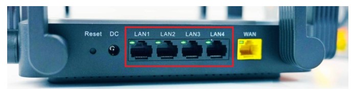
1. Unable to display camera screen after connecting to router?
Check if the network cable connection is correct and be careful not to use the WAN interface (the interface shown in the red box in the figure below can be used). Note that the four-channel network camera screen does not need a router.
2. Is it possible to use the web camera without a router?
Yes, you can connect the web camera directly to the screen. However, in this case, you need to download special single-channel display firmware.
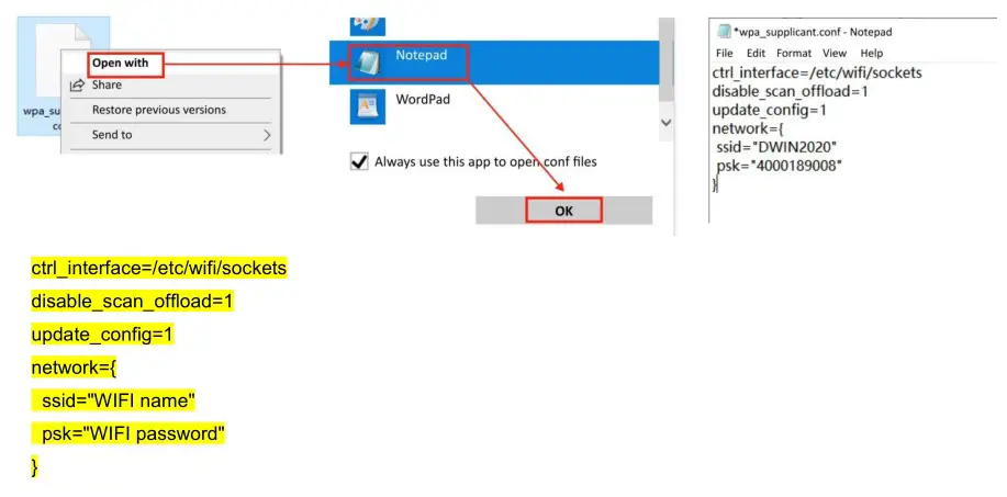
3. How to connect to the WIFI network?
Method 1: Use Notepad to open the “wpa_supplicant. conf” file on the USB disk, fill in your written WIFI name (SSID) and password in the following format, save the file, and make sure to place it in the root directory of the USB disk. After the screen is powered on, the file parameters will be automatically read and WIFI configuration will be performed.
4. The project settings and the parameter are correct, but the camera image cannot be displayed?
When using the web camera, you need to ensure that the screen and the web camera are on the same local area network, otherwise the image may not be displayed. You can follow the steps below to confirm whether the network segments of the camera and the screen are the same:
(1) As shown in the red box in Figure 1, use a serial port adapter to connect the Tx, Rx, and GND serial ports near the functional module, so that the screen can communicate with the computer.

(2) Screen connection to the local area network
For wired connection, directly connect the screen and the router with network cable. For wireless connection, please refer to “3. How to connect to the WIFI network?”.
(3) Querying the screen’s IP address
Open the serial port tool MobaXterm, select the correct serial port number as shown in Figure 2, and set the baud rate to 921600. After configuration, click OK, press “Enter”, and the screen shown in Figure 3 will be displayed.

(4) Type “ifconfig -a” and press “Enter” to view the device’s IP. Among them, eth0 is for wired connection, and wlan0 is for wireless connection. The presence of “inet addr” indicates that the network connection is normal.

(5) Confirm the camera’s IP and whether the screen and the camera are on the same network. Enter the command “ping 192.168.1.64” and press “Enter”. The pink-colored part in the displayed content is the camera’s IP. As shown in Figure 5, it indicates that the connection with the camera is successful. To exit the ping operation, just press Ctrl + C.

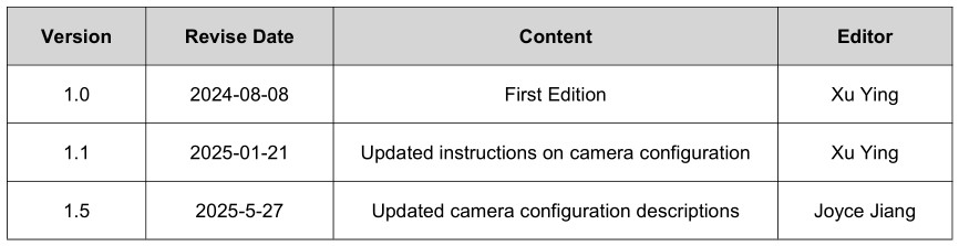
7. Revision Records
Please contact us if you have any questions about the use of this document or our products, or if you would like to know the latest information about our products:
- Customer service Tel: +86 400 018 9008
- Customer service email: dwinhmi@dwin.com.cn
- DWIN Developer Forum: https://forums.dwin-global.com/
Thank you all for continuous support of DWIN,and your approval is the driving force of our progress!
DWIN Technology
Documents / Resources
 |
DWIN Technology DWIN Web Camera Screen [pdf] User Guide DMT80600C080_01W, DMT80600C080 DWIN Web Camera Screen, DMT80600C080, DWIN Web Camera Screen, Web Camera Screen, Camera Screen |