DOEPFER A-180-9 Multicore Module Idea

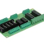
Position and function of the connectors
(available from version 2)
From version 2 four additional pin headers are available to enable internal default connections of two modules:
- JP1A : outputs 1-8
- JP1B : inputs 1-8
- JP2A : outputs A-F
- JP2B : inputs A-F
That way the signals of module #1 can be forwarded internally to module #2 (e.g. the master clock signal even to a third case by means of four module A-180-9). The default inputs (JP1B, JP2B) are internally wired to the switching contacts of the module sockets. That way the default connections can be interrupted by plugging a cable into the corresponding socket.
Dual row female IDC connectors for ribbon cables with 8 pins and 2 mm pitch are required to establish the connections between to modules:
- JP1A module #1 (outputs 1-8 module #1) JP1B module #2 (inputs 1-8 module #2)
- JP2A module #1 (outputs A-F module #1) JP2B module #2 (inputs A-F module #2)
Pay attention to the correct alignment of the ribbon cables (colored stripe = dot mark on the pc board).
Documents / Resources
 |
DOEPFER A-180-9 Multicore Module Idea [pdf] Instructions A-180-9, Multicore Module Idea, Module Idea, Multicore Idea, Multicore, A-180-9 |