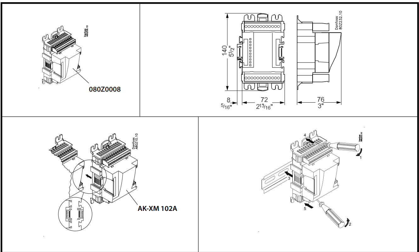
Danfoss XM 102A Extension Module

Product details
| Gross weight | 0.354 Kilogram |
| Net weight | 0.2 Kilogram |
| Volume | 2.554 Liter |
| EAN | 5702428078832 |
| Application area | Additional In- and Outputs |
| Approval | C-TICK CE LLC CDC TYSK UR |
| CE evaluated | Yes |
| Communication type | AK2 LOCAL BUS |
| Controller type | Extension Module |
| Customer part number | 00P305 |
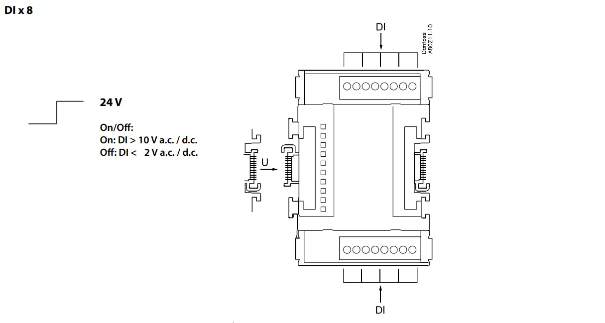
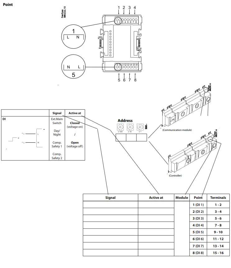
| Digital inputs (DI) [pc] | 8 pc |
| Display on front | No |
| Division | 25 |
| EEE category | 5 small equipment (any external dimension < 50 cm) |
| Equipment | Standard blocks |
| EU RoHS compliance | Out of scope |
| Function | Digital Inputs |
| Further information | Low voltage |
| In scope of WEEE | Yes |
| Packing format | Multi pack |
| PFAS content [Yes/No] | No |
| Power consumption [VA] | 1 VA |
| Product accessories | Electron. control accessories |
| Product group | I/O and communication modules |
| Product Name Description | I/O module |
| Quantity per packing format | 16 pc |
| REACH Candidate List substances | No |
| Serviceable | No |
| Type | AK-XM 102A |
Design
Menu list. This menu function can be used together with the system software type AKM. The description is divided up into function groups that can be displayed on the PC screen. Within each group, it is now possible to show the measured values or settings. Regarding the use of AKM, reference is made to the AKM Manual.
Validity
This menu operation (from September 2012) applies to controller type AK-LM 330, code Nos 080z0170 with programme version 1.4x.
Function groups
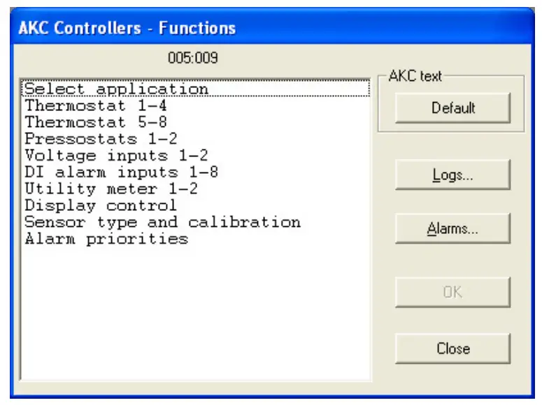
The operation is divided up into several functional groups. When a selection has been made, push “OK”, and you may continue to the next display. By way of example, “Thermostat 1-4” has been selected here. From the measuring line the different values can be read. The values are constantly updated. In the list of settings, the set values can be seen. If a setting has to be changed, select the parameter and proceed via “OK”.

Measurements
The various measurements can be read directly. If a graphic display of the measurements is required, up to eight of them can be shown. Select the required measurements and push “Trend”.
Settings
Settings can only be made for the daily operation. Configuration settings cannot be seen, changed or written out. They can only be made from the Service Tool programme. There are four kinds of settings: ON/OFF settings, settings with a variable value, time settings and “reset alarms”.
Go through the individual functions one by one and make the required settings. When settings have been made for one controller, the set values may be used as a basis in the other controllers of the same type and with the same software version. Copy the settings by using the copy settings function in the AKM programme, and subsequently adjust any settings where there are deviations. NB! If a list is required for noting down the individual settings, a printout can be made of it with a function in the AKM programme. Read the next section, “Documentation”.
Documentation
Documentation of the settings of the individual controllers can be made with the print function in the AKM programme. Select the controller for which documentation of the settings is required and select the “Print Settings” function (cf. also the AKM Manual).
Functions
Shown below are function groups with corresponding measurements and settings. A printout of the given settings can be made using the AKM function “Print Settings” (see above).
Note It has been necessary to make a selection from the numerous measurements and settings coming from the controller. There is not room for all these in the AKM programme controls.
It can display:
- 8 thermostats
- 2 pressostats
- 2 volt inputs
- 8 digital alarm inputs
- 2 consumption gauges
If it is necessary to obtain access to all measurements and settings, see Using Service Tool, type AK-ST 500.
Select application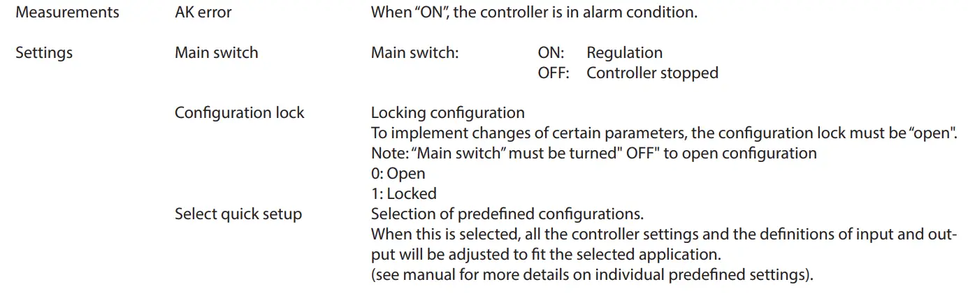
Thermostat 1 – 4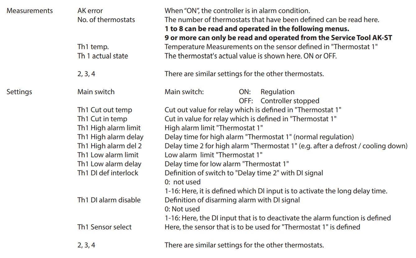
Thermostat 5 – 8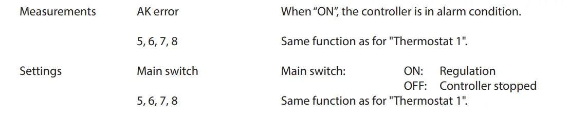
Pressostats 1 – 2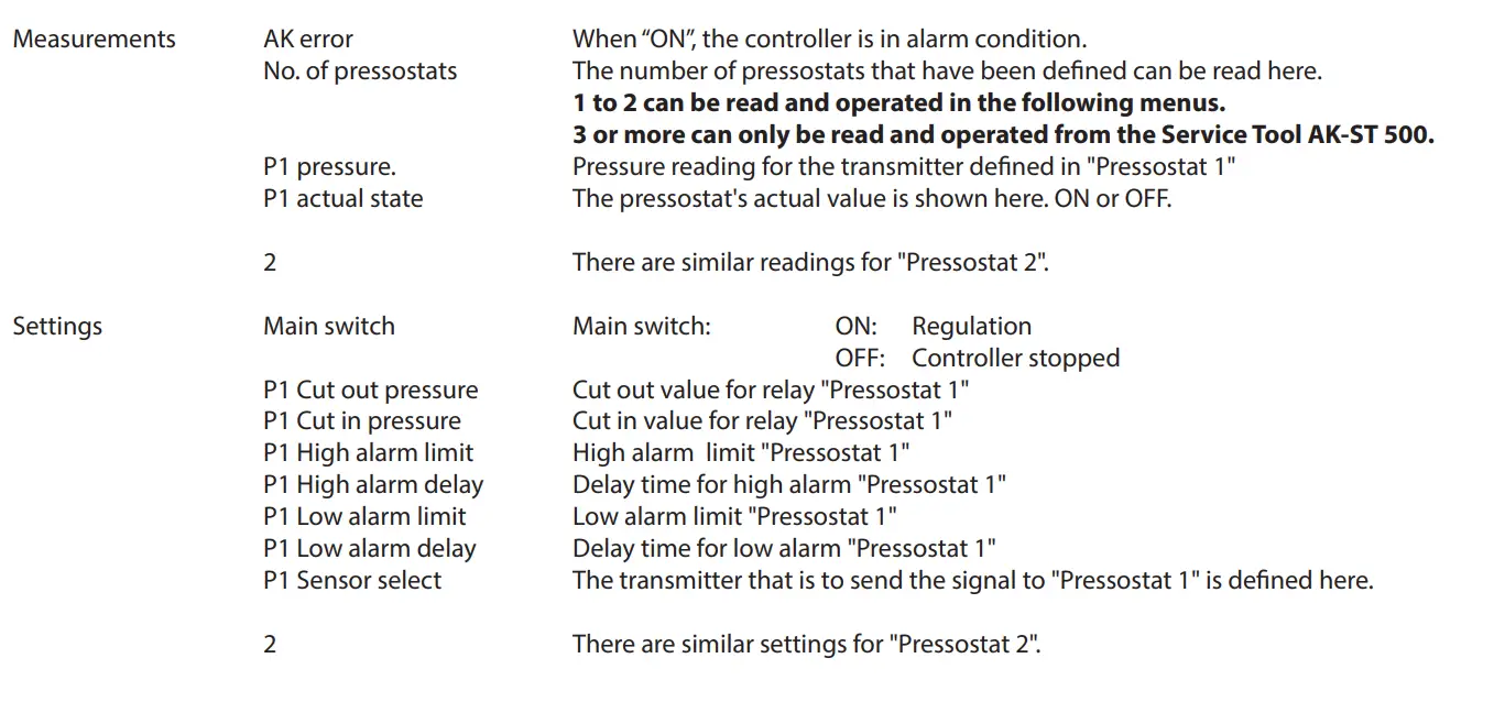
Voltage inputs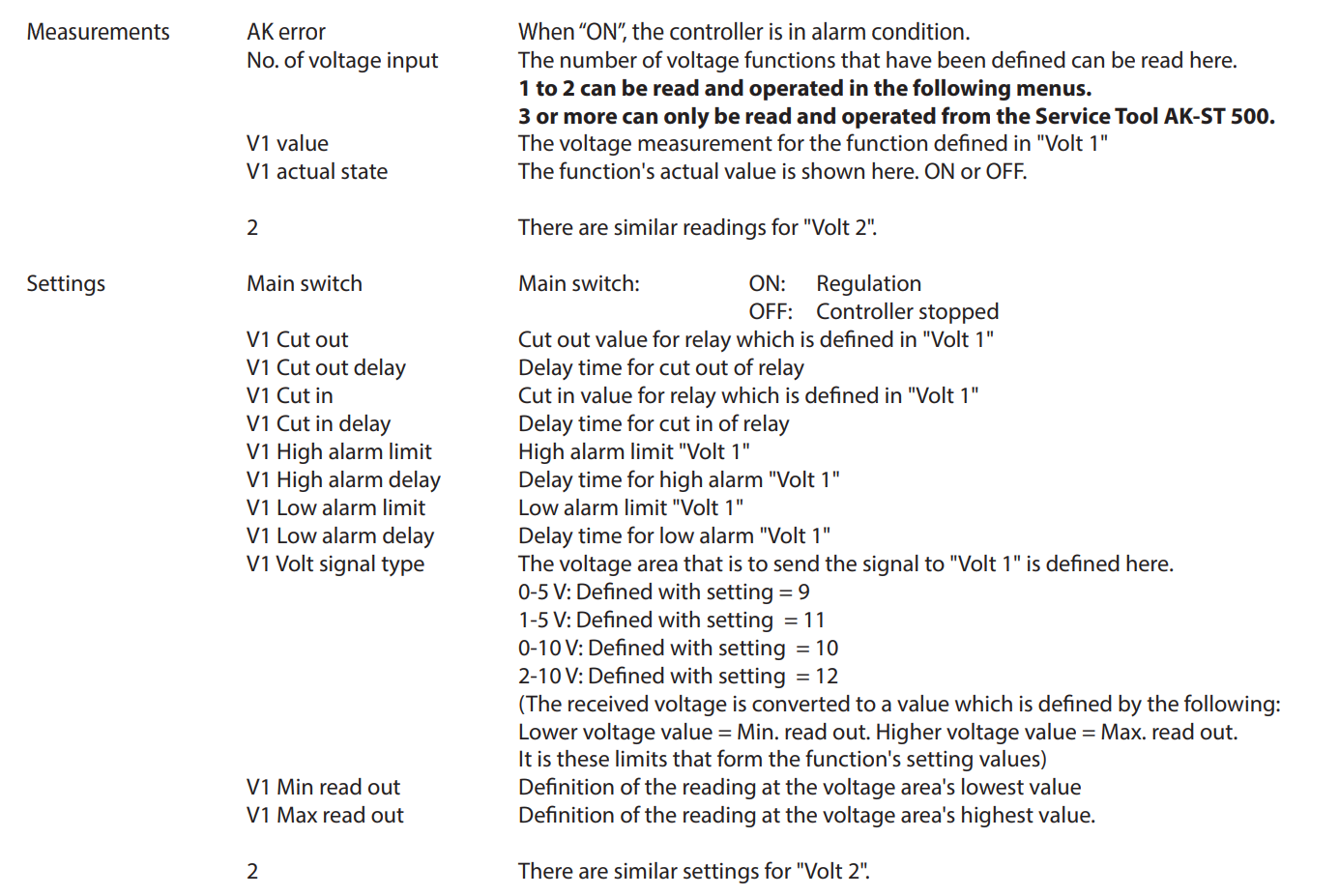
DI alarm inputs 1-8
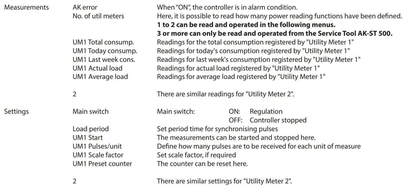
Utility meter 1-2
Display control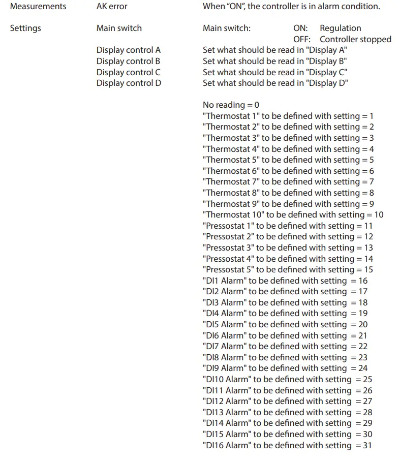
Sensor type and calibration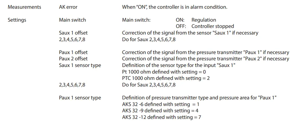
- AKS 32 -20 defined with setting = 10
- AKS 32 -34 defined with setting = 13
- AKS 32 -50 defined with setting = 16
- AKS 32R -6 defined with setting = 2
- AKS 32R -9 defined with setting = 5
- AKS 32R -12 defined with setting = 8
- AKS 32R -20 defined with setting = 11
- AKS 32R -34 defined with setting = 14
- AKS 32R – 50 defined with setting = 17
- AKS 2050 -59 defined with setting = 31
- AKS 2050 -99 defined with setting = 32
- AKS 2050 -159 defined with setting = 33
- User-defined defined with setting = 0. + settings via Service Tool.
2 Do for Paux 2.
Alarm priorities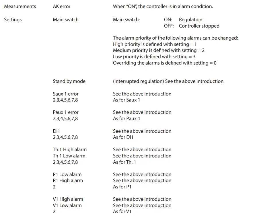
Danfoss can accept no responsibility for possible errors in catalogues, brochures and other printed material. Danfoss reserves the right to alter its products without notice. This also applies to products already on order, provided that such alterations can be made without subsequent changes being necessary in specifications already agreed. All trademarks in this material are property of the respective companies. Danfoss and Danfoss logotype are trademarks of Danfoss A/S. All rights reserved.
Installation
The Product contains electrical components And may not be disposed together with domestic waste. Equipment must be separate collected with Electrical and Electronic waste. According to Local and currently valid legislation.
Frequently Asked Questions
- Q: How should I dispose of the product?
- A: The Product contains electrical components and should not be disposed of with domestic waste. It must be separately collected with Electrical and Electronic waste according to local and currently valid legislation.
Documents / Resources
 |
Danfoss XM 102A Extension Module [pdf] Instructions 080Z0008, RI8HG502, XM 102A Extension Module, Extension Module, Module |