![]() TOMORROW
TOMORROW
Operating Guide
Functional Extensions
iC7 Series
 drives.danfoss.com
Introduction
1.1 Purpose of the Operating Guide
This operating guide provides information for safe installation, commissioning, and operation of functional extensions used with iC7 drives.
This guide is intended for use by qualified personnel only. Read and follow the operating instructions to use the drive safely and professionally, and pay particular attention to the safety instructions and general warnings. Keep this operating guide available with the drive at all times.
1.2 Additional Resources
- Additional resources are available to help understand the features, and safely install and operate the iC7 products:
- Safety guides, which provide important safety information related to installing iC7 drives.
- Installation guides, which cover the mechanical and electrical installation of drives, or functional extension options.
- Design guides, which provide technical information to understand the capabilities of the iC7 drives for integration into motor control and monitoring systems.
- Application guides, which provide instructions on setting up the drive for a specific end use.
- Supplemental publications, drawings, and manuals are available at www.danfoss.com.
Latest versions of Danfoss product manuals are available for download at http://drives.danfoss.com/downloads/portal/.
1.3 Version History
This guide is regularly reviewed and updated. All suggestions for improvement are welcome.
The original language of this guide is English.
Table 1: Version History
| Version | Remarks |
| AQ390830267692, version 0501 | Information on configuring Relay Option OC7R0 added. |
| AQ390830267692, version 0401 | Information on support for SinCos encoders added. |
| AQ390830267692, version 0301 | Updates regarding electrical specifications, and the default value and available selections of parameter 9.6.6 BiSS/SSI Clock Rate. |
| AQ390830267692, version 0201 | Updates regarding Encoder/Resolver Option OC7M0 features. |
| AQ390830267692, version 0101 | First version. The information in this version is valid for Encoder/Resolver Option OC7M0 installed in iC7-Automation frequency converters. |
Safety
2.1 Safety Symbols
The following symbols are used in this guide:
![]() DANGER
DANGER ![]()
Indicates a hazardous situation which, if not avoided, will result in death or serious injury.
![]() WARNING
WARNING ![]()
Indicates a hazardous situation which, if not avoided, could result in death or serious injury.
![]() CAUTION
CAUTION ![]()
Indicates a hazardous situation which, if not avoided, could result in minor or moderate injury.
NOTICE
Indicates information considered important, but not hazard-related (for example, messages relating to property damage).
2.2 Safety and Installation Awareness
Before starting installation, read all safety guidelines and precautions related to installing functional extensions.
For more information on functional extension selection and functional extension slots in the drives, see the product-specific design guides. Supplemental information and other iC7 guides can be downloaded from www.danfoss.com/service-and-support.
Configuration
3.1 Configuration Overview
The parameters related to functional extensions are in parameter group 9, called I/O. Parameters are dependent on the mounting, and will appear in the parameter menu after the functional extension has been mounted and wired.
Installation
4.1 Checking the Shipment
Make sure that the items supplied and the information on the product label correspond to the order confirmation. The product label is placed on the front and right side of the option casing.
 Illustration 1: Example of a Product Label
- Product name of the functional extension
- Code number
- Serial number
- A 2D code which contains the code number, serial number, production year and week, and the product name.
- Identification of I/O connections on the option
- Compliance and approval markings (if not covered by drive approvals).
4.2 Installing Functional Extensions in Frequency Converters
The instructions in this chapter apply to frequency converters with an integrated control board.
![]() DANGER
DANGER ![]()
SHOCK HAZARD FROM THE AC DRIVE
Touching electrical parts of the drive can cause death or serious injury even after the equipment has been disconnected from AC power.
Perform the following steps before touching any internal components:
Disconnect the mains power.
Disconnect the motor.
Disconnect external connections to the DC terminals of the drive.
Wait for the capacitors to discharge fully. Refer to the label on the drive for the correct discharge time.
Ensure that the DC-link capacitors have discharged fully by measuring the DC link with a voltage meter.
NOTICE
The Encoder/Resolver Option OC7M0 must be installed in option slot A.
– For more information on option slot locations in frequency converters, refer to the design guide.
– For information on slot identification in software, refer to the application guide.
- Remove the control panel, terminal cover, and control panel cradle.
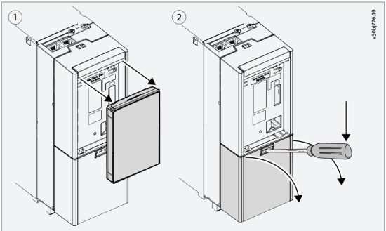
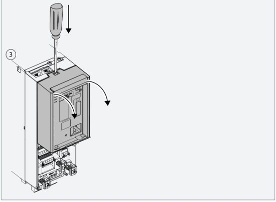
- Remove the interface board, place the option board in the slot, and reinstall the interface board.


4.3 Installing Boards to the Modular Control Unit
Use these instructions to install a board, for example an option board, to the mounting plate of the modular control unit.
![]() CAUTION
CAUTION![]()
DAMAGE TO OPTION BOARDS
Do not install, remove, or replace option boards on the drive when the power is on. Doing this can cause damage to the boards.
– Switch off the AC drive before installing, removing, or replacing option boards on the drive.
Procedure
- Remove the screw that is pre-attached to the fixing point at the top of the mounting plate and keep it.
- Slide the lower edge of the board to the mounting plate fixing point.
 Illustration 2: Installing a Board to the Modular Control Unit Mounting Plate
1. Option connector
2. Option board
3. Fixing point at the top4. Fixing point at the middle
5. Fixing point at the bottom - Use the screw to attach the board to the fixing point at the top.
- Attach an option connector to the newly installed board and the board next to it.
Encoder/Resolver Installation and Configuration
5.1 Encoder/Resolver Option OC7M0
The Encoder/Resolver option supports connecting various devices as speed/position feedback or reference. It also has a TTL encoder simulation output, which can be used to mirror the resolver input signal.
There are 4 channels (A, B, Z, and D) which can be configured in different combinations according to Table 2.
Table 2: Encoder/Resolver Option Configurations
| Device | Tracks |
| Incremental TTL/HTL | A and B |
| Incremental TTL/HTL with zero pulse | A, B, and Z |
| Resolver | A and B |
| Resolver with encoder mirror out | A and B + Z and D |
| SinCos | A and B |
| SSI | Z and D |
| EnDat | Z and D |
| BiSS | Z and D |
| HIPERFACE DSL | D |
Adjustable encoder voltage supply is available 5–24 V with the possibility of feedback enabling monitoring and compensation for cable voltage drop. The voltage level is set with parameter 9.4.4 Encoder supply voltage.
NOTICE
Setting the voltage too high can damage the connected encoder.
Resolver supply/excitation is available with adjustable voltage and frequency by parameters 9.7.1 Excitation Voltage and 9.7.2 Excitation Frequency.
5.2 Required Tools
- Torx 20 screwdriver for mounting EMC plate Slot C-E.
- Slotted screwdriver (maximum 3 mm) for releasing the spring-loaded terminals of the plug connector.
- Wire crimpers may be needed for certain encoder cable types.
5.3 Items Supplied
The Encoder/Resolver OC7M0 option can be ordered as a preinstalled option by using the dedicated model code, or as a separate option for field mounting by using the code number.
When the option is not mounted at the factory, the following items are included in the shipment:
- Encoder/Resolver OC7M0.
- Option connector.
- Cable clamps.
- Screws.
- Operating guide.
5.4 Pin Assignment for Encoder/Resolver OC7M0
The Plug detect feature, which monitors that pins 11 and 13 are connected, detects the unintentional disconnection of the plug connector.
NOTICE
If the Plug detect connection is missing while the interface is activated (parameter 9.4.1 Interface configuration ≠ “Disabled”), the drive generates a fault.
– The fault is generated only when switching to closed-loop operation, not when selecting an encoder.
– The plug connector is delivered without a connection between pin 11 and 13.
Table 3: Pin Assignment and Function for Encoder/Resolver Option OC7M0
| Numbering | Functions | Numbering | Functions |
| 1 | Resolver Excitation – | 2 | Resolver Excitation + |
| 3 | GND | 4 | Ch. D- (TTL, RS-485, HIPERFACE DSL®) |
| 5 | GND | 6 | Ch. D+ (TTL, RS-485, HIPERFACE DSL®) |
| 7 | Encoder Supply Sensor – | 8 | Ch. Z- (TTL, HTL, RS-485, R-) |
| 9 | Encoder Supply Sensor + | 10 | Ch. Z+ (TTL, HTL, RS-485, R+) |
| 11 | Plug Detect – (GND) | 12 | Ch. B- (TTL, HTL, RS-485, Analog B-) |
| 13 | Plug Detect + | 14 | Ch. B+ (TTL, HTL, RS-485, Analog B+) |
| 15 | Encoder Supply – (GND) | 16 | Ch. A- (TTL, HTL, RS-485, Analog A-) |
| 17 | Encoder Supply + | 18 | Ch. A+ (TTL, HTL, RS-485, Analog A+) |
5.5 Encoder/Resolver Option OC7M0 Specifications
NOTICE
Voltage can be up to 24 V. Setting the voltage too high can damage the connected encoder.
The voltage is configured in parameter 9.4.4 Encoder Supply Voltage. For details, refer to 5.7.1 Configuration (Menu Index 9.4).
Table 4: Electrical Specifications for Encoder/Resolver Option OC7M0
| Encoder supply voltage [V DC] | Maximum current [mA] |
| 24 | 125 |
| 15 | 150 |
| 12 | 150 |
| 8 | 225 |
| 5 | 300 |
If the available power is insufficient, it is possible to use an external power supply for the encoder.
Table 5: Device Type Specifications
| Device type | Specifications | Additionalinformation11l | ||
| Data | Value | |||
| TTL (A, B, Z) | Signal level | 0–5 V | Differential signals are preferred, but single signals are also supported. The trigger threshold is 0.33–0.4 times the encoder supply voltage. | |
| Maximum resolution | 65535 | |||
| Maximum frequency | 750 kHz | |||
| Maximum cable length | Depends on sig- nalfrequency | |||
| HTL (A, B, Z) | Signal level | 0-24 v | ||
| Maximum resolution | 65535 | |||
| Maximum frequency | 500 kHz | |||
| SinCos | Signal level | 1 V peak-peak | – | |
| Maximum resolution | 65535 | |||
| Maximum frequency | 750 kHz | |||
| SSI | Maximum resolution | 31 bit | – | |
| Maximum data length | 63 bit | |||
| Maximum clock frequency | 2 MHz | |||
| EnOat | Maximum resolution | 31 bit | Both EnDat 2.1 and EnDat 2.2 are supported, but only with pure absolute channel, not with incremental channel. | |
| Maximum data length | 63 bit | |||
| Maximum clock frequency | 8.33 MHz | |||
| HIPERFACE DSL | Maximum resolution | 31 bit | Baud rate is fixed. | |
| Maximum data length | 63 bit | |||
| Baud rate | 10 Mbps | |||
| BiSS | Maximum resolution | 31 bit | – | |
| Maximum data length | 63 bit | |||
| Maximum clock frequency | 8.33 MHz | |||
| Resolver | Excitation voltage | 2–8 Vrms | ||
| Excitation frequency | 2–20 kHz | |||
| Maximum number of poles | 254 | |||
| Maximum input voltage | 8 Vrms | |||
| Maximum load | 100 mArms | |||
| Encoder simulation (TTL Output) | Voltage level | Minimum: 1.5 V Typical: 2 V differential |
||
| Maximum resolution | 65535 | |||
| Maximum frequency | 750 kHz | |||
| Maximum load | 60 mA | |||
1 The limitations described in this guide apply to the current software version.
Table 6: Cable Specifications for Encoder/Resolver Option OC7M0
| Cable type | Cross-section [mm2 (AWG)] | Minimum stripping length [mm (in)] |
| Flexible/rigid wire without cable end sleeves | 0.2–1.5 (26–16) | 10 (0.4) |
| Flexible wire with cable end sleeves with collar | 0.2–0.75 (26–18) |
A standard RS485 interface supports cable lengths up to 1200 m (3940 ft) depending on signal frequency and cable type. Consult the documentation for the respective encoder or resolver for details on allowed cable length.
5.6 Setup and Connection Examples for Encoder/Resolver OC7M0
5.6.1 Incremental Encoder
With TTL and HTL incremental encoder, the actual position is 0 after power-up, and encoder pulses are counted to increment or decrement the actual position. For improved resolution with TTL and HTL encoders, both the positive and negative edge of A and B pulses are detected giving 4 quad counts per encoder pulse.
Table 7: Parameters for Incremental Encoder
| Parameter | Setting |
| 9.4.1 Interface configuration | Set according to the type of connected encoder. TTL/HTL with 2 tracks: Select [1] 2 track Incremental A, B. TTL/HTL with 3 tracks: Select [3] 3 track Incremental A, B, Z. |
| 9.4.4 Encoder Supply Voltage | Set the appropriate supply voltage for the connected encoder. NOTICE Voltage can be up to 24 V. Setting the voltage too high can damage the connected encoder. |
| 9.5.1 Resolution Device 1 | Set the resolution of the encoder in pulses per revolution. |
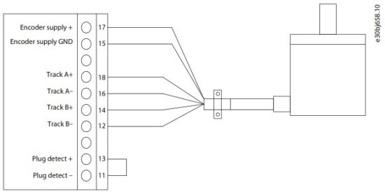
Illustration 3: Wiring Configuration for Incremental Encoder, 2 Differential Tracks (TTL, HTL)
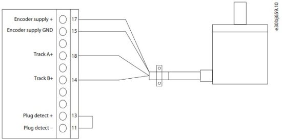 Illustration 4: Wiring Configuration for Incremental Encoder, 2 Single Tracks (TTL, HTL)
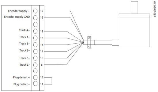 Illustration 5: Wiring Configuration for Incremental Encoder, 3 Differential Tracks (TTL, HTL)
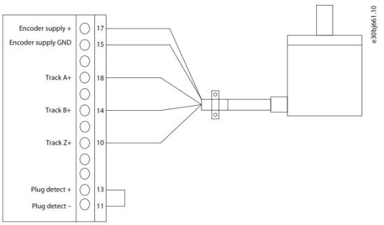 Illustration 6: Wiring Configuration for Incremental Encoder, 3 Single Tracks (TTL, HTL)
5.6.2 Two Incremental Encoders
It is possible to connect two 2-track incremental encoders where channel 1 (A, B) supports TTL and HTL, while channel 2 (Z, D) only supports TTL.
Table 8: Parameters for 2 Incremental Encoders
| Parameter | Setting |
| 9.4.1 Interface configuration | Select [5] 2 track Incremental A,B + 2 track incremental Z,D. |
| 9.4.4 Encoder Supply Voltage | Set the appropriate supply voltage for the connected encoders. If the power requirement exceeds the maximum power of the internal supply, the 2 nd encoder may require external supply. NOTICE Voltage can be up to 24 V. Setting the voltage too high can damage the connected encoder. |
| 9.5.1 Resolution Device 1 | Set the resolution of the encoder connected to A and B in pulses per revolution. |
| 9.5.2 Resolution Device 2 | Set the resolution of the encoder connected to Z and D in pulses per revolution. |
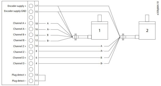
Illustration 7: Wiring Configuration for 2 Incremental Encoders
- Incremental encoder, 2 differential tracks (TTL, HTL)
- Incremental encoder, 2 differential tracks (only TTL on Z and D).
NOTICE
The incremental encoder connected to channels Z and D may require separate supply.
5.6.3 Resolver
With a resolver, the actual position is set to the absolute value within 1 resolver pole pair based on the analog value of the sine and cosine signals.
With a 2-pole resolver, this corresponds to the absolute position within 1 resolver revolution.
Table 9: Parameters for Resolver
| Parameter | Setting |
| 9.4.1 Interface configuration | Set to [7] Resolver A,B. |
| 9.7.1 Excitation Voltage | Set the excitation voltage according to the specification of the connected resolver. |
| 9.7.2 Excitation Frequency | Set the excitation frequency according to the specification of the connected resolver. |
| 9.7.3 Number of Poles | Set the number of poles of the connected resolver. |
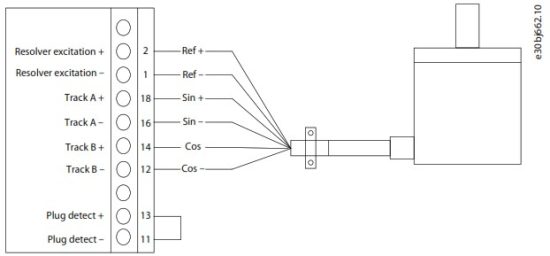
Illustration 8: Wiring Configuration for Resolver
5.6.4 Resolver with Mirror Out
When using a resolver, a TTL encoder signal can be generated to mirror the resolver signal. The mirroring enables transferring the shaft position to other devices for monitoring, or further control. The encoder output signal can be scaled by defining the number of pulses representing 1 rotation of the resolver.
Table 10: Parameters for Resolver with Mirror Out
| Parameter | Setting |
| 9.4.1 Interface Configuration | Set to [8] Resolver A,B + Mirror out Z,D. |
| 9.5.2 Resolution Channel 2 | Set the required number of pulses for the encoder output representing 1 rotation of the resolver. |
| 9.7.1 Excitation Voltage | Set the excitation voltage according to the specification of the connected resolver. |
| 9.7.2 Excitation Frequency | Set the excitation frequency according to the specification of the connected resolver. |
| 9.7.3 Number of Poles | Set the number of poles of the connected resolver. |
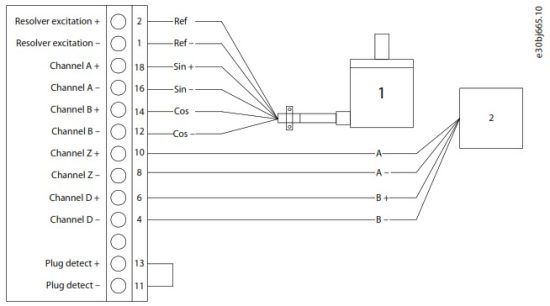
Illustration 9: Wiring Configuration for Resolver with Mirror Out
- Resolver
- Controller, or other device
5.6.5 SinCos Encoder
Table 11: Parameters for SinCos Encoder
| Parameter | Setting |
| 9.4.1 Interface configuration | Select [10] SinCos A,B. |
| 9.4.4 Encoder Supply Voltage | Set the appropriate supply voltage for the connected encoder. NOTICE Voltage can be up to 24 V. Setting the voltage too high can damage the connected encoder. |
| 9.5.1 Resolution Device 1 | Set the resolution of the encoder in pulses per revolution. |
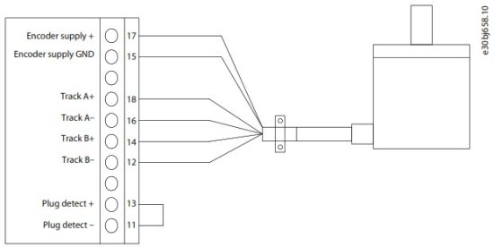
Illustration 10: Wiring Configuration for SinCos Encoder
5.6.6 SSI Encoder
Absolute position is read from the encoder and used to set the actual position after power-up.
Table 12: Parameters for SSI Encoder
| Parameter | Setting |
| 9.4.1 Interface Configuration | Select [17] SSI Z,D. |
| 9.4.4 Encoder Supply Voltage | Set the appropriate supply voltage for the connected encoder. NOTICE Voltage can be up to 24 V. Setting the voltage too high can damage the connected encoder. |
| 9.6.1 Singleturn Resolution | Set the number of bits used for 1 revolution. |
| 9.6.2 Multiturn Resolution | Set the number of bits used for revolution count. |
| 9.6.6 BiSS/SSI Clock Rate | Set the clock rate used for SSI or BiSS. |
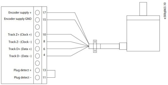
Illustration 11: Wiring Configuration for 2-Track SSI Encoder
5.6.7 EnDat Encoder
Absolute position is read from the encoder and used to set the actual position after power-up.
Table 13: Parameters for EnDat Encoder
| Parameter | Setting |
| 9.4.1 Interface configuration | Select [22] EnDat Z,D. |
| 9.4.4 Encoder Supply Voltage | Set the appropriate supply voltage for the connected encoder. NOTICE Voltage can be up to 24 V. Setting the voltage too high can damage the connected encoder. |
| 9.6.1 Singleturn Resolution | Set the number of bits used for 1 revolution. |
| 9.6.2 Multiturn Resolution | Set the number of bits used for revolution count. |
| 9.6.3 EnDat Clock Rate | Set the rate for the clock signal according to the encoder specifications. |
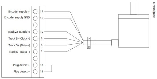
Illustration 12: Wiring Configuration for 2-Track EnDat Encoder
5.6.8 BiSS Encoder
Absolute position is read from the encoder and used to set the actual position after power-up.
Table 14: Parameters for BiSS Encoder
| Parameter | Setting |
| 9.4.1 Interface configuration | Select [29] BiSS Z,D. |
| 9.4.4 Encoder Supply Voltage | Set the appropriate supply voltage for the connected encoder. NOTICE Voltage can be up to 24 V. Setting the voltage too high can damage the connected encoder. |
| 9.6.1 Singleturn Resolution | Set the number of bits used for 1 revolution. |
| 9.6.2 Multiturn Resolution | Set the number of bits used for revolution count. |
| 9.6.6 BiSS/SSI Clock Rate | Set the rate for the clock signal according to the encoder specifications. |
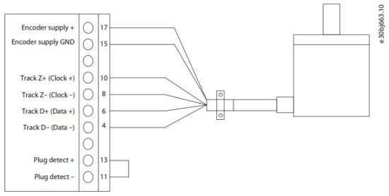
Illustration 13: Wiring Configuration for 2-Track BiSS Encoder
5.6.9 HIPERFACE DSL
Absolute position is read from the encoder and used to set the actual position after power-up.
Table 15: Parameters for HIPERFACE DSL
| Parameter | Setting |
| 9.4.1 Interface configuration | Select [26] Hiperface DSL D. |
| 9.4.4 Encoder Supply Voltage | Set the appropriate supply voltage for the connected encoder. NOTICE Voltage can be up to 24 V. Setting the voltage too high can damage the connected encoder. |
| 9.6.1 Singleturn Resolution | Set the number of bits used for 1 revolution. |
| 9.6.2 Multiturn Resolution | Set the number of bits used for revolution count. |
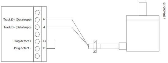
Illustration 14: Wiring Configuration for HIPERFACE DSL Encoder
5.7 Parameter Descriptions for Encoder/Resolver
5.7.1 Configuration (Menu Index 9.4)
P 9.4.1 Interface Configuration
Description: Select the required configuration of the interface consisting of 4 tracks A, B, Z, and D offering various combinations of 1 or 2 devices.
| Default Value: 0 [Disabled] | Parameter Type: Selection | Parameter Number: 4000 |
| Unit: – | Data Type: UINT | Access Type: Read/Write |
The following are the selections for the parameter:
| Selection number | Selection name |
| 0 | Disabled |
| 1 | 2 track incremental A,B |
| 3 | 3 track incremental A,B,Z |
| 5 | 2 track incremental A,B + 2 track incremental Z,D |
| 7 | Resolver A,B |
| 8 | Resolver A,B + mirror out Z,D |
| 9 | Resolver A,B + 2 track incremental Z,D |
| 10 | SinCos A,B |
| 17 | SSI Z,D |
| 19 | SSI Z,D + 2 track incremental A,B |
| 22 | EnDat Z,D |
| 23 | EnDat Z,D + 2 track incremental A,B |
| 26 | Hiperface DSL D |
| 27 | Hiperface DSL D + 2 track incremental A,B |
| 29 | BiSS Z,D |
| 30 | BiSS Z,D + 2 track incremental A,B |
P 9.4.4 Encoder Supply Voltage
Description: Set the supply voltage level according to the specification of the connected encoder.
| Default Value: 5 | Parameter Type: Range (3–24) | Parameter Number: 4002 |
| Unit: V | Data Type: UINT | Access Type: Read/Write |
P 9.4.5 Supply Sense
Description: Activate power supply cable drop compensation.
| Default Value: 0 | Parameter Type: Range (0–1) | Parameter Number: 4035 |
| Unit: – | Data Type: BOOL | Access Type: Read/Write |
5.7.2 Incremental Settings (Menu Index 9.5)
P 9.5.1 Resolution Channel 1
Description: Set the resolution of the incremental encoder connected to channel 1.
| Default Value: 1024 | Parameter Type: Range (1–65535) | Parameter Number: 4008 |
| Unit: – | Data Type: UINT | Access Type: Read/Write |
P 9.5.2 Resolution Channel 2
Description: Set the resolution of the incremental encoder connected to channel 2.
| Default Value: 1024 | Parameter Type: Range (1–65535) | Parameter Number: 4009 |
| Unit: – | Data Type: UINT | Access Type: Read/Write |
5.7.3 SSI/EnDat/BiSS/HIPERFACE Settings (Menu Index 9.6)
P 9.6.1 Singleturn Resolution
Description: Number of bits used for one revolution.
| Default Value: 13 | Parameter Type: Range (1–32) | Parameter Number: 4010 |
| Unit: – | Data Type: UINT | Access Type: Read/Write |
P 9.6.2 Multiturn Resolution
Description: Number of bits used for revolution count.
| Default Value: 12 | Parameter Type: Range (0–32) | Parameter Number: 4011 |
| Unit: – | Data Type: UINT | Access Type: Read/Write |
P 9.6.3 EnDat Clock Rate
Description: Set the Clock rate used for EnDat.
| Default Value: 13 [1 MHz] | Parameter Type: Selection | Parameter Number: 4036 |
| Unit: MHz | Data Type: UINT | Access Type: Read/Write |
The following are the selections for the parameter:
| Selection number | Selection name |
| 0 | 8.33 MHz |
| 6 | 4.16 MHz |
| 12 | 2.08 MHz |
| 13 | 1 MHz |
| 14 | 0.2 MHz |
| 15 | 0.1 MHz |
P 9.6.5 SSI Data Format
Description: Select the SSI data coding according to the specifications of the connected SSI encoder.
| Default Value: 1 [Gray] | Parameter Type: Selection | Parameter Number: 4034 |
| Unit: – | Data Type: BOOL | Access Type: Read/Write |
The following are the selections for the parameter:
| Selection number | Selection name |
| 0 | Binary |
| 1 | Gray |
P 9.6.6 BiSS/SSI Clock Rate
Description: Sets the clock rate used for SSI or BiSS.
| Default Value: 18 [833 kHz] | Parameter Type: Selection | Parameter Number: 4037 |
| Unit: – | Data Type: UINT | Access Type: Read/Write |
The following are the selections for the parameter:
| Selection number | Selection name |
| 2 | 8.33 MHz |
| 3 | 6.25 MHz |
| 4 | 5.00 MHz |
| 5 | 4.16 MHz |
| 6 | 3.57 MHz |
| 7 | 3.13 MHz |
| 8 | 2.78 MHz |
| 9 | 2.50 MHz |
| 10 | 2.27 MHz |
| 11 | 2.08 MHz |
| 12 | 1.92 MHz |
| 13 | 1.79 MHz |
| 14 | 1.67 MHz |
| 15 | 1.56 MHz |
| 17 | 1.25 MHz |
| 18 | 833 kHz |
| 19 | 625 kHz |
| 20 | 500 kHz |
| 21 | 417 kHz |
| 22 | 357 kHz |
| 23 | 313 kHz |
| 24 | 278 kHz |
| 25 | 250 kHz |
| 26 | 227 kHz |
| 27 | 208 kHz |
| 28 | 192 kHz |
| 29 | 179 kHz |
| 30 | 167 kHz |
| 31 | 156 kHz |
5.7.4 Resolver (Menu Index 9.7)
P 9.7.1 Excitation Voltage
Description: Set the Excitation voltage according to the specifications of the connected resolver (RMS).
| Default Value: 5 | Parameter Type: Range (2–8) | Parameter Number: 4005 |
| Unit: V | Data Type: UINT | Access Type: Read/Write |
P 9.7.2 Excitation Frequency
Description: Set the Resolver excitation frequency according to the specifications of the connected resolver.
| Default Value: 5000 | Parameter Type: Range (2000–20000) | Parameter Number: 4004 |
| Unit: Hz | Data Type: UINT | Access Type: Read/Write |
P 9.7.3 Number of Poles
Description: Set the number of poles of the connected resolver.
| Default Value: 2 | Parameter Type: Range (2–254) | Parameter Number: 4003 |
| Unit: – | Data Type: USINT | Access Type: Read/Write |
Relay Option Installation and Configuration
6.1 Relay Option OC7R0
The Relay Option OC7R0 makes it possible to extend relay functions with 3 relay outputs: 2 NO/NC and 1 NO rated for up to 250 V AC/2 A.
For detailed specifications, see 6.5 Relay Option OC7R0 Specifications.
6.2 Required Tools
- Torx 20 screwdriver for mounting the option and EMC plate.
- Slotted screwdriver (maximum 3 mm) for releasing the spring-loaded terminals of the plug connector.
6.3 Items Supplied
The Relay Option OC7R0 can be ordered as a preinstalled option by using the dedicated model code, or as a separate option for field mounting by using the code number.
- When the option is not mounted at the factory, the following items are included in the shipment:
- Relay Option OC7R0 (with connectors mounted)
- Option connector
- EMC plate and screws
- Operating guide
6.4 Pin Assignment for Relay Option OC7R0
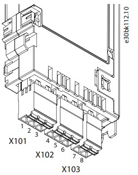 Illustration 15: Relay Option OC7R0 Terminals
Table 16: Functions for Relay Option OC7R0 Terminals
| Terminal X101 | Terminal X102 | Terminal X103 | |||
| Numbering | Function | Number | Function | Number | Function |
| 1 | Common | 4 | Common | 7 | Common |
| 2 | Normally Open (NO) | 5 | Normally Open (NO) | 8 | Normally Open (NO) |
| 3 | Normally Closed (NC) | 6 | Normally Closed (NC) | ||
The connectors are coded and cannot be exchanged in the control board.
See 6.6 Setup and Connection Examples for Relay Option OC7R0 for more information on wiring the option.
6.5 Relay Option OC7R0 Specifications
Relays are PELV galvanic isolated from supply voltage and other high voltage terminals, unless otherwise specified.
Table 17: Technical Specifications for Relay Option OC7R0
| Functions | Data |
| Number of relay outputs | 3 (2 NO/NC, 1 NO) |
| Maximum terminal load (AC-1): Resistive load | 250 V AC, 2 A |
| Maximum terminal load (AC-15): Inductive load @ cos =0.4 |
250 V AC, 0.2 A |
| Maximum terminal load (DC-1): Resistive load | 80 V DC, 2 A |
| Maximum terminal load (DC-13) : Inductive load | 24 V DC, 0.1 A |
| Minimum load | 24 V DC, 10 mA |
| 24 V AC, 20 mA | |
| Rated number of cycles (@2 A resistive load) | 400 000 switchings |
| Cable type | Cu, 75 °C (167 °F) |
| Cable size | Solid: 0.2–2.5 mm |
| (24–14 AWG) | |
| Flexible: 0.2–2.5 mm | |
| (24–14 AWG) | |
| Flexible with ferrule, without plastic sleeve: 0.25–2.5 mm | |
| (24–14 AWG) | |
| Flexible without ferrule, with plastic sleeve: 0.25–2.5 mm | |
| (24–14 AWG) | |
| Maximum cable length | 300 m (984 ft) |
| Maximum altitude | 4400 m (14400 ft) NOTICE – The operating altitude sets requirements on voltages. For the wiring diagrams for different operating altitudes, see 6.6.1 Wiring Diagrams for Different Operating Altitudes. |
| Ambient temperature | -30 °C…60 °C (-22 °F…140 °F) |
| Weight | 0.12 kg (0.26 lb) |
| Environment | Overvoltage category III/pollution degree 2 |
6.6 Setup and Connection Examples for Relay Option OC7R0
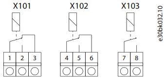
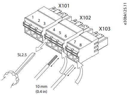 Illustration 17: Inserting Wires into the Relay Option OC7R0 Connectors
6.6.1 Wiring Diagrams for Different Operating Altitudes
- Operation up to 2000 m (6560 ft) altitude: Each relay can operate at different phase voltages. See Illustration 18.
- Operation above 2000 m (6560 ft) altitude: Operation with voltage above 50 V AC requires operation on the same phase voltage. See Illustration 19.
- Operation with mixed voltage (24 V) and high voltage is possible. High voltage must be on the same phase. See Illustration 20.
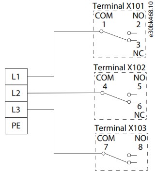
Illustration 18: Operation up to 2000 m (6560 ft) Altitude
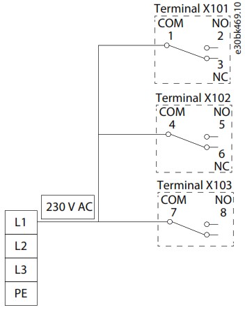
Illustration 19: Operation above 2000 m (6560 ft) Altitude with Voltage above 50 V AC
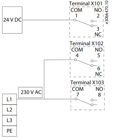
Illustration 20: Operation above 2000 m (6560 ft) Altitude with Mixed Voltages
6.7 Parameter Descriptions for Relay Option OC7R0
To set Relay output, see parameter group 5.26.1 General Digital Outputs.
Table 18: Digital Output Mapping for Relay Option OC7R0
| Bit number | Value |
| 15 | – |
| 14 | Relay 8 |
| 13 | Relay 5 |
| 12 | Relay 2 |
| 11 | – |
| 10 | – |
| 9 | – |
| 8 | – |
| 7 | – |
| 6 | – |
| 5 | – |
| 4 | – |
| 3 | – |
| 2 | – |
| 1 | – |
| 0 | – |
6.7.1 Status (Menu Index 9.3)
P 9.3.1 Digital Relay Bit Word
Description: Shows the bitwise status of each relay output, bit 12 for relay 2, bit 13 for relay 5, bit 14 for relay 8
| Default Value: NA | Parameter Type: Range (0 — 65535) | Parameter Number: 4909 |
| Unit: – | Data Type: WORD | Access Type: Read Only |
P 9.3.2 Relay X101
Description: Number of activations of Relay X101.
| Default Value: 0 | Parameter Type: Range (0 — 4294967295) | Parameter Number: 4910 |
| Unit: – | Data Type: UDINT | Access Type: Read Only |
P 9.3.3 Relay X102
Description: Number of activations of Relay X102.
| Default Value: 0 | Parameter Type: Range (0 — 4294967295) | Parameter Number: 4911 |
| Unit: – | Data Type: UDINT | Access Type: Read Only |
P 9.3.4 Relay X103
Description: Number of activations of Relay X103.
| Default Value: 0 | Parameter Type: Range (0 — 4294967295) | Parameter Number: 4912 |
| Unit: – | Data Type: UDINT | Access Type: Read Only |
Danfoss A/S
Ulsnaes 1
DK-6300 Graasten
drives.danfoss.com
Any information, including, but not limited to information on selection of product, its application or use, product design, weight, dimensions, capacity or any other technical data in product manuals, catalogues descriptions, advertisements, etc. and whether made available in writing, orally, electronically, online or via download, shall be considered informative, and is only binding if and to the extent, explicit reference is made in a quotation or order confirmation. Danfoss cannot accept any responsibility for possible errors in catalogues, brochures, videos and other material. Danfoss reserves the right to alter its products without notice. This also applies to products ordered but not delivered provided that such alterations can be made without changes to form, fit or function of the product. All trademarks in this material are property of Danfoss A/S or Danfoss group companies. Danfoss and the Danfoss logo are trademarks of Danfoss A/S. All rights reserved.

Danfoss A/S © 2023.10
AN341428219214en-000201 / 130R0383 | 6

Documents / Resources
 |
Danfoss iC7 Series Automation Frequency Converter [pdf] User Guide AQ390830267692en-000501, OC7M0, OC7R0, iC7 Series Automation Frequency Converter, iC7 Series, Automation Frequency Converter, Frequency Converter |
 |
Danfoss iC7 Series Automation Frequency Converter [pdf] Installation Guide AQ390830267692en-000101, OC7M0, iC7 Series Automation Frequency Converter, iC7 Series, Automation Frequency Converter, Frequency Converter, Converter |
 |
Danfoss iC7 Series Automation Frequency Converter [pdf] User Guide AQ390830267692en-000201, 136R0273, iC7 Series Automation Frequency Converter, iC7 Series, Automation Frequency Converter, Frequency Converter |