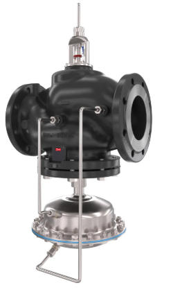
 Danfoss AFQM 2 Flow Controller with Integrated Control Valve
Safety Notes

Prior to assembly and commissioning to avoid injury of persons and damages of the devices, it is absolutely necessary to carefully read and observe these instructions. Necessary assembly, start-up, and maintenance work must be performed only by qualified, trained and authorized personnel.
Prior to assembly and maintenance work on the controller, the system must be:
- depressurized,
- cooled down,
- emptied and
- cleaned.
Please comply with the instructions of the system manufacturer or system operator.
Definition of Application
The controllers AFQM 2 and AFQMP 2 are used in connection with electrical actuators AMV(E) 55/56 and 65x for flow limitation and temperature control of water and water-glycol mixtures for heating, district heating and cooling system. The technical data on the rating plates determine the use
Mounting ❶

Permissible Installation Positions
All installation positions are allowed
Electrical actuator
Installation positions for electrical actuators AMV(E) have to be observed as well. Please see relevant Data Sheet.
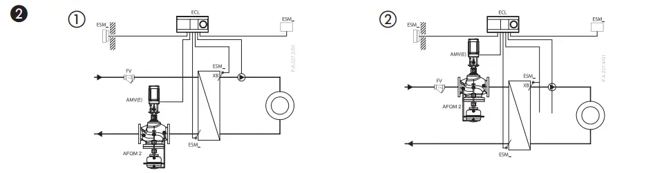
Place and Scheme of Installation ❷
- Return flow
- Supply
Valve Installation ❸
- Install strainer ① in front of valve.
- Rinse system before installing valve.
- Observe flow direction ② on the valve body.
 Flanges ③ in the pipeline system must be in parallel direction, the sealing surfaces must be clean and undamaged.
 - Install valve.
- Tighten screws crosswise in 3 steps up to the maximum torque.
Insulation ❹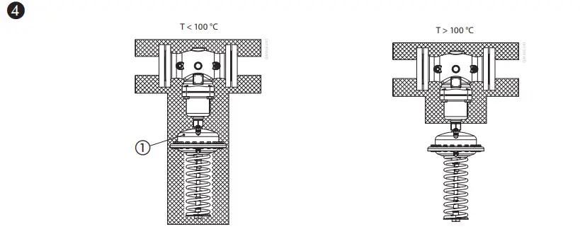
- DO NOT insulate the electrical actuator!
- The pressure actuator may be insulated up to a medium temperature of 100 °C.
Actuator and Valve Mounting ❺ AMV(E) 55/56
- Remove the connector ① by release the bolt of actuator using Allen key 4 mm.
- Tighten union nut ②, torque 3 Nm.
- Install the connector ① again to connect the spindle of actuator and valve.
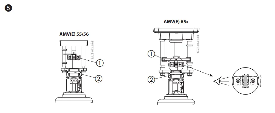
Read Instructions of AMV(E) 55/56 for wiring and setting.
AMV(E) 65X
- Install the actuator to the valve.
- Tighten the nuts ② to fix the ring.
- Connect stems ①.
- Tigten the connector ① again to connect the spindle of actuator and valve.
Read Instructions of AMV(E) 65x for wiring and setting.
Leak and Pressure Tests ❻
- Prior to pressure tests it is absolutely necessary to open the valve.
- Non-compliance may cause damages at the controller AFQM 2/AFQMP 2.


Open valve by means of the actuator:
- A AMV(E) 55/56
Adjust valve position manually using an Allen key (See instructions of AMV(E) 55/56 for manual operation). - B AMV(E) 65x
Manual adjustment of the valve depend on type of the AMV(E) 65x actuator (See instructions for particular type of AMV(E) 65x for manual operation).
When the impulse tube is installed, the max. operating pressure of *16 bar (PN 16) and *20 bar (PN25) must NOT be exceeded.
*DN depended
- Non-compliance may cause leaks at the actuator.
- In case of higher test pressures, remove impulse tubes ⑧ at the valve.
- Close connections at the valve with plug G1/4 ISO 228 ⑨.
- Observe nominal pressure ⑩ of the valve.
Max. test pressure is 1,5 × PN
Filling the System First Start-up ❼

First, ensure that valve is open. To open the valve see section 5 and read instructions for relevant type of the actuator.
The pressure ② at the valve output may exceed the pressure ① at the valve input only insignificantly. Non-compliance may cause damages at the Controller.
Differential Pressure Setting ❽
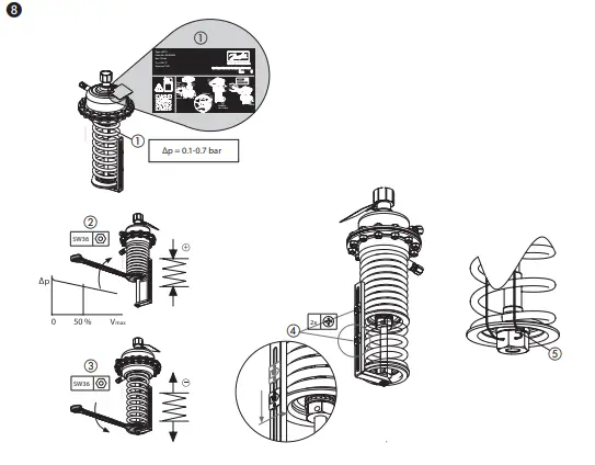
(only for AFQMP 2)
- Set-point range see rating plate ①
- Set flow rate on a motorized valve part to about 50 %.
- Adjustment:
- Turning to the right ② increases the set-point (stressing the spring)
- Turning to the left ③ reduces the set-point (un-stressing the spring)
- Set the differential pressure to the level needed to reach desired maximum flow
- The set-point adjuster ④ may be sealed.
- Release the not yet used pointer ⑤, move it to the set position and fix it with the screw
Flow Limitation Adjustment ❾
The connector between valve and actuator should be released and the actuator removed before the adjustment of flow to prevent any possible damage to the actuator. The adjustment of the flow is made by adjusting the valve stroke.
There are 2 possibilities:
- Adjustment with adjustment diagram see ❿ and ⓫.
- Adjustment with heat meter, see ⓬.
Adjustment with adjustment diagram ❿ ⓫
The system should not be in operation for adjustment. Setting curves are of informative nature. For more exact settings use flow meter values.


Valve stroke adjustment ❾
- Close valve by turning the adjusting screw ① up to its stop.
- Select diagram below necessary flow. See AFQM 2/AFQMP 2 adjustment diagrams ❿ ⓫.
 Turn adjusting screw ① by the No number to the right.
The adjustment of the valve stroke is completed.- The adjusting screw may be sealed (drilling).
Adjustment with heat meter ⓬
- Operate actuator manually or by control signal to retract the stem.
See the manual operation in instructions of AMV(E) 55/56/65x actuator. - Ensure that the system or a bypass ② is completely open.
- Observe indicator of heat meter.
- Increase of flow ❾ ①.
- Reduction of flow ❾ ②.
- As soon as the heat meter shows the required value, shortly throttle the system and re-open.
- Verify flow.
When flow adjustment is finished,the connector between valve and actuator should be reconnected and then start self-adjustment of actuator according to AMV(E) 55/56, AMV(E) 65x, instructions. The adjustment of the valve stroke is completed. - The adjusting screw may be sealed (drilling).

Dimensions ⓭
Note:
In case of membrane breakage, leakage through impulse tube can be higher than leakage rate stated in data sheet (≤ 0.01 % of kVS). 


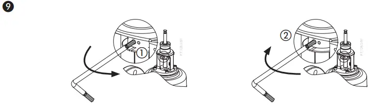
Troubleshooting
In the position when regulator is mounted with electrical actuator on top, air can get trapped in relievement chamber after the installation (and system filling up). In rare cases hammering noise at low opening can occur.
If this is the case, please de-air the control valve side (where electrical actuator is mounted) following next steps:

- Make sure the valve is not fully closed ①
- Insert pin in the hole and unscrew the stuffing box for a few turns (usually 2-3 full turns) ②
- Wait until there is no more air coming out
- Use the pin and screw the stuffing box back in (tightening torque 15 Nm) ④
Any information, including, but not limited to information on selection of product, its application or use, product design, weight, dimensions, capacity or any other technical data in product manuals, catalogues descriptions, advertisements, etc. and whether made available in writing, orally, electronically, online or via download, shall be considered informative, and is only binding if and to the extent, explicit reference is made in a quotation or order confirmation. Danfoss cannot accept any responsibility for possible errors in catalogues, brochures, videos and other material. Danfoss reserves the right to alter its products without notice. This also applies to products ordered but not delivered provided that such alterations can be made without changes to form, fit or function of the product. All trademarks in this material are property of Danfoss A/S or Danfoss group companies. Danfoss and the Danfoss logo are trademarks of Danfoss A/S. All rights reserved.
Frequently Asked Questions
- Q: Is this product suitable for use in high-pressure systems?
A: The product is rated up to PN 40, suitable for various pressure requirements within the specified range. - Q: Can I adjust the flow manually without affecting the integrated control valve?
A: Yes, you can adjust the flow manually using the turns indicator while maintaining control valve integrity.
Documents / Resources
 |
Danfoss AFQM 2 Flow Controller with Integrated Control Valve [pdf] User Guide AFQM 2, AFQMP 2 PN16, 25, 40, AFQM 2 Flow Controller with Integrated Control Valve, AFQM 2, Flow Controller with Integrated Control Valve, Integrated Control Valve, Control Valve |


