Danfoss 80Z790.11 Gas Detection Sensor

Specifications
- Product: Service Tool for Danfoss Gas Detection Sensor (DGS)
- Model: DGS JP5
- Input Voltage: 24V AC/DC
- Analog Output: Open (0-20mA), Closed (0-10V)
- Digital Inputs: DI_01, S&H supply
- LEDs: Yellow/Green/Red
- Communication: Modbus A+
- Baud Rate: Open (19200 Baud), Closed (38400 Baud)
Installation Steps
- Plug-in Service Tool plug.
- Await display light.
- Follow instructions in the DGS User Guide.
Diagram Description
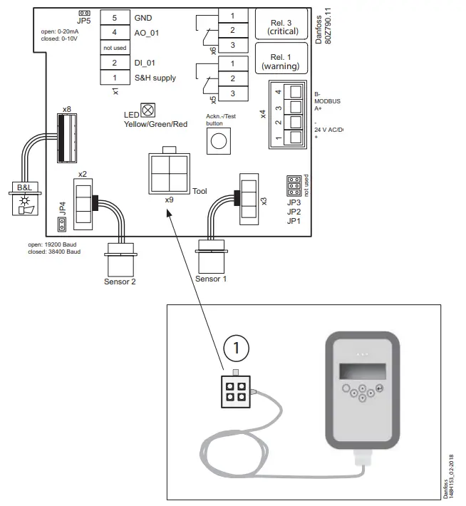
The diagram shows the layout of the Danfoss Gas Detection Sensor (DGS) with various connection points labeled. Key components include LED indicators, relays, MODBUS interface, and sensor connections.
FAQ
- Q: What should I do if the display light does not turn on?
A: Check the power source connection and ensure that the Service Tool plug is securely inserted. If the issue persists, consult the troubleshooting section in the user manual. - Q: How can I change the communication baud rate?
A: To change the baud rate, open JP2 for 19200 Baud or close it for 38400 Baud. Refer to the user manual for detailed instructions. - Q: What do the different LED colors indicate?
A: Yellow, Green, and Red LEDs may indicate different statuses or alerts. Consult the user manual for a detailed explanation of LED indications.
Documents / Resources
 |
Danfoss 80Z790.11 Gas Detection Sensor [pdf] Installation Guide 80Z790.11 Gas Detection Sensor, 80Z790.11, Gas Detection Sensor, Detection Sensor, Sensor |


