Cosel CBS-series Converters Bus Converter Power Module Type
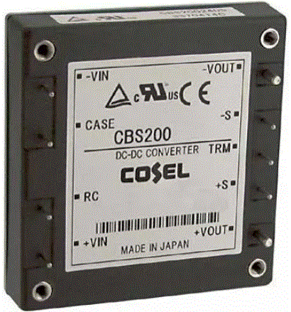
Product Information
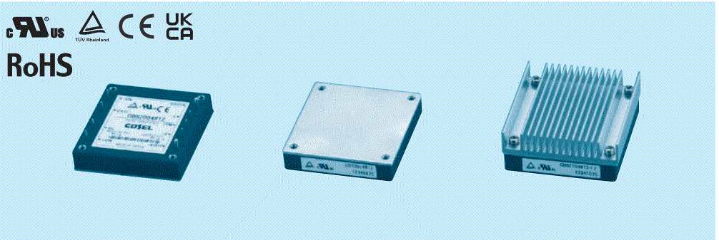
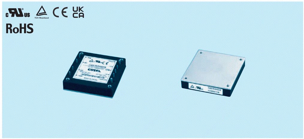
The DC-DC Converters Bus Converter is a low-profile isolated power module type. It is a compact HALF BRICK converter that is commonly used in the telecommunication market. The converter offers high efficiency, high density, and high reliability. It does not have built-in aluminum and tantalum electrolytic capacitors, and it features built-in overcurrent, overvoltage, and thermal protection circuits. The converter also has a remote ON/OFF function and a mounting hole (M3 tapped). It is compliant with CE marking, Low Voltage Directive, RoHS Directive, UKCA marking, Electrical Equipment Safety Regulations, and RoHS Regulations. The safety agency approvals include UL60950-1, C-UL recognized, and TuV approved. The converter comes with a 5-year warranty and optional parts such as a heat sink.
Product Usage Instructions
- Ensure that the input voltage of the DC-DC converter is within the specified range. The available input voltage options are DC18 – 36V or DC36 – 76V.
- Select the desired output voltage from the available options: 1.8V, 2.5V, 3.3V, 5V, or 12V.
- Refer to the model specifications to determine the maximum output wattage for the selected output voltage.
- If required, choose optional features such as remote ON/OFF or mounting hole.
- If additional cooling is needed, consider adding a heat sink as an optional part.
- Based on the chosen specifications, refer to the model number table to find the appropriate model code.
- Ensure that the DC-DC converter is properly installed and connected according to the provided guidelines.
- Verify that the output voltage of the converter is adjusted within the specified range, if necessary.
- Take note of the overcurrent protection, overvoltage protection, and other safety features provided by the converter.
- If remote sensing or remote ON/OFF functionality is required, follow the instructions provided to enable and control these features.
For more detailed information and technical specifications, please refer to the product manual available at http://www.cosel.co.jp/en/.
Feature
- Compact DC-DC Converter, ”HALF BRICK” which has been standard size for Telecommunication Market
- High efficiency
- High density
- High reliability : not built-in aluminum and tantalum electrolytic capacitor
- Built-in overcurrent, overvoltage and thermal protection circuits
- Built-in remote ON/OFF
- Mounting hole (M3 tapped)
CE marking
- Low Voltage Directive
- RoHS Directive
- UKCA marking
- Electrical Equipment Safety Regulations
- RoHS Regulations
- Safety agency approvals
- UL60950-1, C-UL recognized, TuV approved
- 5-year warranty
Optional parts
| Optional parts | Model |
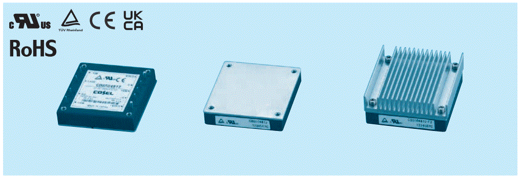
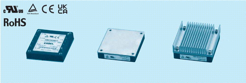
| Heat sink | CBS50, CBS100, CBS200 |
DC-DC Converters Bus Converter.Power Module Type
CBS50
Ordering information

- Series name
- Single output
- Output wattage
- Input voltage
- 24 : DC18 – 36V
- 48 : DC36 – 76V
- Output voltage
- Optional
- R: with Remote ON/OFF
- Positive logic control
- T: with Mounting hole
- f3.4 thru
- FO: with Additio Heat sink
| MODEL | CBS50241R8 | CBS50242R5 | CBS502403 | CBS502405 | CBS502412 | CBS502415 | CBS502424 | CBS502428 |
| MAX OUTPUT WATTAGE[W] | 21.06 | 29.25 | 38.6 | 50.0 | 50.4 | 51.0 | 50.4 | 50.4 |
| DC OUTPUT | 1.8V 11.7A | 2.5V 11.7A | 3.3V 11.7A | 5V 10A | 12V 4.2A | 15V 3.4A | 24V 2.1A | 28V 1.8A |
SPECIFICATIONS
| MODEL | CBS50241R8 | CBS50242R5 | CBS502403 | CBS502405 | CBS502412 | CBS502415 | CBS502424 | CBS502428 | ||
|
INPUT |
VOLTAGE[V] | DC18 – 36 | ||||||||
| CURRENT[A] *1 | 1.24typ | 1.58typ | 2.04typ | 2.48typ | 2.39typ | 2.44typ | 2.41typ | 2.41typ | ||
| EFFICIENCY[%] *1 | 71typ | 77typ | 79typ | 84typ | 88typ | 87typ | 87typ | 87typ | ||
|
OUTPUT |
VOLTAGE[V] | 1.8 | 2.5 | 3.3 | 5 | 12 | 15 | 24 | 28 | |
| CURRENT[A] | 11.7 | 11.7 | 11.7 | 10 | 4.2 | 3.4 | 2.1 | 1.8 | ||
| LINE REGULATION[mV] | 10max | 10max | 10max | 10max | 24max | 30max | 48max | 56max | ||
| LOAD REGULATION[mV] | 10max | 10max | 10max | 10max | 24max | 30max | 48max | 56max | ||
| RIPPLE[mVp-p] | -20to +100C*2 | 80max | 80max | 80max | 80max | 120max | 120max | 120max | 120max | |
| -40 to -20C*2 | 120max | 120max | 120max | 120max | 150max | 150max | 150max | 150max | ||
| RIPPLE NOISE[mVp-p] | -20to +100C*2 | 120max | 120max | 120max | 120max | 150max | 150max | 150max | 150max | |
| -40 to -20C*2 | 200max | 200max | 200max | 200max | 200max | 200max | 250max | 250max | ||
| TEMPERATURE REGULATION[mV] | 0 to +65C | 35max | 35max | 35max | 50max | 120max | 150max | 240max | 280max | |
| -40 to +100C | 66max | 66max | 66max | 100max | 240max | 300max | 480max | 560max | ||
| DRIFT[mV] *3 | 16max | 16max | 16max | 20max | 40max | 60max | 90max | 90max | ||
| START-UP TIME[ms] | 200max (DCIN 24V, Io=100%) | |||||||||
| OUTPUT VOLTAGE ADJUSTMENT RANGE[V] *4 | Fixed (TRM pin open), adjustable by external resistor | |||||||||
| 1.70 – 1.98 | 1.98 – 2.75 | 1.98 – 3.63 | 3.0 – 5.5 | 7.2 – 13.2 | 9.0 – 16.5 | 14.4 – 26.4 | 16.8 – 30.8 | |||
| OUTPUT VOLTAGE SETTING[V] | 1.77 – 1.88 | 2.46 – 2.61 | 3.25 – 3.45 | 4.90 – 5.20 | 11.74 – 12.46 | 14.55 – 15.45 | 23.28 – 24.72 | 27.16 – 28.84 | ||
|
PROTECTION CIRCUIT AND OTHERS |
OVERCURRENT PROTECTION | Works over 105% of rating and recovers automatically | ||||||||
| OVERVOLTAGE PROTECTION[V] | 2.16 – 2.88 | 3.00 – 4.00 | 4.00 – 5.50 | 5.75 – 7.00 | 13.80 – 16.80 | 17.25 – 21.00 | 27.60 – 33.60 | 32.20 – 39.20 | ||
| REMOTE SENSING | Provided | |||||||||
| REMOTE ON/OFF | Provided (Negative logic L : ON, H : OFF) | |||||||||
SPECIFICATIONS
| MODEL | CBS50481R8 | CBS50482R5 | CBS504803 | CBS504805 | CBS504812 | CBS504815 | CBS504824 | CBS504828 | ||
|
INPUT |
VOLTAGE[V] | DC36 – 76 | ||||||||
| CURRENT[A] *1 | 0.62typ | 0.79typ | 1.01typ | 1.23typ | 1.18typ | 1.21typ | 1.19typ | 1.19typ | ||
| EFFICIENCY[%] *1 | 71typ | 77typ | 80typ | 85typ | 89typ | 88typ | 88typ | 88typ | ||
|
OUTPUT |
VOLTAGE[V] | 1.8 | 2.5 | 3.3 | 5 | 12 | 15 | 24 | 28 | |
| CURRENT[A] | 11.7 | 11.7 | 11.7 | 10 | 4.2 | 3.4 | 2.1 | 1.8 | ||
| LINE REGULATION[mV] | 10max | 10max | 10max | 10max | 24max | 30max | 48max | 56max | ||
| LOAD REGULATION[mV] | 10max | 10max | 10max | 10max | 24max | 30max | 48max | 56max | ||
| RIPPLE[mVp-p] | -20to +100C*2 | 80max | 80max | 80max | 80max | 120max | 120max | 120max | 120max | |
| -40 to -20C*2 | 120max | 120max | 120max | 120max | 150max | 150max | 150max | 150max | ||
| RIPPLE NOISE[mVp-p] | -20to +100C*2 | 120max | 120max | 120max | 120max | 150max | 150max | 150max | 150max | |
| -40 to -20C*2 | 200max | 200max | 200max | 200max | 200max | 200max | 250max | 250max | ||
| TEMPERATURE REGULATION[mV] | 0 to +65C | 35max | 35max | 35max | 50max | 120max | 150max | 240max | 280max | |
| -40 to +100C | 66max | 66max | 66max | 100max | 240max | 300max | 480max | 560max | ||
| DRIFT[mV] *3 | 16max | 16max | 16max | 20max | 40max | 60max | 90max | 90max | ||
| START-UP TIME[ms] | 200max (DCIN 48V, Io=100%) | |||||||||
| OUTPUT VOLTAGE ADJUSTMENT RANGE[V] *4 | Fixed (TRM pin open), adjustable by external resistor | |||||||||
| 1.70 – 1.98 | 1.98 -2.75 | 1.98 – 3.63 | 3.0 – 5.5 | 7.2 – 13.2 | 9.0 – 16.5 | 14.4 – 26.4 | 16.8 – 30.8 | |||
| OUTPUT VOLTAGE SETTING[V] | 1.77 – 1.88 | 2.46 -2.61 | 3.25 – 3.45 | 4.90 – 5.20 | 11.74 – 12.46 | 14.55 – 15.45 | 23.28 – 24.72 | 27.16 – 28.84 | ||
|
PROTECTION CIRCUIT AND OTHERS |
OVERCURRENT PROTECTION | Works over 105% of rating and recovers automatically | ||||||||
| OVERVOLTAGE PROTECTION[V] | 2.16 – 2.88 | 3.00 – 4.00 | 4.00 – 5.50 | 5.75 – 7.00 | 13.80 – 16.80 | 17.25 – 21.00 | 27.60 – 33.60 | 32.20 – 39.20 | ||
| REMOTE SENSING | Provided | |||||||||
| REMOTE ON/OFF | Provided (Negative logic L : ON, H : OFF) | |||||||||
GENERAL SPECIFICATIONS
|
ISOLATION |
INPUT-OUTPUT | DC1,500V or AC1,000V 1minute, Cutoff current = 10mA, DC500V 50MW min(20t15C) |
| INPUT-CASE PIN, BASE PLATE | DC1,500V or AC1,000V 1minute, Cutoff current = 10mA, DC500V 50MW min(20t15C) | |
| OUTPUT-CASE PIN, BASE PLATE | AC500V 1minute, Cutoff current = 100mA, DC500V 50MW min (20t15C) | |
|
ENVIRONMENT |
OPERATING TEMP.,HUMID.AND ALTITUDE | -40 to +100C (On aluminum base plate), 20 – 95%RH (Non condensing) (Refer to “Derating”), 3,000m (10,000feet) max |
| STORAGE TEMP.,HUMID.AND ALTITUDE | -40 to +100C, 20 – 95%RH (Non condensing), 9,000m (30,000feet) max | |
| VIBRATION | 10 – 55Hz, 49.0m/s2 (5G), 3minutes period, 60minutes each along X, Y and Z axis | |
| IMPACT | 196.1m/s2 (20G), 11ms, once each along X, Y and Z axis | |
| SAFETY | AGENCY APPROVALS | UL60950-1, C-UL, EN62368-1 |
| OTHERS | CASE SIZE/WEIGHT | 57.9X12.7X61.0mm [2.28X0.5X2.4 inches](WXHXD) / 83g max |
| COOLING METHOD | Conduction cooling (e.g. heat radiation from the aluminum base plate to the attached heat sink) |
- At rated input(DC24V,DC48V) and rated load.
- Ripple and ripple noise is measured by using measuring board with recommended capacitor Co & the film capacitor 0.1mF.
Measured by 20MHz oscilloscope or Ripple-Noise meter (Equivalent to KEISOKU-GIKEN:RM101). - Drift is the change in DC output for an eight hour period after a half-hour warm-up at 25C, with the input voltage held constant at the rated input/output.
- When the input voltage is in the range of DC18 – 20V, DC36 – 40V, output voltage adjustment range is 60 – 105% (except for 1R8/2R5).
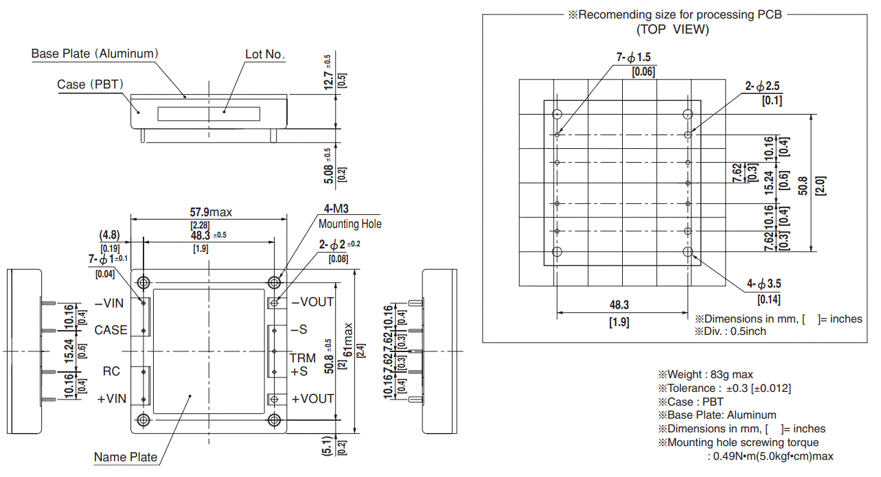
External view
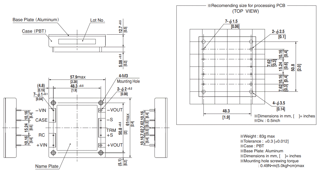
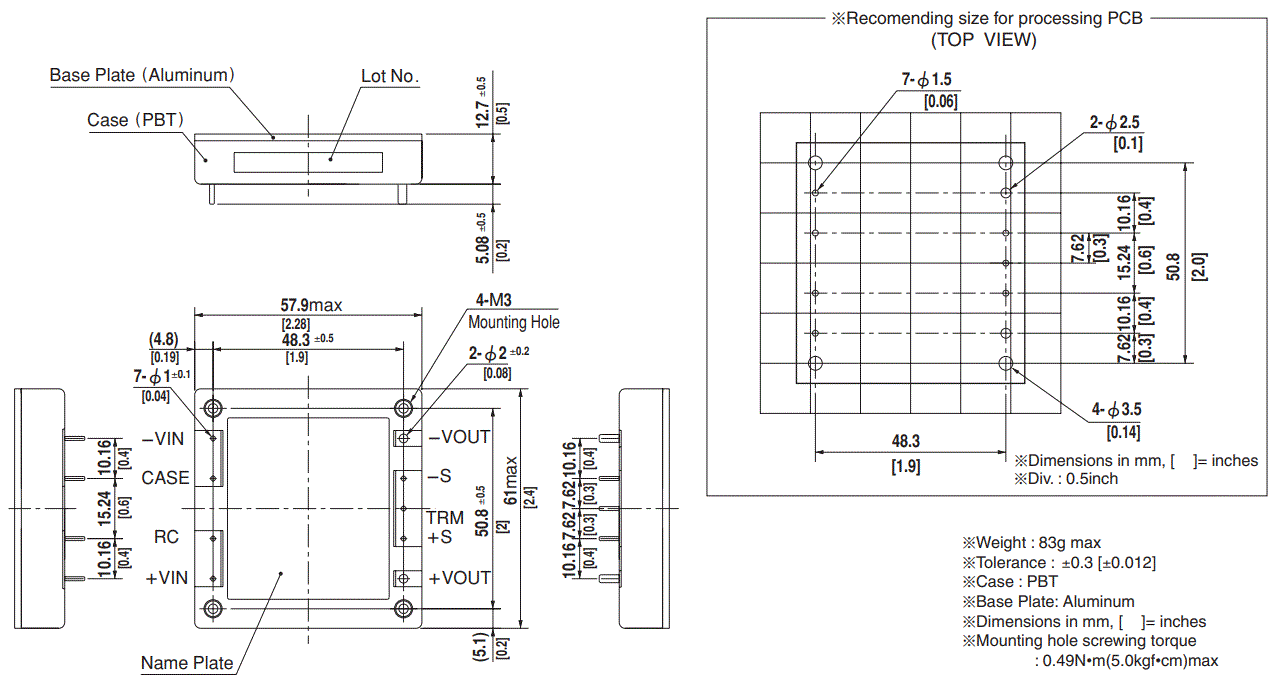
- Weight : 83g max
- Tolerance : 0.3 [±0.012]
- Case : PBT
- Base Plate: Aluminum
- Dimensions in mm, [ ]= inches
- Mounting hole screwing torque
- 0.49N•m(5.0kgf•cm)max
Performance data

DC-DC Converters Bus Converter.Power Module Type
Ordering information
- Series name
- Single output
- Output wattage
- Input voltage
24: DC18 – 36V
48: DC36 – 76V - Output voltage
- Optional
R : with Remote ON/OFF
Positive logic control
T : with Mounting hole
f3.4 thru
FO: with Addition of a Heat sink

| MODEL | CBS100241R8 | CBS100242R5 | CBS1002403 | CBS1002405 | CBS1002412 | CBS1002415 | CBS1002424 | CBS1002428 |
| MAX OUTPUT WATTAGE[W] | 42.12 | 58.50 | 77.2 | 100.0 | 100.8 | 100.5 | 100.8 | 100.8 |
| DC OUTPUT | 1.8V 23.4A | 2.5V 23.4A | 3.3V 23.4A | 5V 20A | 12V 8.4A | 15V 6.7A | 24V 4.2A | 28V 3.6A |
SPECIFICATIONS
| MODEL | CBS100241R8 | CBS100242R5 | CBS1002403 | CBS1002405 | CBS1002412 | CBS1002415 | CBS1002424 | CBS1002428 | ||
|
INPUT |
VOLTAGE[V] | DC18 – 36 | ||||||||
| CURRENT[A] *1 | 2.47typ | 3.17typ | 4.07typ | 5.02typ | 4.77typ | 4.81typ | 4.83typ | 4.83typ | ||
| EFFICIENCY[%] *1 | 71typ | 77typ | 79typ | 83typ | 88typ | 87typ | 87typ | 87typ | ||
|
OUTPUT |
VOLTAGE[V] | 1.8 | 2.5 | 3.3 | 5 | 12 | 15 | 24 | 28 | |
| CURRENT[A] | 23.4 | 23.4 | 23.4 | 20 | 8.4 | 6.7 | 4.2 | 3.6 | ||
| LINE REGULATION[mV] | 10max | 10max | 10max | 10max | 24max | 30max | 48max | 56max | ||
| LOAD REGULATION[mV] | 10max | 10max | 10max | 10max | 24max | 30max | 48max | 56max | ||
| RIPPLE[mVp-p] | -20to +100C*2 | 80max | 80max | 80max | 80max | 120max | 120max | 120max | 120max | |
| -40 to -20C*2 | 120max | 120max | 120max | 120max | 150max | 150max | 150max | 150max | ||
| RIPPLE NOISE[mVp-p] | -20to +100C*2 | 120max | 120max | 120max | 120max | 150max | 150max | 150max | 150max | |
| -40 to -20C*2 | 200max | 200max | 200max | 200max | 200max | 200max | 250max | 250max | ||
| TEMPERATURE REGULATION[mV] | 0 to +65C | 35max | 35max | 35max | 50max | 120max | 150max | 240max | 280max | |
| -40 to +100C | 66max | 66max | 66max | 100max | 240max | 300max | 480max | 560max | ||
| DRIFT[mV] *3 | 16max | 16max | 16max | 20max | 40max | 60max | 90max | 90max | ||
| START-UP TIME[ms] | 200max (DCIN 24V, Io=100%) | |||||||||
| OUTPUT VOLTAGE ADJUSTMENT RANGE[V] *4 | Fixed (TRM pin open), adjustable by external resistor | |||||||||
| 1.70 – 1.98 | 1.98 – 2.75 | 1.98 – 3.63 | 3.0 – 5.5 | 7.2 – 13.2 | 9.0 – 16.5 | 14.4 – 26.4 | 16.8 – 30.8 | |||
| OUTPUT VOLTAGE SETTING[V] | 1.77 – 1.88 | 2.46 – 2.61 | 3.25 – 3.45 | 4.90 – 5.20 | 11.74 – 12.46 | 14.55 – 15.45 | 23.28 – 24.72 | 27.16 – 28.84 | ||
|
PROTECTION CIRCUIT AND OTHERS |
OVERCURRENT PROTECTION | Works over 105% of rating and recovers automatically | ||||||||
| OVERVOLTAGE PROTECTION[V] | 2.16 – 2.88 | 3.00 – 4.00 | 4.00 – 5.50 | 5.75 – 7.00 | 13.80 – 16.80 | 17.25 – 21.00 | 27.60 – 33.60 | 32.20 – 39.20 | ||
| REMOTE SENSING | Provided | |||||||||
| REMOTE ON/OFF | Provided (Negative logic L : ON, H : OFF) | |||||||||
| MODEL | CBS100481R8 | CBS100482R5 | CBS1004803 | CBS1004805 | CBS1004812 | CBS1004815 | CBS1004824 | CBS1004828 |
| MAX OUTPUT WATTAGE[W] | 42.12 | 58.50 | 77.2 | 100.0 | 100.8 | 100.5 | 100.8 | 100.8 |
| DC OUTPUT | 1.8V 23.4A | 2.5V 23.4A | 3.3V 23.4A | 5V 20A | 12V 8.4A | 15V 6.7A | 24V 4.2A | 28V 3.6A |
SPECIFICATIONS
| MODEL | CBS100481R8 | CBS100482R5 | CBS1004803 | CBS1004805 | CBS1004812 | CBS1004815 | CBS1004824 | CBS1004828 | ||
|
INPUT |
VOLTAGE[V] | DC36 – 76 | ||||||||
| CURRENT[A] *1 | 1.24typ | 1.58typ | 2.01typ | 2.48typ | 2.36typ | 2.38typ | 2.39typ | 2.39typ | ||
| EFFICIENCY[%] *1 | 71typ | 77typ | 80typ | 84typ | 89typ | 88typ | 88typ | 88typ | ||
|
OUTPUT |
VOLTAGE[V] | 1.8 | 2.5 | 3.3 | 5 | 12 | 15 | 24 | 28 | |
| CURRENT[A] | 23.4 | 23.4 | 23.4 | 20 | 8.4 | 6.7 | 4.2 | 3.6 | ||
| LINE REGULATION[mV] | 10max | 10max | 10max | 10max | 24max | 30max | 48max | 56max | ||
| LOAD REGULATION[mV] | 10max | 10max | 10max | 10max | 24max | 30max | 48max | 56max | ||
| RIPPLE[mVp-p] | -20to +100C*2 | 80max | 80max | 80max | 80max | 120max | 120max | 120max | 120max | |
| -40 to -20C*2 | 120max | 120max | 120max | 120max | 150max | 150max | 150max | 150max | ||
| RIPPLE NOISE[mVp-p] | -20to +100C*2 | 120max | 120max | 120max | 120max | 150max | 150max | 150max | 150max | |
| -40 to -20C*2 | 200max | 200max | 200max | 200max | 200max | 200max | 250max | 250max | ||
| TEMPERATURE REGULATION[mV] | 0 to +65C | 35max | 35max | 35max | 50max | 120max | 150max | 240max | 280max | |
| -40 to +100C | 66max | 66max | 66max | 100max | 240max | 300max | 480max | 560max | ||
| DRIFT[mV] *3 | 16max | 16max | 16max | 20max | 40max | 60max | 90max | 90max | ||
| START-UP TIME[ms] | 200max (DCIN 48V, Io=100%) | |||||||||
| OUTPUT VOLTAGE ADJUSTMENT RANGE[V] *4 | Fixed (TRM pin open), adjustable by external resistor | |||||||||
| 1.70 – 1.98 | 1.98 -2.75 | 1.98 – 3.63 | 3.0 – 5.5 | 7.2 – 13.2 | 9.0 – 16.5 | 14.4 – 26.4 | 16.8 – 30.8 | |||
| OUTPUT VOLTAGE SETTING[V] | 1.77 – 1.88 | 2.46 -2.61 | 3.25 – 3.45 | 4.90 – 5.20 | 11.74 – 12.46 | 14.55 – 15.45 | 23.28 – 24.72 | 27.16 – 28.84 | ||
|
PROTECTION CIRCUIT AND OTHERS |
OVERCURRENT PROTECTION | Works over 105% of rating and recovers automatically | ||||||||
| OVERVOLTAGE PROTECTION[V] | 2.16 – 2.88 | 3.00 – 4.00 | 4.00 – 5.50 | 5.75 – 7.00 | 13.80 – 16.80 | 17.25 – 21.00 | 27.60 – 33.60 | 32.20 – 39.20 | ||
| REMOTE SENSING | Provided | |||||||||
| REMOTE ON/OFF | Provided (Negative logic L : ON, H : OFF) | |||||||||
GENERAL SPECIFICATIONS
|
ISOLATION |
INPUT-OUTPUT | DC1,500V or AC1,000V 1minute, Cutoff current = 10mA, DC500V 50MW min(20t15C) |
| INPUT-CASE PIN, BASE PLATE | DC1,500V or AC1,000V 1minute, Cutoff current = 10mA, DC500V 50MW min(20t15C) | |
| OUTPUT-CASE PIN, BASE PLATE | AC500V 1minute, Cutoff current = 100mA, DC500V 50MW min (20t15C) | |
|
ENVIRONMENT |
OPERATING TEMP.,HUMID.AND ALTITUDE | -40 to +100C (On aluminum base plate), 20 – 95%RH (Non condensing) (Refer to “Derating”), 3,000m (10,000feet) max |
| STORAGE TEMP.,HUMID.AND ALTITUDE | -40 to +100C, 20 – 95%RH (Non condensing), 9,000m (30,000feet) max | |
| VIBRATION | 10 – 55Hz, 49.0m/s2 (5G), 3minutes period, 60minutes each along X, Y and Z axis | |
| IMPACT | 196.1m/s2 (20G), 11ms, once each along X, Y and Z axis | |
| SAFETY | AGENCY APPROVALS | UL60950-1, C-UL, EN62368-1 |
| OTHERS | CASE SIZE/WEIGHT | 57.9X12.7X61.0mm [2.28X0.5X2.4 inches] (WXHXD) / 83g max |
| COOLING METHOD | Conduction cooling (e.g. heat radiation from the aluminum base plate to the attached heat sink) |
- At rated input(DC24V,DC48V) and rated load.
- Ripple and ripple noise is measured by using measuring board with recommended capacitor Co & the film capacitor 0.1mF.
Measured by 20MHz oscilloscope or Ripple-Noise meter (Equivalent to KEISOKU-GIKEN:RM101). - Drift is the change in DC output for an eight hour period after a half-hour warm-up at 25C, with the input voltage held constant at the rated input/output.
- When the input voltage is in the range of DC18 – 20V, DC36 – 40V output voltage adjustment range is 60 – 105% (except for 1R8/2R5).
External view
Performance data

DC-DC Converters Bus Converter.Power Module Type
CBS200
Ordering information

- Series name
- Single output
- Output wattage
- Input voltage
24: DC18 – 36V
48: DC36 – 76V - Output voltage
- Optional
R : with Remote ON/OFF
Positive logic control
T : with Mounting hole
f3.4 thru
FO: with Addition of a Heat sink
| MODEL | CBS200241R8 | CBS200242R5 | CBS2002403 | CBS2002405 | CBS2002412 | CBS2002415 | CBS2002424 | CBS2002428 |
| MAX OUTPUT WATTAGE[W] | 63.00 | 87.50 | 115.5 | 150.0 | 200.4 | 201.0 | 201.6 | 201.6 |
| DC OUTPUT | 1.8V 35A | 2.5V 35A | 3.3V 35A | 5V 30A | 12V 16.7A | 15V 13.4A | 24V 8.4A | 28V 7.2A |
SPECIFICATIONS
| MODEL | CBS200241R8 | CBS200242R5 | CBS2002403 | CBS2002405 | CBS2002412 | CBS2002415 | CBS2002424 | CBS2002428 | ||
|
INPUT |
VOLTAGE[V] | DC18 – 36 | ||||||||
| CURRENT[A] *1 | 3.75typ | 4.80typ | 6.09typ | 7.62typ | 9.60typ | 9.63typ | 9.66typ | 9.66typ | ||
| EFFICIENCY[%] *1 | 70typ | 76typ | 79typ | 82typ | 87typ | 87typ | 87typ | 87typ | ||
|
OUTPUT |
VOLTAGE[V] | 1.8 | 2.5 | 3.3 | 5 | 12 | 15 | 24 | 28 | |
| CURRENT[A] | 35 | 35 | 35 | 30 | 16.7 | 13.4 | 8.4 | 7.2 | ||
| LINE REGULATION[mV] | 10max | 10max | 10max | 10max | 24max | 30max | 48max | 56max | ||
| LOAD REGULATION[mV] | 10max | 10max | 10max | 10max | 24max | 30max | 48max | 56max | ||
| RIPPLE[mVp-p] | -20to +100C*2 | 80max | 80max | 80max | 80max | 120max | 120max | 120max | 120max | |
| -40 to -20C*2 | 120max | 120max | 120max | 120max | 150max | 150max | 150max | 150max | ||
| RIPPLE NOISE[mVp-p] | -20to +100C*2 | 120max | 120max | 120max | 120max | 150max | 150max | 150max | 150max | |
| -40 to -20C*2 | 200max | 200max | 200max | 200max | 200max | 200max | 250max | 250max | ||
| TEMPERATURE REGULATION[mV] | 0 to +65C | 35max | 35max | 35max | 50max | 120max | 150max | 240max | 280max | |
| -40 to +100C | 66max | 66max | 66max | 100max | 240max | 300max | 480max | 560max | ||
| DRIFT[mV] *3 | 16max | 16max | 16max | 20max | 40max | 60max | 90max | 90max | ||
| START-UP TIME[ms] | 200max (DCIN 24V, Io=100%) | |||||||||
| OUTPUT VOLTAGE ADJUSTMENT RANGE[V] *4 | Fixed (TRM pin open), adjustable by external resistor | |||||||||
| 1.70 – 1.98 | 1.98 – 2.75 | 1.98 – 3.63 | 3.0 – 5.5 | 7.2 – 13.2 | 9.0 – 16.5 | 14.4 – 26.4 | 16.8 – 30.8 | |||
| OUTPUT VOLTAGE SETTING[V] | 1.77 – 1.88 | 2.46 – 2.61 | 3.25 – 3.45 | 4.90 – 5.20 | 11.74 – 12.46 | 14.55 – 15.45 | 23.28 – 24.72 | 27.16 – 28.84 | ||
|
PROTECTION CIRCUIT AND OTHERS |
OVERCURRENT PROTECTION | Works over 105% of rating and recovers automatically | ||||||||
| OVERVOLTAGE PROTECTION[V] | 2.16 – 2.88 | 3.00 – 4.00 | 4.00 – 5.50 | 5.75 – 7.00 | 13.80 – 16.80 | 17.25 – 21.00 | 27.60 – 33.60 | 32.20 – 39.20 | ||
| REMOTE SENSING | Provided | |||||||||
| REMOTE ON/OFF | Provided (Negative logic L : ON, H : OFF) | |||||||||
| MODEL | CBS200481R8 | CBS200482R5 | CBS2004803 | CBS2004805 | CBS2004812 | CBS2004815 | CBS2004824 | CBS2004828 | CBS2004848 |
| MAX OUTPUT WATTAGE[W] | 63.00 | 87.50 | 115.5 | 150.0 | 200.4 | 201.0 | 201.6 | 201.6 | 201.6 |
| DC OUTPUT | 1.8V 35A | 2.5V 35A | 3.3V 35A | 5V 30A | 12V 16.7A | 15V 13.4A | 24V 8.4A | 28V 7.2A | 48V 4.2A |
SPECIFICATIONS
| MODEL | CBS200481R8 | CBS200482R5 | CBS2004803 | CBS2004805 | CBS2004812 | CBS2004815 | CBS2004824 | CBS2004828 | CBS2004848 | ||
|
INPUT |
VOLTAGE[V] | DC36 – 76 | |||||||||
| CURRENT[A] *1 | 1.88typ | 2.40typ | 3.01typ | 3.77typ | 4.74typ | 4.76typ | 4.77typ | 4.77typ | 4.77typ | ||
| EFFICIENCY[%] *1 | 70typ | 76typ | 80typ | 83typ | 88typ | 88typ | 88typ | 88typ | 88typ | ||
|
OUTPUT |
VOLTAGE[V] | 1.8 | 2.5 | 3.3 | 5 | 12 | 15 | 24 | 28 | 48 | |
| CURRENT[A] | 35 | 35 | 35 | 30 | 16.7 | 13.4 | 8.4 | 7.2 | 4.2 | ||
| LINE REGULATION[mV] | 10max | 10max | 10max | 10max | 24max | 30max | 48max | 56max | 96max | ||
| LOAD REGULATION[mV] | 10max | 10max | 10max | 10max | 24max | 30max | 48max | 56max | 96max | ||
| RIPPLE[mVp-p] | -20to +100C*2 | 80max | 80max | 80max | 80max | 120max | 120max | 120max | 120max | 200max | |
| -40 to -20C*2 | 120max | 120max | 120max | 120max | 150max | 150max | 150max | 150max | 250max | ||
| RIPPLE NOISE[mVp-p] | -20to +100C*2 | 120max | 120max | 120max | 120max | 150max | 150max | 150max | 150max | 250max | |
| -40 to -20C*2 | 200max | 200max | 200max | 200max | 200max | 200max | 250max | 250max | 400max | ||
| TEMPERATURE REGULATION[mV] | 0 to +65C | 35max | 35max | 35max | 50max | 120max | 150max | 240max | 280max | 480max | |
| -40 to +100C | 66max | 66max | 66max | 100max | 240max | 300max | 480max | 560max | 960max | ||
| DRIFT[mV] *3 | 16max | 16max | 16max | 20max | 40max | 60max | 90max | 90max | 180max | ||
| START-UP TIME[ms] | 200max (DCIN 48V, Io=100%) | ||||||||||
| OUTPUT VOLTAGE ADJUSTMENT RANGE[V] *4 | Fixed (TRM pin open), adjustable by external resistor | ||||||||||
| 1.70 – 1.98 | 1.98 -2.75 | 1.98 – 3.63 | 3.0 – 5.5 | 7.2 – 13.2 | 9.0 – 16.5 | 14.4 – 26.4 | 16.8 – 30.8 | 43.2 – 52.8 | |||
| OUTPUT VOLTAGE SETTING[V] | 1.77 – 1.88 | 2.46 -2.61 | 3.25 – 3.45 | 4.90 – 5.20 | 11.74 – 12.46 | 14.55 – 15.45 | 23.28 – 24.72 | 27.16 – 28.84 | 46.56 – 49.44 | ||
|
PROTECTION CIRCUIT AND OTHERS |
OVERCURRENT PROTECTION | Works over 105% of rating and recovers automatically | |||||||||
| OVERVOLTAGE PROTECTION[V] | 2.16 – 2.88 | 3.00 – 4.00 | 4.00 – 5.50 | 5.75 – 7.00 | 13.80 – 16.80 | 17.25 – 21.00 | 27.60 – 33.60 | 32.20 – 39.20 | 55.20 – 67.20 | ||
| REMOTE SENSING | Provided | ||||||||||
| REMOTE ON/OFF | Provided (Negative logic L : ON, H : OFF) | ||||||||||
GENERAL SPECIFICATIONS
|
ISOLATION |
INPUT-OUTPUT | DC1,500V or AC1,000V 1minute, Cutoff current = 10mA, DC500V 50MW min(20t15C) |
| INPUT-CASE PIN, BASE PLATE | DC1,500V or AC1,000V 1minute, Cutoff current = 10mA, DC500V 50MW min(20t15C) | |
| OUTPUT-CASE PIN, BASE PLATE | AC500V 1minute, Cutoff current = 100mA, DC500V 50MW min (20t15C) | |
|
ENVIRONMENT |
OPERATING TEMP.,HUMID.AND ALTITUDE | -40 to +100C (On aluminum base plate), 20 – 95%RH (Non condensing) (Refer to “Derating”), 3,000m (10,000feet) max |
| STORAGE TEMP.,HUMID.AND ALTITUDE | -40 to +100C, 20 – 95%RH (Non condensing), 9,000m (30,000feet) max | |
| VIBRATION | 10 – 55Hz, 49.0m/s2 (5G), 3minutes period, 60minutes each along X, Y and Z axis | |
| IMPACT | 196.1m/s2 (20G), 11ms, once each along X, Y and Z axis | |
| SAFETY | AGENCY APPROVALS | UL60950-1, C-UL, EN62368-1 |
| OTHERS | CASE SIZE/WEIGHT | 57.9X12.7X61.0mm [2.28X0.5X2.4 inches] (WXHXD) / 83g max |
| COOLING METHOD | Conduction cooling (e.g. heat radiation from the aluminum base plate to the attached heat sink) |
- At rated input(DC24V,DC48V) and rated load.
- Ripple and ripple noise is measured by using measuring board with recommended capacitor Co & the film capacitor 0.1mF.
Measured by 20MHz oscilloscope or Ripple-Noise meter (Equivalent to KEISOKU-GIKEN:RM101). - Drift is the change in DC output for an eight hour period after a half-hour warm-up at 25C, with the input voltage held constant at the rated input/output.
- When the input voltage is in the range of DC18 – 20V, DC36 – 40V, output voltage adjustment range is 60 – 105% (except for 1R8/2R5/48).
External view
Performance data

DC-DC Converters Bus Converter.Power Module Type
CBS350
Ordering information

- Series name
- Single output
- Output wattage
- Input voltage
- Output voltage
- Optional
R : with Remote ON/OFF
Positive logic control
T : with Mounting hole
f3.4 thru
| MODEL | CBS3502412 | CBS3502424 | CBS3502428 | CBS3502432 | CBS3502448 | CBS3504812 | CBS3504824 | CBS3504828 | CBS3504832 | CBS3504848 |
| MAX OUTPUT WATTAGE[W] | 300 | 348 | 350 | 352 | 302 | 348 | 348 | 350 | 352 | 350 |
| DC OUTPUT | 12V 25A | 24V 14.5A | 28V 12.5A | 32V 11A | 48V 6.3A | 12V 29A | 24V 14.5A | 28V 12.5A | 32V 11A | 48V 7.3A |
SPECIFICATIONS
| MODEL | CBS3502412 | CBS3502424 | CBS3502428 | CBS3502432 | CBS3502448 | CBS3504812 | CBS3504824 | CBS3504828 | CBS3504832 | CBS3504848 | ||
|
INPUT |
VOLTAGE[V] | DC20 – 36 | DC36 – 76 | DC36 – 60 | ||||||||
| CURRENT[A] *1 | 14.5typ | 16.7typ | 16.4typ | 16.5typ | 14.0typ | 8.33typ | 8.15typ | 8.10typ | 8.15typ | 8.15typ | ||
| EFFICIENCY[%] *1 | 86typ | 87typ | 89typ | 89typ | 90typ | 87typ | 89typ | 90typ | 90typ | 91typ | ||
|
OUTPUT |
VOLTAGE[V] | 12 | 24 | 28 | 32 | 48 | 12 | 24 | 28 | 32 | 48 | |
| CURRENT[A] | 25 | 14.5 | 12.5 | 11 | 6.3 | 29 | 14.5 | 12.5 | 11 | 7.3 | ||
| LINE REGULATION[mV] | 24max | 48max | 56max | 64max | 96max | 24max | 48max | 56max | 64max | 96max | ||
| LOAD REGULATION[mV] | 24max | 48max | 56max | 64max | 96max | 24max | 48max | 56max | 64max | 96max | ||
|
RIPPLE[mVp-p] |
-20to +100C*2 | 120max | 150max | 180max | 180max | 300max | 120max | 150max | 180max | 180max | 300max | |
| -40 to -20C*2 | 150max | 180max | 220max | 220max | 360max | 150max | 180max | 220max | 220max | 360max | ||
| 0to 15%Load*2 | 240max | 300max | 360max | 360max | 600max | 240max | 300max | 360max | 360max | 600max | ||
|
RIPPLE NOISE[mVp-p] |
-20to +100C*2 | 150max | 180max | 220max | 220max | 360max | 150max | 180max | 220max | 220max | 360max | |
| -40 to -20C*2 | 200max | 250max | 280max | 280max | 500max | 200max | 250max | 280max | 280max | 500max | ||
| 0to 15%Load*2 | 300max | 360max | 440max | 440max | 720max | 300max | 360max | 440max | 440max | 720max | ||
| TEMPERATURE REGULATION[mV] | 0 to +65C | 120max | 240max | 280max | 320max | 480max | 120max | 240max | 280max | 320max | 480max | |
| -40 to +100C | 240max | 480max | 560max | 640max | 960max | 240max | 480max | 560max | 640max | 960max | ||
| DRIFT[mV] *3 | 40max | 90max | 90max | 120max | 180max | 40max | 90max | 90max | 120max | 180max | ||
| START-UP TIME[ms] | 200max (DCIN 24V, Io=100%) | 200max (DCIN 48V, Io=100%) | ||||||||||
| OUTPUT VOLTAGE ADJUSTMENT RANGE[V] *4 | Fixed (TRM pin open), adjustable by external resistor | |||||||||||
| 7.2 – 13.2 | 14.4 – 26.4 | 16.8 – 30.8 | 25.6 – 35.2 | 38.4 – 52.8 | 7.2 – 13.2 | 14.4 – 26.4 | 16.8 – 30.8 | 25.6 – 35.2 | 38.4 – 55.2 | |||
| OUTPUT VOLTAGE SETTING[V] *1 | 11.88- 12.12 | 23.76- 24.24 | 27.72- 28.28 | 31.68- 32.32 | 47.52- 48.48 | 11.88- 12.12 | 23.76- 24.24 | 27.72- 28.28 | 31.68- 32.32 | 47.52- 48.48 | ||
|
PROTECTION CIRCUIT AND OTHERS |
OVERCURRENT PROTECTION | Works over 105% of rating and recovers automatically | ||||||||||
| OVERVOLTAGE PROTECTION[V] | 13.80- 16.80 | 27.60- 33.60 | 32.20- 39.20 | 36.80- 44.80 | 57.50- 63.00 | 13.80- 16.80 | 27.60- 33.60 | 32.20- 39.20 | 36.80- 44.80 | 57.50- 63.00 | ||
| REMOTE SENSING | Provided | |||||||||||
| REMOTE ON/OFF | Provided (Negative logic L : ON, H : OFF) | |||||||||||
|
ISOLATION |
INPUT-OUTPUT | DC1,500V or AC1,000V 1minute, Cutoff current = 10mA, DC500V 50MW min(20t15C) | ||||||||||
| INPUT-BASE PLATE | DC1,500V or AC1,000V 1minute, Cutoff current = 10mA, DC500V 50MW min(20t15C) | |||||||||||
| OUTPUT-BASE PLATE | AC500V 1minute, Cutoff current = 100mA, DC500V 50MW min (20t15C) | |||||||||||
|
ENVIRONMENT |
OPERATING TEMP.,HUMID.AND ALTITUDE | -40 to +100C (On aluminum base plate), 20 – 95%RH (Non condensing) (Refer to DERATING CURVE), 3,000m (10,000feet) max | ||||||||||
| STORAGE TEMP.,HUMID.AND ALTITUDE | -40 to +100C, 20 – 95%RH (Non condensing), 9,000m (30,000feet) max | |||||||||||
| VIBRATION | 10 – 55Hz, 49.0m/s2 (5G), 3minutes period, 60minutes each along X, Y and Z axis | |||||||||||
| IMPACT | 196.1m/s2 (20G), 11ms, once each along X, Y and Z axis | |||||||||||
| SAFETY | AGENCY APPROVALS | UL60950-1, C-UL, EN62368-1 | ||||||||||
| OTHERS | CASE SIZE/WEIGHT | 57.9X12.7X61.0mm [2.28X0.5X2.4 inches] (WXHXD) / 83g max | ||||||||||
| COOLING METHOD | Conduction cooling (e.g. heat radiation from the aluminum base plate to the attached heat sink) | |||||||||||
- At rated input(DC24V,DC48V), rated load, and aluminum base plate temperature 25C.
- Ripple and ripple noise is measured by using measuring board with recommended capacitor Co & the film capacitor 0.1mF. Refer to the manual.
- Drift is the change in DC output for an eight hour period after a half-hour warm-up at 25C, with the input voltage held constant at the rated input/output.
- When the input voltage is in the range of DC20 – 22V, DC36 – 40V, output voltage is limited. Refer to the manual.
External view
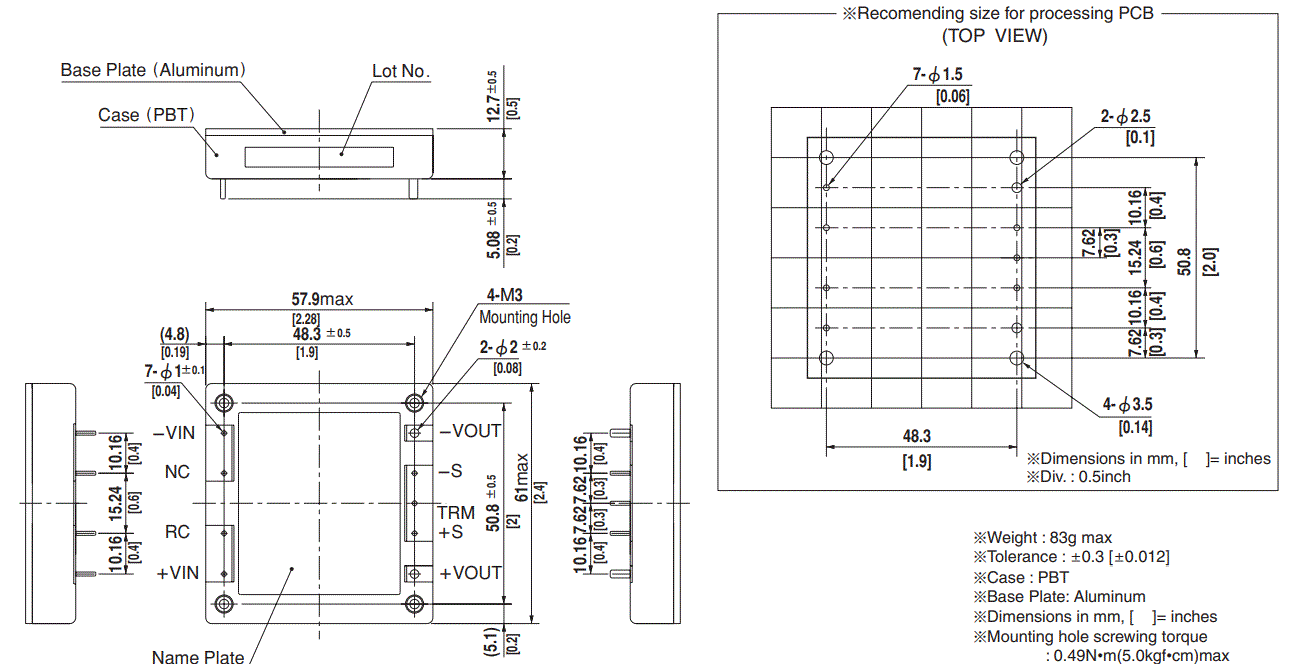
- Weight : 83g max
- Tolerance : t0.3 [t0.012]
- Case : PBT
- Base Plate: Aluminum
- Dimensions in mm, [ ]= inches
- Mounting hole screwing torque
- : 0.49N•m(5.0kgf•cm)max
DC-DC Converters Bus Converter.Power Module Type
CBS450

Ordering information

- Series name
- Single output
- Output wattage
- Input voltage
- Output voltage
- Optional
R : with Remote ON/OFF
Positive logic control
T : with Mounting hole
f3.4 thru
| MODEL | CBS4504824 | CBS4504828 | CBS4504832 |
| MAX OUTPUT WATTAGE[W] | 456 | 448 | 400 |
| DC OUTPUT | 24V 19A | 28V 16A | 32V 12.5A |
SPECIFICATIONS
| MODEL | CBS4504824 | CBS4504828 | CBS4504832 | ||
|
INPUT |
VOLTAGE[V] | DC38 – 60 | DC36 – 76 | DC36 – 76 | |
| CURRENT[A] *1 | 10.6typ | 10.5typ | 9.3typ | ||
| EFFICIENCY[%] *1 | 90typ | 91typ | 91typ | ||
|
OUTPUT |
VOLTAGE[V] | 24 | 28 | 32 | |
| CURRENT[A] | 19 | 16 | 12.5 | ||
| LINE REGULATION[mV] | 48max | 56max | 64max | ||
| LOAD REGULATION[mV] | 48max | 56max | 64max | ||
|
RIPPLE[mVp-p] |
-20to +100C*2 | 180max | 210max | 210max | |
| -40 to -20C*2 | 220max | 260max | 260max | ||
| 0to 15%Load*2 | 360max | 430max | 430max | ||
|
RIPPLE NOISE[mVp-p] |
-20to +100C*2 | 220max | 260max | 260max | |
| -40 to -20C*2 | 280max | 330max | 330max | ||
| 0to 15%Load*2 | 440max | 520max | 520max | ||
| TEMPERATURE REGULATION[mV] | 0 to +65C | 240max | 280max | 280max | |
| -40 to +100C | 480max | 560max | 560max | ||
| DRIFT[mV] *3 | 90max | 90max | 120max | ||
| START-UP TIME[ms] | 200max (DCIN 48V, Io=100%) | ||||
| OUTPUT VOLTAGE ADJUSTMENT RANGE[V] *4 | Fixed (TRM pin open), adjustable by external resistor | ||||
| 19.2 – 26.0 | 16.8 – 32.2 | 25.6 – 35.2 | |||
| OUTPUT VOLTAGE SETTING[V] *1 | 23.52 – 24.48 | 27.44 – 28.56 | 31.36 – 32.64 | ||
|
PROTECTION CIRCUIT AND OTHERS |
OVERCURRENT PROTECTION | Works over 105% of rating and recovers automatically | |||
| OVERVOLTAGE PROTECTION[V] | 27.60 – 33.60 | 32.20 – 39.20 | 36.80 – 44.80 | ||
| REMOTE SENSING | Provided | ||||
| REMOTE ON/OFF | Provided (Negative logic L : ON, H : OFF) | ||||
|
ISOLATION |
INPUT-OUTPUT | DC1,500V or AC1,000V 1minute, Cutoff current = 10mA, DC500V 50MW min(20t15C) | |||
| INPUT-BASE PLATE | DC1,500V or AC1,000V 1minute, Cutoff current = 10mA, DC500V 50MW min(20t15C) | ||||
| OUTPUT-BASE PLATE | AC500V 1minute, Cutoff current = 100mA, DC500V 50MW min (20t15C) | ||||
|
ENVIRONMENT |
OPERATING TEMP.,HUMID.AND ALTITUDE | -40 to +100C (On aluminum base plate), 20 – 95%RH (Non condensing) (Refer to “Derating”), 3,000m (10,000feet) max | |||
| STORAGE TEMP.,HUMID.AND ALTITUDE | -40 to +100C, 20 – 95%RH (Non condensing), 9,000m (30,000feet) max | ||||
| VIBRATION | 10 – 55Hz, 49.0m/s2 (5G), 3minutes period, 60minutes each along X, Y and Z axis | ||||
| IMPACT | 196.1m/s2 (20G), 11ms, once each along X, Y and Z axis | ||||
| SAFETY | AGENCY APPROVALS | UL60950-1, C-UL, EN62368-1 | |||
| OTHERS | CASE SIZE/WEIGHT | 57.9X12.7X61.0mm [2.28X0.5X2.4 inches] (WXHXD) / 83g max | |||
| COOLING METHOD | Conduction cooling (e.g. heat radiation from the aluminum base plate to the attached heat sink) | ||||
- At rated input(DC48V), rated load, and aluminum base plate temperature 25C.
- Ripple and ripple noise is measured by using measuring board with recommended capacitor Co & the film capacitor 0.1mF. Refer to the manual.
- Drift is the change in DC output for an eight hour period after a half-hour warm-up at 25C, with the input voltage held constant at the rated input/output.
- Refer to the manual for the input range.
External view

- Weight : 83g max
- Tolerance : t0.3 [t0.012]
- Case : PBT
- Base Plate: Aluminum
- Dimensions in mm, [ ]= inches
- Mounting hole screwing torque
: 0.49N•m(5.0kgf•cm)max
CBS-series
Pin Configuration
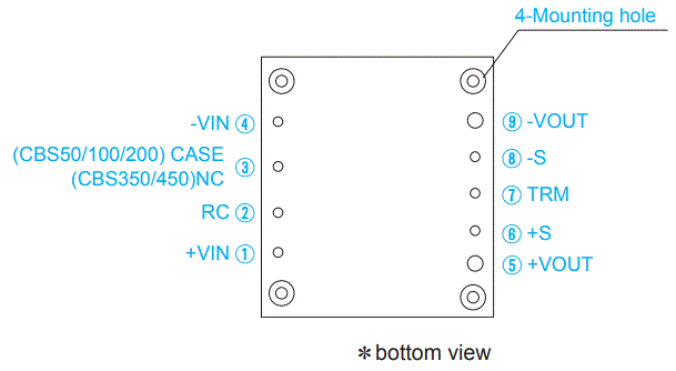
| No. | Pin Name | Function |
| 1 | +VIN | +DC input |
| 2 | RC | Remote ON/OFF |
| 3 | NC | No connection (CBS350/450) |
| CASE | Wiring base plate (CBS50/100/200) | |
| 4 | -VIN | -DC input |
| 5 | +VOUT | +DC output |
| 6 | +S | +Remote sensing |
| 7 | TRM | Adjustment of output voltage |
| 8 | -S | -Remote sensing |
| 9 | -VOUT | -DC output |
| Mounting hole | Mounting hole |
Implementation・Mounting Method
Mounting method
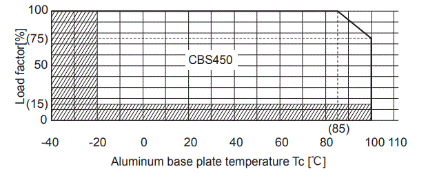
When multiple power modules are used side by side, position them with sufficient spaces to allow adequate air ventilation so that the aluminum base plate temperature of each power module will remain within the temperature range shown in the ‟derating”.
¡Do not pass the DC input pattern underneath the power module as this will increase conducted noise. Place the DC input pattern away from the power module. Do not pass the DC output pattern underneath the power module as this will increase output noise. Place the DC output pattern away from the power module.
High frequency noise is radiated from the power module. When mounting the power module on a PCB, leave a copper pattern on the PCB to let it act as a shield and connect this pattern to the CASE pin (CBS50/100/200) or the mounting hole.
When a heat sink cannot be fixed on the base plate side, order the power module with ”-T”option. A heat sink can be mounted by affixing a M3 tap on the heat sink. In case of CBS350/450, make sure a mounting hole will be connected to a grounding capacitor CY.
| Mounting hole | |
| Standard | M3 tapped |
| Optional : -T | f3.4 thru |
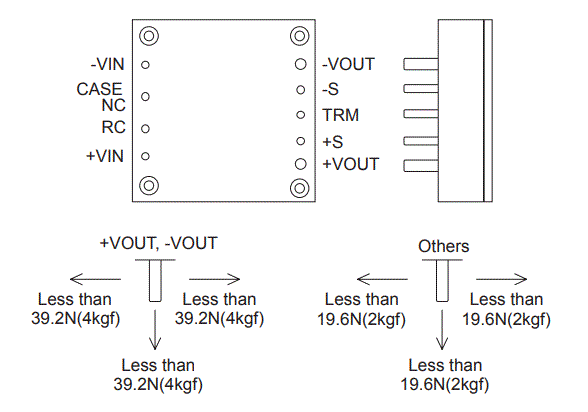
Stress onto the pins
- Applying excessive stress to the input or output pins of the power module may damage internal connections. Avoid applying stress in excess of that shown in right figure.
- Input and output pins are soldered onto the internal PCB. Do not bend or pull the leads with excessive force.
- As unexpected stress may be applied to the pins, set the diameter of the PCB mounting hole at 3.5mm.
- As unexpected stress may be applied to the pins from vibration or shock, fix the power module by using the mounting holes with screws to reduce stress.
- Fix the power module to the PCB with the screws before soldering the input and output pins to prevent the PCB pattern being damaged.
Soldering temperature
- Flow soldering: 260ª for up to 15 seconds.
- Soldering iron (26W) : 450ª for up to 5 seconds.
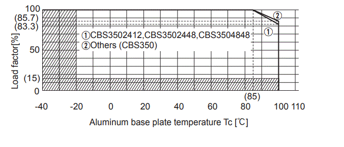
Derating
- Use the power modules with conduction cooling (e.g. heat dissipation from the aluminum base plate to the attached heat sink).Below shows the derating curves with respect to the aluminum base plate temperature. Note that operation within the hatched areas will cause a significant level of ripple and ripple noise. Contact us for more information on cooling methods.
- It is necessary to note thermal fatigue life by power cycle. Please reduce the temperature fluctuation range as much as possible when the up and down of temperature are frequently generated.Contact for more information on cooling methods.
CBS50, CBS100, CBS200

CBS350
CBS400
Instruction Manual
It is neccessary to read the “Instruction Manual” and “Before using our product” before you use our product.
Instruction Manual https://www.cosel.co.jp/redirect/catalog/en/CBS/
Before using our product https://en.cosel.co.jp/technical/caution/index.html

Basic Characteristics
|
Model |
Circuit method |
Switching frequency [kHz] | Input current [A] | Rated input fuse | Inrush current protection | PCB/Pattern | Series/Redundancy
operation availability |
|||
| Material | Single sided | Double sided | Series operation | Redundancy operation | ||||||
| CBS50 | Forward converter | 310 |
Refer to table No.1 |
– | – | Aluminum | Yes | Yes | *1 | |
| CBS100 | Forward converter | 370 | – | – | Aluminum | Yes | Yes | *1 | ||
| CBS200 | Forward converter | 370 | – | – | Aluminum | Yes | Yes | *1 | ||
| CBS350 | Forward converter | 370 | – | – | Aluminum | Yes | Yes | *1 | ||
| CBS450 | Forward converter | 370 | – | – | Aluminum | Yes | Yes | *1 | ||
Refer to Instruction Manual.
Table1. The value of input current (at rated input voltage and rated load)
|
Model |
Output Voltage | |||||||||
| 1.8V | 2.5V | 3.3V | 5V | 12V | 15V | 24V | 28V | 32V | 48V | |
| CBS5024 | 1.2 | 1.6 | 2.0 | 2.5 | 2.4 | 2.4 | 2.4 | 2.4 | – | – |
| CBS5048 | 0.6 | 0.8 | 1.0 | 1.3 | 1.2 | 1.2 | 1.2 | 1.2 | – | – |
| CBS10024 | 2.5 | 3.2 | 4.1 | 5.0 | 4.8 | 4.8 | 4.8 | 4.8 | – | – |
| CBS10048 | 1.2 | 1.6 | 2.0 | 2.5 | 2.4 | 2.4 | 2.4 | 2.4 | – | – |
| CBS20024 | 3.8 | 4.8 | 6.1 | 7.6 | 9.6 | 9.6 | 9.7 | 9.7 | – | – |
| CBS20048 | 1.9 | 2.4 | 3.0 | 3.8 | 4.8 | 4.8 | 4.8 | 4.8 | – | 4.8 |
| CBS35024 | – | – | – | – | 15 | – | 17 | 17 | 17 | 14 |
| CBS35048 | – | – | – | – | 8.4 | – | 8.2 | 8.1 | 8.2 | 8.2 |
| CBS45048 | – | – | – | – | – | – | 10.6 | 10.5 | 9.3 | – |
Documents / Resources
 |
Cosel CBS-series Converters Bus Converter Power Module Type [pdf] Owner's Manual CBS-series Converters Bus Converter Power Module Type, CBS-series, Converters Bus Converter Power Module Type, Converter Power Module Type, Power Module Type, Module Type |
