COMMSCOPE TC-01001504-IP Flex Frame Optical Distribution Frames

Specifications
Mounting Space: 760258507 ODF-FF19CM-24RU 24 Rack Units
Dimensions (H x W x D): 84.0 x 30.0 x 24.0 in. (213.4 x 133.9 x 60.95 cm)
Weight: 400 lbs. (181.4 Kg); packaged weight 630 lbs. (285.8 Kg)
Product Description
Introduction
This user manual describes the Flex Frame-S and provides directions for installation. Procedures include: unpacking the frame, mounting the frame on a concrete floor or raised floor, and grounding the frame. This user manual lists related publications and how to obtain technical assistance.
Related Publications
The following related publication is available at https://www.commscope.com/SupportCenter
- Propel User Manual (TC-96307-IP) — Manual listed only has info on the Propel panel not the frame) https://www.commscope.com/globalassets/digizuite/944022-tc-96307-ip.pdf
General Description
The Flex Frame-S (760258507 ODF-FFS19CM-24RU) shown in Figure 1, is an optical distribution frame providing a connection point between facility cables in a data center. Facility cables can be high-fiber-count cables containing rollable ribbons, and of a type suitable for being routed indoors or outdoors. The basic product consists of a 19-inch seismic rack with multiple cable managers, at the bottom of the frame. The Flex Frame-S has 24 rack units for fiber connector panel, slack storage not and multiple cable managers. The Flex Frame-S has removable front doors at the bottom that are used to cover the fiber jumper slack storage area. The doors can be permanently removed if desired as well.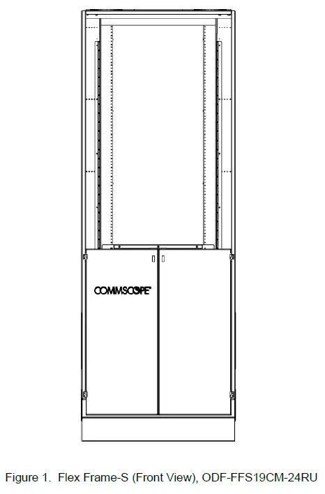
Figure 2 shows the frame in rear isometric and front views with call outs indicating important features of the frame.
The identified features include the following:
- 19-Inch Seismic Rack yields basic rack and front view structure of the Flex Frame-S.
- Flat Clamp Bracket is used to secure cables at the top of the frame.

Dimensions and Specifications
The Flex Frame-S has a mounting space of 24 rack units with dimensions of 84.0 x 30.0 x 24.0 inches and a weight of 400 lbs. Figure 3 shows the Flex Frame-S dimensions.

Unpacking and Inspection
The Flex Frame-S is shipped on a pallet within box Figure 4.. Use the following procedure to inspect and unpack the items on the box.
- Using a fork lift, move the pallet to the installation location within your facility.
- Inspect the exterior of the shipping container(s) for evidence of rough handling that may have damaged the components in box. If damage is detected or if parts are missing, file a claim with the commercial carrier and notify CommScope Support Center at http://www.commscope.com/SupportCenter
 Note: Save all shipping containers for use if the equipment requires shipment at a future date. (if required)
 - Carefully unpack the items on the pallet identifying the following:
- Box containing hardware
Installation
General
The Flex Frame-S can be installed on a concrete floor or raised floor. Information is provided in separate sections for each scenario. Other steps are the same for concrete floor and raised floor installations.
Overview of Installation
The Flex Frame-S can be installed on a concrete floor or raised floor.
Installation involves the following main steps:
- The frame, while still on the pallet, is moved to the installation location.
- The installation template (Isolation PAD) is used to mark the frame footprint on the floor.
- The frame is mounted on a concrete floor or raised floor.
Note: Raised floor Installation kit must be separately ordered.
- Frame is grounded.
- The total assembly is final checked to ensure everything is in correct order.
Required Tools and Material
The following tools are required for installing the Flex Frame-S.
- Slot tip and Phillips screwdrivers – #1, #2, #3
- Level
- Socket wrench
- Set of sockets – 0.25 to 1 inch (8 to 25.4 mm)
- Set of open-end/box-end wrenches – 0.25 to 1 inch (8 to 25.4 mm)
- T7 Torx bit
- Drill with metal and concrete drill bits – 0.25 to 1 inch (8 to 25.4 mm)
- Ruler or tape measure
- Torque wrench – 19.9 ft-lbs. (27 Nm)
- Hammer
- Vacuum
- Concrete floor anchors or raised floor kit
- Scissors
Footprint and Installation Template
Figure 5 shows the Flex Frame-S installation template with dimensions of footprint,

Mounting the Frame on a Concrete Floor
To mount the frame on a concrete floor, use the following procedure.
- Determine the frame location and ensure that the front and rear aisles at that location meet the recommended minimum widths shown in Figure 6. Mark the location with the installation template, as shown.

- Place the installation template on the concrete floor at the location just chosen, and use it to mark the concrete for the four mounting holes as shown in Figure 7.

- Set aside the installation template and drill four mounting holes in the concrete at the marks just made, as shown in Figure 8.

- Thread the washer and torque nuts onto the threaded rod, as shown in Figure 9. Insert the anchor bolt assembly into the hole. The washer should touch the top of the anchor sleeve. Tap the anchor bolt assembly with a hammer until the washer touches the concrete.

- Pre-torque the anchor bolt to approximately 30 foot-pounds (41 Newton meters). Refer to Figure 10.

- Loosen the torque nuts several turns, and then remove the torque nut and washer, as shown in Figure 11.
Footprint and Installation Template
Use the provided template to mark the position for mounting the frame.
Mounting the Frame on a Concrete Floor
Securely attach the frame to the concrete floor using appropriate anchors and hardware.
Mounting the Frame on a Raised Floor
If mounting on a raised floor, follow instructions for proper installation to ensure stability.
- The Flex Frame-S can be mounted on a raised floor using the CommScope Raised Floor Mounting Kit, 5/8” (FDF-ACC146). Figure 12 shows an exploded view of the kit components. To order the kit, refer to the following URL: https://www.commscope.com/product-type/cabinets-panels-enclosures/frames-rackscabinets/accessories/itemfdf-acc146/


Grounding Frame
Figure 14 shows the location of the #10-32 ground studs on the front of the Flex Frame-S. The studs are intended for a ground strap with a 2-hole lug with 5/8-inch hole spacing. Ground with AWG wire conforming to local standards.

Contact Information
For technical assistance or inquiries, contact CommScope Support Center at http://www.commscope.com/SupportCenter
- To find out more about CommScope® products, visit us on the web at www.commscope.com
- For technical assistance, customer service, or to report any missing/damaged parts, visit us at http://www.commscope.com/SupportCenter
FAQ
Q: Can the Flex Frame-S be disassembled for relocation?
A: Yes, the frame can be disassembled for relocation if needed. Follow the reverse process of installation.
Q: What is the maximum weight capacity of the Flex Frame-S?
A: The frame has a weight capacity of 400 lbs when properly installed and secured.
Documents / Resources
 |
COMMSCOPE TC-01001504-IP Flex Frame Optical Distribution Frames [pdf] Owner's Manual TC-01001504-IP Flex Frame Optical Distribution Frames, TC-01001504-IP, Flex Frame Optical Distribution Frames, Optical Distribution Frames, Distribution Frames, Frames |