COMET T5540 CO2 Transmitters Web Sensor
PRODUCT DESCRIPTION
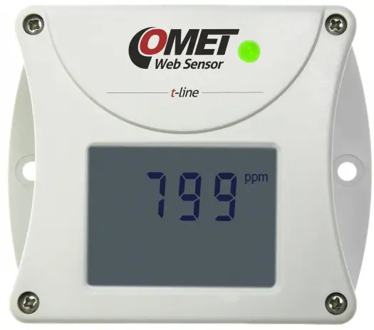
CO2 transmitters Web Sensor T554x and T654x with Ethernet interface are designed for measurement of temperature and relative humidity of air and for measurement of CO2 concentration in air. Transmitters can be used in a chemically non-aggressive environment.
The CO2 concentration is measured using the dual wavelength NDIR sensor with the multipoint calibration. This principle compensates aging of the sensing elements and offers maintenance free operation and outstanding long term stability.
Relative humidity transmitters allows to determine other calculated humidity variables like dew point temperature, absolute humidity, specific humidity, mixing ratio and specific enthalpy.
Measured and calculated values are displayed on a two-line LCD display or can be read and then processed via Ethernet interface. The device is also equipped with three-color LED for visual indication of the CO2 concentration. The following formats of Ethernet communication are supported: www pages and protocols Modbus TCP, SNMPv1, SOAP, XML and JSON. The transmitter may send also a warning message if the measured value exceeds adjusted limit. The messages can be sent up to 3 e-mail addresses or to Syslog server and can be sent by SNMP Trap too. The alarm states are also displayed on the websites. The device setup can be made by the Tensor software (free of charge at www.cometsystem.com) or using the www interface.
| type * | measured values | construction | mounting |
| T5540 | CO2 | ambient air | wall |
| T6540 | T + RH + CO2 + CV | ambient air | wall |
| T5541 | CO2 | probe on cable | wall |
| T6541 | T + RH + CO2 + CV | probes on cable | wall |
| T5545 | CO2 | duct mount | fix by means of the cable gland |
| T6545 | T + RH + CO2 + CV | duct mount | fix by means of the cable gland |
* models marked TxxxxZ are custom – specified devices.
T…temperature, RH…relative humidity, CO2…concentration CO2 in air, CV…computed values.
INSTALATION AND OPERATION
The transmitters T5540 (T6540) and T5541 (T6541) fasten on a flat surface with two screws or bolts. The external CO2 probe unpack and connect to the T5541 (T6541) device. Place the external probes into the measured area. The T5545 (T6545) transmitter install by inserting the metal stem into the Pg21 cable gland so that the measured air was fed into the head of device (see Technical specification). To fasten the stem it is also possible to use the flange PP4 (optional accessory). Pay attention to the location of the device and probes. Incorrect selection of working position could adversely affect accuracy and long-term stability of measured value. Devices don’t require special maintenance. We recommend that you regularly verify the accuracy of the measurement with calibration.
DEVICE SETUP
For network device connection it is necessary to know new suitable IP address. The device can obtain this address automatically from a DHCP server or you can use the static IP address, which you can get from your network administrator. Install the latest version of Tensor software to your PC and according to the “Device connection procedure” (see next page) you connect the Ethernet cable and power supply adapter. Then you run Tensor program, set the new IP address, configure the device in accordance with your requirements (alarm conditions, limits of CO2 LED indication, sending of e-mail) and finally store the settings. The device setup can be made by the web interface too (see manual for devices at www.cometsystem.com ).
After device switching on starts internal test. During this time (about 20 s) LCD display shows ![]() instead value of CO2 concentration.
instead value of CO2 concentration.
The IP address of each device is set by the manufacturer to 192.168.1.213.
ERROR STATES
Device continuously checks its state during operation and if an error appears, it is displayed relevant code: Err 1 – measured value (except of CO2 concentration) or calculated value is over the upper limit, Err 2 – measured or calculated value is below the lower limit or concentration CO2 measurement error occurred, Err 0, Err 3 and Err 4 – it is a serious error, please contact distributor of the device (for devices with an external probe CO2G-10 the Err 4 indicates that the probe is not connected).
SAFETY INSTRUCTIONS
![]()
- Don´t use and don’t store the devices without the cover of the temperature and humidity sensors.
- It is not recommended to use the humidity transmitters for long time under condensation conditions.
- Take care when unscrewing the filter cap as the sensor element could be damaged.
- Use only the power adapter according to technical specifications and approved according to relevant standards.
- Don’t connect or disconnect transmitters while power supply voltage is on.
- Installation, electrical connection and commissioning should be performed by qualified personnel only.
- Devices contain electronic components, it needs to liquidate them according to legal requirements.
- To complement the information in this data sheet read the manuals and other documentation, which are available in the Download section for a particular device at www.cometsystem.com.
TECHNICAL SPECIFICATIONS
| Device type | T5540 | T6540 | T5541 | T6541 | T5545 | T6545 |
| Supply voltage – coaxial connector, diameter 5.1 * 2.1mm | 9-30Vdc | 9-30Vdc | 9-30Vdc | 9-30Vdc | 9-30Vdc | 9-30Vdc |
| Power consumption | 1W | 1W | 1W | 1W | 1W | 1W |
| Max. power consumption (for 50 MS with 15 s period) | 4W | 4W | 4W | 4W | 4W | 4W |
| Temperature measuring range | – | – 30 to + 80 °C | – | -30 to +105 °C | – | -30 to +60 °C |
| Accuracy of temperature measurement | – | ± 0.6 °C | – | ± 0.4°C | – | ±0.4°C |
| Relative humidity (RH) measuring range (no condensation) * | – | 0 to 100%AH | – | o to 100 %RH | – | 0 to 100 %RH |
| Accuracy of humidity measurement from 5 to 95%RH at 23 °C | – | ± 2.5%RH | – | ± 2.5 %RH | – | ± 2.5%RH |
| CO2 concentration measuring range ** | 0 to 5000 ppm | 0 to 5000 pam | 0 to 10000 ppm | 0 to 10000 ppm | 0to 5000 ppm | 0 to 5000 ppm |
| Accuracy of CO2 measurement at 25 °C and 1013 hPa | ± (50ppm ±3% of measured value) | ± (50ppm+3% of measured value) | ± (100ppm+5% of measured value) | ± (100ppm+5% of measured value) | ± (50ppm+3% of measured value) | ± (50ppm+3% of measured value) |
| Calculated humidity variables – dew point temperature,…. | – | yes | – | yes | – | yes |
| Recommended calibration interval of the device *** | 5 years | 1 year | 5 years | 1 year | 5 years | 1 year |
| Protection class – case with electronics | IP30 | IP30 | IP30 | IP30 | IP30 | IP30 |
| Protection class – measuring end of stem / CO2 probe / RH probe | -/-/- | IP40/-/- | -/IP65/- | -/IP65/IP40 | IP20/-/- | IP20 /-/- |
| Temperature operating range of the case with electronics **** | – 30to + 60 °C | -30 to 60 °C | -30 to+80 °C | -30 +80 °C | -30 to +60 °C | -30 to +60 °C |
| Temperature operating range of the measuring end of stem | – | -30 to 80 °C | – | – | – | -30 to +60 °C |
| Temperature operating range of the C*O_{2} ext. probe (moving less cable) | – | – | -25 +60°C | -25 to +60 °C | – | – |
| Temperature operating range of the RH + T external probe | – | – | – | -30 to +105°C | – | – |
| Humidity operating range | 5 to 95%RH | 5 to 95%RH | 0 to 100%RH | 0 to 100%RH | 5 to 95%RH | 5 to 95%RH |
| Mounting position | connectors upwards | sensor cover downwards | any position | any position | any position # | any position # |
| Storage temperature range (5 to 95%RH no condensation) | -40 to +60 °C | -40 to +60 °C | -40 to +60 °C | -40 to +60 °C | -40 to +60 °C | -40 to +60 °C |
| Electromagnetic compatibility according to | EN 61326-1 EN 55011 | EN 61326-1 EN 55011 | EN 61326-1 EN 55011 | EN 61326-1 EN 55011 | EN 61326-1 EN 55011 | EN 61326-1 EN 55011 |
| Weight | 140 g | 160 g | 240 (270,330) g | 320 (300, 530) g | 280 g | 280 g |
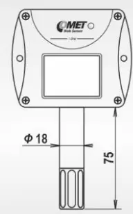
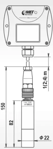
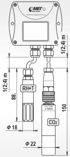
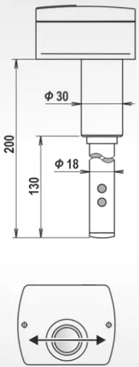
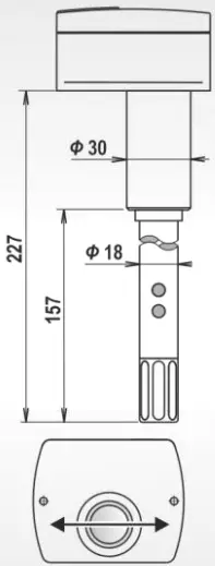
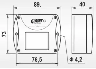
| Dimensions [mm] | 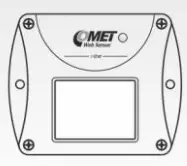 |
 |
 |
 |
 #air flow direction |
 # air flow direction |
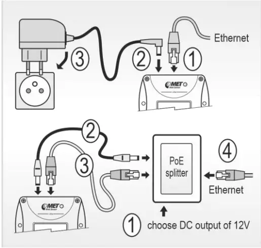
| Device connection procedure
|
 |
|||||
- The relative humidity measuring range is limited at temperatures above 85°C, see manuals for devices.
- LED indication (preset by manufacturer): green (0 to 1000 ppm), yellow (1000 to 1200 ppm), red (1200 to 5000/10000 ppm).
- Recomended calibration intervals: relative humidity – 1 year, temperature – 2 years, CO2-5 years.
- It is recommended to switch off the LCD display at ambient temperature above 70°C.
COMET SYSTEM, s.r.o., Bezrucova 2901.
756 61 Roznov pod Radhostem, Czech Republic.
Specifications are subject to change without notice.
February 2025 / ie-snc-n-t5(6)5xx-09.
![]()
Documents / Resources
 |
COMET T5540 CO2 Transmitters Web Sensor [pdf] User Guide T5540, T6540, T5541, T6541, T5545, T6545, T5540 CO2 Transmitters Web Sensor, T5540, CO2 Transmitters Web Sensor, Transmitters Web Sensor, Web Sensor, Sensor |