Comba MRU1000 Distributed Remote Unit RF Unit

Specifications
- Networking: FHD 4
- Service Capability: Support 2x 100MHz 4T4R cell, 400 active users, and 1200 RRC connected users in each cell
- Synchronization Size: Not specified
- Weight: 7.2kg
- Power Supply: Support AC100V-240V or DC: -48V (-40~-57v)
- Power Consumption: Not specified
Product Usage Instructions
- Safety and Security
- Ensure to follow all safety guidelines mentioned in the user manual to prevent any accidents or damage during installation and operation.
- System Introduction
- 5G Access Unit
- The 5G access unit is a key component of the system. Follow the provided technical specifications for proper setup and operation.
- Installation
- Refer to Section 3 of the user manual for detailed equipment installation instructions.
- Commissioning
- Follow the steps outlined in Section 4 for site commissioning, including configuring WAN networks and other necessary parameters.
- 5G Access Unit
FAQs
- Q: What should I do if I encounter issues during commissioning?
- A: If you encounter any problems during commissioning, refer to the troubleshooting section of the user manual or contact customer support for assistance.
- Q: Can the 5G access unit support multiple network slices?
- A: Yes, the 5G access unit supports multiple network slices as defined by the core network. Ensure to configure them properly based on your requirements.
Comba Distributed gNB User Manual
Comba Distributed gNB User Manual
Proprietary & Confidential 2023 Comba
Proprietary & Confidential 2023 Comba
Comba Distributed gNB User Manual
This device complies with Part 15 of the FCC Rules. Operation is subject to the following two conditions: (1) this device may not cause harmful interference, and (2) this device must accept any interference received, including interference that may cause undesired operation. This is NOT a CONSUMER device. It is designed for installation by FCC LICENSEES and QUALIFIED INSTALLERS. You MUST have an FCC LICENSE or express consent of an FCC Licensee to operate this device. Unauthorized use may result in significant forfeiture penalties, including penalties in excess of $100,000 for each continuing violation.
Safety and Security
1) When installing the equipment, please leave enough space for heat dissipation, and keep away from heat source or fire, such as electric heater, candle, etc; 2) Do not disassemble the equipment by yourself. In case of equipment failure, please contact the equipment supplier. 3) It must be kept dry during storage, transportation and use. If liquid accidentally flows into the chassis, please cut off the power immediately and contact the equipment supplier. 4) If there are the following phenomena: smoke, abnormal sound, strong smell, etc., please stop using immediately and unplug the power plug; 5) Do not let children use the equipment alone without supervision, and prohibit children from playing with the equipment and accessories to avoid accidents. 6) Please install the equipment on a stable and solid wall, and the environment shall be dry, ventilated and free from strong light 7) Please keep the power plug clean and dry to avoid electric leakage. Do not use damaged or aged power cable 8) Do not place any objects on the power cord or power plug of the equipment, and do not cover chassis with objects. Before cleaning the equipment, please turn off the equipment and cut off the power supply. When cleaning, do not clean with corrosive detergent, but wipe with a soft dry cloth
Proprietary & Confidential 2023 Comba
Comba Distributed gNB User Manual
System Introduction
2.1 5G Access Unit
The appearance of 5G access unit is shown in Figure 2-1 Appearance of 5G Access Unit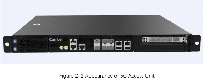
Figure 2-1 Appearance of 5G Access Unit
The technical specification of 5G access unit are shown in Table 2-1 Key technical specification
Table 2-1 Key technical specification
Item
Performance and specifications
Networking
FHD 4
Service capability
Support 2x 100MHz 4T4R cell
Support 400 active users and 1200 RRC connected users in each cell;
Synchronization Size
Support GPS, 1588v2 clock synchronization 19 “standard rack, height 1U. 440 mm × 410 mm × 42mm (w × D × h)
Weight
7.2kg
Power supply
Support AC100V-240V or DC: – 48V (- 40~-57v)
Power Consumption
<200W
Environmental protection IP30
Installation method
Rack or wall mounted
Cooling Operation temperature
FAN -5+55
Operation relative humidity 15% – 85% (no condensation)
The interface identification of 5g access unit panel is shown in Figure 2-2 Interface of access unit
Proprietary & Confidential 2023 Comba
Comba Distributed gNB User Manual
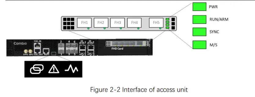
Figure 2-2 Interface of access unit
The interface description of 5g access unit is shown in Table 2-2 Access unit interface
description
Table 2-2 Access unit interface description
Interface
Interface description and function description
OP1, OP2
25G SFP + Optical , Backhaul Port, Reserved
OP3, OP5, OP6
10G SFP + Optical , Backhaul Port, reserved
OP4
10G SFP + Optical , Backhaul Port
LAN1
1GE, LMT interface, 100M/1000M
LAN2
1GE, BMC Debug, reserved
USB1/USB2
2 x USB3.0 interface for connecting mouse / keyboard / USB device, etc
GPS
GPS interface (SMA),
1PPS
1 PPS second pulse input
RGPS
RGPS interface (RJ45)
ToD_ IN
1PPS+ToD second pulse input
ToD_ OUT FHD Card
1PPS+ToD second pulse output 4 × 12.5Gbps SFP + optical interface, star connection with extension unit,
FH1~FH4
supporting CPRI.
FHD Card
12.5Gbps SFP + optical interface, equipment cascading.
FH5
5G AU LED indicator is shown in Table 2-3 5G AU LED Indicator
Table 2-3 5G AU LED Indicator
Identification
Function
Color
Status
PWR
Power indicator Green
On
Off
OP1~6
SFP Synchronous Green
Green On
indicator
/Orange
Orange On
Orange Flashing Off
Description Power supply normal Power supply abnormal Link OK
SFP exists. Optical module receiving or sending abnormality. Bit error or the link is out of lock Network not connected or
Proprietary & Confidential 2023 Comba
Comba Distributed gNB User Manual
LAN1~2
SYNC FHD Card PWR FHD Card RUN/ARM
FHD Card SYNC FHD Card M/S
LAN indicator
Orange
Green SYNC indicator Green
Power indicator Green
Run/Alarm indicator
Green /Orange
SYNC indicator Green
Master/Slavery indicator
Green
SFP not exists
On
Link normal without data
transmission
Flashing
Link normal with data
transmission
Off
Link not connected
On
Link Up 1000Mbps
Off
Link Up 100Mbps or Link
Not Up
On
Sync success
Flash
Sync source exists but fail to
sync
Off
Sync source not exists
On
Power normal status
Off
Power abnormal status
Green On
Software not running
Green
Slow Equipment normal status
Flashing
Green
Fast Equipment powering up or
Flashing
software upgrading
Orange On
Normal alarm
Orange Flashing Serious alarm
Off
Power off or hardware fault
On
Sync success
Flashing
Sync source exists but fail to
sync
Off
Sync source not exists
On
Board running as master
Off
Board running as slavery
2.2 Remote Radio Unit
The appearance of the Remote Radio Unit Remote Radio Unit (RRU) is shown in Figure 2-3 Appearance of
Proprietary & Confidential 2023 Comba
Comba Distributed gNB User Manual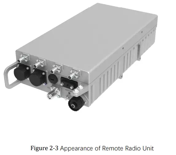
Figure 2-3 Appearance of Remote Radio Unit Key technical specification of Remote Radio Unit are shown in Table 2-4 Key technical
specification.
Table 2-4 Key technical specification
Radio Specification Technology TRx Configuration Operation Bandwidth Instantaneous Bandwidth Occupied Bandwidth Capacity (per antenna port) Operating Frequency Interface to BBU Output Power per Tx ACLR Transmitter Spurious Emissions EVM Noise Figure Blocking Features Receiver spurious emissions
Interface
NR
ANT1-4 OPT1-2 Power
NR 4T4R 150MHz 100MHz 100MHz
1 carriers 3550 3700MHz
CPRI 10W Compliant with 3GPP TS 38.104 Compliant with 3GPP TS 38.104 Compliant with 3GPP TS 38.104 Typical: 3.5dB Compliant with 3GPP TS 38.104 Compliant with 3GPP TS 38.104
4 x 4.3-10 Female 2 x SFP+
AC100-240V
Proprietary & Confidential 2023 Comba
Comba Distributed gNB User Manual
AISG
Debug
GPS
PWR
RUN/ALM
LED Indicator
ACT VSWR
OP1
OP2
lectrical and Mechanical Specification
Volume
Power Supply
Power Consumption
Weight
Humidity
Operating Temperature
IP Rating
Mounting Options
AISG 2.0 Mini-USB (Ethernet over Mini-USB via LMT cable) Optional, N-Type Female, GPS Bands customized
Power Running Status System Running Status
PA Running Status RF Channel VSWR Checking Status
Optical Link Status Optical Link Status
370mm*200mm*95mm
100-240 VAC/47-63Hz Max: 180W* 7kg 5% ~95% -40°C ~+55°C IP65
Pole (45mm to 120mm) / Wall
Note: * The max power consumption of an RRU is measured at 25°C ambient
temperature. The actual power consumption may have a 10% deviation from the
value.
Proprietary & Confidential 2023 Comba
Comba Distributed gNB User Manual
Proprietary & Confidential 2023 Comba
Comba Distributed gNB User Manual
Equipment installation
3.1 5G AU installation
3.1.1 Tool requi rements
Requirements for installation tools are shown in Table 3-1 Requirements for installation
tools.
Table 3-1 Requirements for installation tools
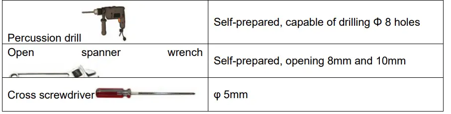
Tool type
Function
Percussion drill
Open
spanner
Self-prepared, capable of drilling 8 holes wrench
Self-prepared, opening 8mm and 10mm
Cross screwdriver
5mm
3.1.2 Wall-mounted installation
Step 1: Take the AU out of the package, and adjust the installation direction of the lug according to the figure, as shown in Figure 3-1 Installation Diagram of Case Lug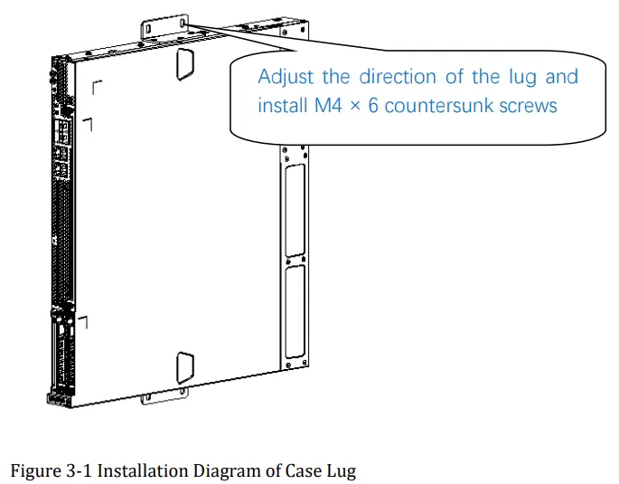
Adjust the direction of the lug and install M4 × 6 countersunk screws
Figure 3-1 Installation Diagram of Case Lug Step 2: Punch four 8 holes in the wall as shown in Figure 3-2 AU wall installation drilling dimension. The hole depth is 50-60mm. Fix the expansion bolt on the wall to ensure the
Proprietary & Confidential 2023 Comba
Comba Distributed gNB User Manual installation is firm. Take out the nut and gasket of the expansion bolt, and align the installation hole of the AU lug with the expansion bolt, as shown in Figure 3-3 AU wall installation diagram.
Figure 3-2 AU wall installation drilling dimension
Figure 3-3 AU wall installation diagram
Proprietary & Confidential 2023 Comba
Comba Distributed gNB User Manual
Step 3: install the flat cushion and nut, tighten the nut with a fixed open-ended wrench, and the installation is completed.
3.1.3 Cabinet installation – tray installation (applicable to 1000mm cabinet)
9) Installation tools
Installation tools are shown in Table
Table 3-2 Installation Tools
Name
Remarks
Cross screwdriver (universal type) Self-prepared, 5mm
10) Equipment installation
Step 1: Take the AU equipment out of the package and install the lug for the installation of the supporting tray on the AU, as shown in Figure 3-4 Installation diagram of hanger for cabinet.
Figure 3-4 Installation diagram of hanger for cabinet Step 2: Install the tray on the cabinet, as shown in Figure 3-5 Tray Installation Diagram.
Adjust the position of the tray, 2 M6× 16 pan-head combination screw for each tray fixation
Figure 3-5 Tray Installation Diagram Step 3: insert the AU horizontally into the cabinet, tighten the M6 screws, as shown in Figure 3-6 Installation diagram of AU on cabinet, and the installation is completed.
Proprietary & Confidential 2023 Comba
Comba Distributed gNB User Manual
Figure 3-6 Installation diagram of AU on cabinet 3.1.4 Cabinet installation – rail installation (applicable to cabinets 600mm to
1000mm deep)
1) Installation tools
Installation tools are shown in Table 3-3 Installation Tools.
Table 3-3 Installation Tools
Name
Remarks
Cross screwdriver (universal type) Self-prepared, 5mm
2) Equipment installation
Step 1: Take the AU equipment out of the package and install the hanger for the installation of the supporting guide rail on the AU, as shown in Figure 3-7 Installation diagram of hanger for guide rail.
Adjust the direction of the hanger and install M4 × 6 countersunk screw
Figure 3-7 Installation diagram of hanger for guide rail
Step 2: Install the sliding rail on the cabinet, as shown in Figure 3-8 to Figure 3-11. 1. Take out the sliding guide rail and remove the screws on the guide rail, a total of 5, as
shown in Figure 3-8
Proprietary & Confidential 2023 Comba
Comba Distributed gNB User Manual
Take out the guide rail and remove the front and rear screws on the guide rail, a total of 5. Figure 3-8 2. Install the sliding guide rail on the cabinet, as shown in Figure 3-9 Schematic diagram of sliding guide rail installed on the cabinet
Figure 3-9 Schematic diagram of sliding guide rail installed on the cabinet 3. Repeat the steps of (1) and (2) above to install the sliding rails on the other side on the
cabinet frame. Pay attention to the horizontal alignment of the sliding rails on both sides.
Figure 3-10
Align the guide pins on both sides of the AU with the guide slot of the sliding rail, and push the AU into the cabinet along the rail.
Proprietary & Confidential 2023 Comba
Comba Distributed gNB User Manual
After pushing the AU to the bottom along the guide rail, lock the two loose screws on the AU and complete the installation.
Figure 3-11
3.1.5 Installation of ground wire
3.1.5.1 GPS grounding Take the yellow and green grounding wire of 2 m from the accessories of the whole machine, cut the yellow and green bottom wire of about 1 m from the bare wire end, and strip the bare wire of 4 cm and 1 cm from the two ends respectively. Refer to Figure 3-12 Schematic diagram of grounding wire stripping
Figure 3-12 Schematic diagram of grounding wire stripping Take out an OT2.5-6 terminal from the accessories of the whole machine, insert the 1cm long end into the grounding terminal hole, and press it tightly with pliers. Refer to Figure 3-13 Schematic diagram of terminal crimping for terminal crimping diagram.
Figure 3-13 Schematic diagram of terminal crimping Use a heat-shrinkable tube with a diameter of 6cm to cover the ground wire, and thread the 4cm long bare wire into the grounding copper wire of the arrester. First, wrap it tightly and then press it with pliers, and then weld it with soldering iron as much as possible, as shown in Figure 3-14 Grounding wire connection. Put the heat-shrinkable tube at the junction, and then heat it to cover the terminal, as shown in Figure 3-15 Heat shrinkable tube protection.
Proprietary & Confidential 2023 Comba
Comba Distributed gNB User Manual
Figure 3-14 Grounding wire connection
Figure 3-15 Heat shrinkable tube protection As shown in Figure 3-16 Wiring reference diagram, the GPS grounding wiring is connected to the ground through GPS surge protector. Pay attention to the fixation of the ground wire to avoid contact with other lines.
Figure 3-16 Wiring reference diagram 3.1.5.2 AU chassis grounding Take a yellow and green ground wire, cut the corresponding length according to the actual wiring requirements, and make it as short as possible. The grounding terminal is connected to the chassis grounding port, and the other end is connected to the cabinet ground wire, as shown in Figure Figure 3-17 Installation diagram of AU chassis grounding wire
Proprietary & Confidential 2023 Comba
Comba Distributed gNB User Manual Figure 3-17 Installation diagram of AU chassis grounding wire
Proprietary & Confidential 2023 Comba
Comba Distributed gNB User Manual
Proprietary & Confidential 2023 Comba
Comba Distributed gNB User Manual
Proprietary & Confidential 2023 Comba
Comba Distributed gNB User Manual
3.1.6 Equipment power The AU and expansion unit need 220V AC power supply, and the power supply mode is preferred to adopt the power supply mode of power cable cutting. This power supply mode needs to take single-phase power (220V AC) from the three-phase power in the distribution cabinet. The schematic diagram of power supply is shown in !.
Figure 3-18Schematic diagram of equipment power cable cut off and power taken from cabinet If the site does not have the power cable cut-out method, use the socket to take 220V AC power. The power socket must be at a height that can not be easily reached by ordinary people to prevent people from unplugging the power plug of the base station.
3.2 Remote Radio Unit installation
3.2.1 Warning for Remote Radio Unit Warning! Any installation, adjustment, maintenance and repair of the equipment must only be carried out by trained, authorized personnel. At all times, personnel must comply with any safety notices and instructions.
Proprietary & Confidential 2023 Comba
Comba Distributed gNB User Manual
3.2.2 Installation Requirements
3.2.2.1 Installation Location Mounting surface shall be capable of supporting the weight of the equipment. In order to avoid electromagnetic interference, a proper mounting location must be selected to minimize interference from electromagnetic sources such as large electrical equipment. 3.2.2.2 Environmental Humidity has an adverse effect on the reliability of the equipment. It is recommended to install the equipment in locations having stable temperature and unrestricted air-flow. The installation location for the system should be well ventilated. The equipment has been designed to operate at the temperature range and humidity level as stated in the product specifications at temperatures ranging from -40~55oC and a relative humidity of maximum 95%. 3.2.2.3 Powering
To ensure the stability and safety of the power supply, it is recommended that the device operate on a dedicated AC circuit breaker or fuse. This approach helps to isolate the device from other electrical loads, reducing the risk of power fluctuations and ensuring a stable power supply for the device.
3.2.2.4Grounding Requirement Verify that the equipment has been well grounded. This includes radio remote unit, external combiner, antennas and all cables connected to the system. Ensure lightning protection for the antennas is properly grounded.
3.2.2.5 Cable Routing Ensure all cables, e.g. power cable, feeder cable, optic fiber, commissioning cable, connecting are properly routed (use drip-loops) and secured so that they are not damaged. Fiber optic cables require proper handling. Do not stretch, puncture, or crush the fiber cable(s) with staples, heavy equipment, doors, etc. Always maintain the minimum bending radius specified by the cable manufacturer. The minimum bend radius is usually ten times the cable’s outer diameter. In the case of single optical fiber that is not in a cable, the minimum bending radius to be observed is 30 mm. Wave division multiplexing (WDM) units require single-mode fiber Use minimum splicing/connectors to achieve minimum losses on the fibers. Use precaution while installing, bending, or connecting fiber optic cables. Use an optical power meter and OTDR for checking the fiber optic cables. Make sure the environment is clean while connecting/splicing fiber optic cables. All fiber optic connections should be cleaned prior to attaching to termination points using a dry cleaning device (i.e., Cletop or equivalent). Fiber connector protective caps should be installed on all non-terminated fibers and removed just before they are terminated. Check the fiber optic connections.
Proprietary & Confidential 2023 Comba
Comba Distributed gNB User Manual
3.2.2.6 Manual Handling During transportation and installation, take necessary handling precautions to avoid potential physical injury to the installation personnel and the equipment.
3.2.3 Installation Instructions
3.2.3.1 Packing List
NO
Description
Model No.
Quantity Remarks
1
B1+B3 Remote Radio Unit RRU-5130F48
Table 2.1.1 Packing list
1 Pcs
NO Description
1
GND Cable
Item code BVR10mm2,2M
Quantity Image 1 Pcs
2
U-bolt
M10×85×110
2 Pcs
3
Expansion bolt
M10×110
4 Pcs
4
Mounting bracket 2
RRH-3522-5832
1 Pcs
Table 2.1.2 Accessories list
3.2.3.2 Tools requirement The requirement for the installation tools as follows: Tool Type
Usage
Percussion drill Open spanner hammer Cross screwdriver
self-contained, drill the hole of 14 mm
Self-contained, 10 mm and 16 mm Self-contained, use to install the
expansion bolt when use wall-mounted
5mm
T-wrench
use to open the window coverings
Table2.2.1 Installation tools
Proprietary & Confidential 2023 Comba
Comba Distributed gNB User Manual
3.2.3.3 Device port description
ANT port1
ANT port2
ANT port3
ANT port4
DEBUG
OP1 port
OP1 port GPS port RET port Introduction of the bottomport
AC POWER port
Proprietary & Confidential 2023 Comba
Comba Distributed gNB User Manual 3.2.4 RRU Installation 3.2.4.1 Installation space requirements
In order to ensure the normal operation and heat dissipation requirements of the equipment, the equipment needs the following installation requirements(unitmm)
For installation in a confined space or a narrow space, the heat exchange capacity inside and outside the space needs to be considered, and ventilation facilities need to be installed to avoid self-protection of the equipment due to long-term work and air temperature rise. The heat dissipation of the device is 240W. 3.2.4.2 Installation procedure The RRU support 2 mounting method a) pole-mount and b) wall-mount.
a) Pole-mount Installaion Instructions: Step 1: take out the RRH from the package, as shown in Figure 1.
Proprietary & Confidential 2023 Comba
Comba Distributed gNB User Manual
Figure 2.5.1 RRH Diagram Step 2: use 2 U-Bolt to install the mounting bracket 2(RRH-3522-5832) to the pole(the diameter of the pole should less than 75 mm), as shown in Figure 2.5.2.
Pole 2xM10 U Bolt Mouting Bracket 2 4xM10 Flat Washer 4xM10 Spring Washer 4xM10 Nut
Figure 2.5.2 Pole-mount Installation Diagram Step 3: put the RRU prepared previous in step 1 insert to the mounting bracket 2, and lock the device with M5 screw, as shown in Figure 2.5.3.
Proprietary & Confidential 2023 Comba
Comba Distributed gNB User Manual M5x18 Screw
Figure 2.5.3 RRH Pole-mount Complete Diagram
b) Wall-mount Installaion Instructions: Step 1: take out the RRH from the package, as shown in Figure 1.
Proprietary & Confidential 2023 Comba
155
Comba Distributed gNB User Manual Figure 2.5.4 RRU Diagram
Step 2: take out the mounting bracket 2(RRH-3522-5832), use percussion drill to drill 4 holes of 14 with 65-75 mm depth, as shown in Figure 2.5.5.
85
Figure 2.5.5 Wall-mounting Drilling Dimension Diagram Step 3: use hammer push 4 M10×110 expansion bolt into the hole on the wall, fix the mounting bracket 2(RRH-3522-5832) to the wall according the Figure 2.5.6.
Proprietary & Confidential 2023 Comba
Comba Distributed gNB User Manual
Wall
4-Ø14 Hole 85
4-M10x110 Expansion Bolt
Mounting Bracket 2 4-M10 Flat Washer 4-M10 Spring Washer 4-M10 Nut
155
Figure 2.5.6 Mounting Bracket 2 Installation Diagram
Step 4: put the RRU prepared in step 1 and insert to the mounting bracket 2, and lock the device with M5×18 screw, as shown in Figure 2.5.7. And Figure 2.5.8 illustrated the installation complete diagram.
M5x18 Screw
Figure 2.5.7 Wall-mounting Installation Diagram
Proprietary & Confidential 2023 Comba
Comba Distributed gNB User Manual
Figure 2.5.8 Wall-mounting Installation Complete Diagram 3.2.5 Grounding
The Grounding cable is provided with the screw which will be installed at the chassis as shown in Figure 3.4.1.
2-M6 Screw
Figure 2.4.1Grounding Cable Diagram
For installation in the seaside or high-salt fog area, it is recommended that the grounding terminal be treated with anti-corrosion treatment after connecting the
Proprietary & Confidential 2023 Comba
Comba Distributed gNB User Manual
bottom line, such as encapsulating mud or applying anti-corrosion paint.
3.2.6 GPS port Lightning protection There is a DC power supply in the GPS feeder, which is sensitive to lightning. It is necessary to add a feeder lightning protection device between the GPS port of the device and the GPS antenna. The lightning protection specification is not less than 20KA. The link method is as follows:
GPS Lightningarrester
GPS Grounding point of lightning arrester
To GPS antenna
The connection of the GPS feeder, including the connection of the lightning arrester and the antenna, needs to be waterproofed, and the protection level needs to be above IP65.
3.2.7 AISG and External alarm connection
3.8.1 The extension cable show below is used to connect the antenna AISG port for RET and the external device for alarm monitoring.
Proprietary & Confidential 2023 Comba
Comba Distributed gNB User Manual
Figure 2.7.1 AISG/MONextensioncablepicture
Specifications of cable length:
Device side
Connect side
Length
DB15
AISG port
3m
DB15
EXT ALM port
0.5m
3.8.2 The extension cable show below is used to connect the antenna AISG port for RET
Figure 2.7.1 AISG/MONextension cable picture
Specifications of cable length:
Device side
Connect side
Length
DB15
AISG port
3m
The DB-15 port is as shown below is used to connect to RRU for AISG and external alarm connection.
Figure 2.7.2 DB-15 Interface on RRU
Proprietary & Confidential 2023 Comba
Comba Distributed gNB User Manual
The 2 circulars ports are used to connect to antenna RET port and external alarm monitoring device.
Figure 2.7.3 AISG/MON Port interface.
Remark: The extension cable is not including in the standard package. The following figure show the connection of the RRU with Antenna, GPS and the external alarm monitoring device.
3.2.8 Cable connection
GPS
External device Report external alarm through MON port
MON
Anatenna
ANT1
ANT4
(From BBU to RRH)
AISG Power Cable
Figure 2.7.4 RRU cables connection diagram
3.2.9 Equipment power The Remote Radio Unit need 110V AC power supply, and the power supply mode is
preferred to adopt the power supply mode of power cable cutting. This power supply mode needs to take single-phase power (110V AC) from the three-phase power in the distribution cabinet. The schematic diagram of power supply is shown in !.
Proprietary & Confidential 2023 Comba
Comba Distributed gNB User Manual
Figure 3-19Schematic diagram of equipment power cable cut off and power taken from cabinet If the site does not have the power cable cut-out method, use the socket to take 110V AC power. The power socket must be at a height that can not be easily reached by ordinary people to prevent people from unplugging the power plug of the base station.
3.2.10 Verifying Normal Operation
(1) Upon powering up the RRU
(2) Checking LED indicators to verify normal operation
Identification Function
Type
State
Description
PWR
Power Running Green
On
Power supply normal
Status
Off
Power supply abnormal
RUN/ALM
System Running Green
Green On
Software not running or
Status
/Orange
software is not started
Green Flash (1s on, Normal
1s off)
Green Fast Flash Device powering on or
(0.125s on, 0.125s software upgrading
off)
Orange On
Equipment is abnormal
or alarm is generated
Proprietary & Confidential 2023 Comba
Comba Distributed gNB User Manual
ACT VSWR OP1/OP2
PA Running Status Green
RF Channel VSWR Orange Checking Status
Optical Link Status Green /Orange
Off On
Flashing Off On Flashing
Off
No power input or equipment failure All channels of the activated cell are functioning normally, and the amplifier is turned on. The activated cell has abnormal channels, and the amplifier is turned off. All amplifiers is turned off. Some channels in the activated cell have VSWR alarms. Some channels were detected with VSWR alarms during the equipment startup process No VSWR alarm
Green On
CPRI link OK
Orange On
The optical module is in
place, but there is no
optical receiving or
sending abnormality.
(only available by
optical port)
Orange Flashing There is a bit error or
(1s on, 1s off)
link lock loss in the CPRI
link
Off
Optical module not in
position or optical port
not connected
Proprietary & Confidential 2023 Comba
Comba Distributed gNB User Manual
Proprietary & Confidential 2023 Comba
Comba Distributed gNB User Manual
GPS equipment installation
3.3.1 Installation environment of GPS antenna
SKY A 2m
*
CUSTOMER SUPPLIED
* LIGHRTONING D
90?
PROTECTE CIRDCULAR CONE
ANTENN A
A 30?
OBSTRUCTIO (BUILNDING SoITrE RELIEF)
* MAST
* GROUNDING CONDUCTOR
*
GROUNDING SYSTEM
2m FROM METALLIC GREATOEBRJETCHTAN 20cm IN ANY
DIMENSION
* HOUSING
1
EMP PROTECTOR
2
CABLE
LENGTH +
=1
2
UNPROTECTED (SHAORREAT
DISTANCE)
PROTECTED AREA
GPS RECEIVER UNIT
*
1 – 1/2 ”
COPPER ST5RmAP LONG
Figure 3-20 Schematic diagram of antenna installation position 1) The GPS antenna shall be installed in a relatively open position to ensure that there are
no large obstructions (such as trees, iron towers, buildings, etc.) within the surrounding elevation angle of 30 degrees; 2) In order to avoid the impact of reflected waves, the GPS antenna should be more than 2m away from the surrounding metal objects with a size greater than 20cm. As shown in Figure 3.6-1; 3) Since the probability of satellite appearing in the equator is higher than that in other places, for the northern hemisphere, the GPS antenna should be installed in the
Proprietary & Confidential 2023 Comba
Comba Distributed gNB User Manual
south of the installation site as far as possible; 4) Do not install the GPS antenna near other transmitting and receiving equipment to avoid the radiation direction of other transmitting antennas pointing at the GPS antenna; 5) When installing two or more GPS antennas, keep a distance of more than 2m. It is recommended to install multiple GPS antennas at different locations to prevent simultaneous interference. 3.3.2 Selection and connection of GPS antenna feeder 1) Under the condition of meeting the position, the GPS antenna feeder should be as short as possible to reduce the attenuation of the cable to the signal; 2) Figure 3-21 Connection diagram between GPS and feeder using straight head shows the requirements for the length of GPS antenna cable in several occasions. The GPS and the feeder are connected with a straight head, as shown in Figure 3-21 Connection diagram between GPS and feeder using straight head.
Figure 3-21 Connection diagram between GPS and feeder using straight head
Table 3-4 Cable selection
Cable length requirements
Cable model
Remarks
0~70m
LMR400
Nothing
70110m
LMR600
Nothing
70~200
LMR400
Need to add a GPS signal amplifier (Gain > 25dB)
1) In order to prevent the cable from shaking and causing the connector to loosen, the
cable and the lower end of the support pipe should be fixed with adhesive tape, and the
cable should be fixed on the derrick, as shown in Figure 3-22 Installation diagram of
Proprietary & Confidential 2023 Comba
Comba Distributed gNB User Manual antenna feeder. A certain margin (10 cm or longer) shall be reserved for the fixation of cables and holding poles to prevent the cable from contracting due to temperature reduction in winter;
Figure 3-22 Installation diagram of antenna feeder 2) The connection between feeder and antenna shall be waterproof; 3) The installation and replacement of GPS antenna and feeder must follow the following steps, as shown in Figure 3-23 Antenna installation diagram. Installation of antenna: 4) Pass one end of the feeder through the support tube, screw it onto the N-shaped head of the GPS antenna, and then screw the support tube into the GPS antenna and tighten it; 5) Fix the support pipe on the derrick; 6) Fix the cable and the lower end of the support tube with adhesive tape; 7) The cable shall be fixed on the holding pole, and a certain margin shall be reserved for the fixation of the cable and the holding pole.
Proprietary & Confidential 2023 Comba
Comba Distributed gNB User Manual
Antenna replacement:
Figure 3-23 Antenna installation diagram
1) Remove the support pipe from the derrick;
2) Rotate the support tube to separate it from the antenna (do not rotate the
antenna);
3) Remove the feeder from the antenna N-type connector, replace the antenna or
make the connector.
3.3.3 Lightning protection and grounding of GPS antenna
1) To ensure that the GPS antenna is within the protection range of the lightning rod, the GPS antenna should not be the highest point in the area; 2) Lightning arrester may not be installed for GPS antenna, but lightning arrester must be installed for GPS signal at the entrance of base station; 3) The GPS antenna feeder must be grounded, and the grounding point of the feeder should be as close as possible to the antenna; 4) The grounding of GPS antenna feeder shall not be connected with the grounding conductor of air conditioner, motor, water pump motor and other interfering equipment to prevent external interference from being introduced into the antenna system; 5) The grounding of GPS antenna feeder must be waterproof.
3.3.4 Scenarios and suggestions for GPS antenna installation
3.3.4.1 Floor mounted For a wide platform, it can be installed on the ground, but try not to close the GPS antenna and cable bridge to avoid signal reflection. Suggestions for the installation scenario in Figure 3-24 Floor Installation are as follows:
Proprietary & Confidential 2023 Comba
Comba Distributed gNB User Manual 1) The antenna and cable bridge shall be separated by at least 2m. If it is difficult to separate, the antenna can be elevated so that it is at least 2m away from the cable bridge; 2) Where there is a parapet, try to install the antenna on the parapet.
Figure 3-24 Floor Installation 3.3.4.2 Tower installation For suburban areas or areas with few high-rise buildings, iron towers are mostly used for installation, as shown in Figure 3-25 Tower Installation. Recommendations for tower installation: 1) GPS antenna shall be installed on the south side of the tower;
2) The GPS antenna shall be as far away from the tower as possible, at least 2m; 3) The GPS antenna should not be erected too high, and the cable length should be as short as possible.
Proprietary & Confidential 2023 Comba
Comba Distributed gNB User Manual
Figure 3-25 Tower Installation 3.3.4.3 Post pole installation 1) The antenna should be slightly higher than the post pole. Do not select the post pole
with the tip to reduce the probability of induced lightning; 2) The antenna and post pole should not be too high to avoid becoming the highest point in the region, as shown in Figure 3-26 Installation of mail pole.
Proprietary & Confidential 2023 Comba
Comba Distributed gNB User Manual
Figure 3-26 Installation of mail pole 3.3.4.4 Installation of parapet 1) The GPS antenna shall be installed on the parapet as far as possible at the place with
parapet; 2) It is better to choose the parapet in the south (for the northern hemisphere); 3) The GPS antenna shall be 1~2m higher than the parapet, as shown in Figure 3-27 Installation of parapet.
Proprietary & Confidential 2023 Comba
Comba Distributed gNB User Manual
Figure 3-27 Installation of parapet 3.3.4.5 Several wrong installations 1) If the GPS antenna is too far away from the cable rack, the GPS antenna should be raised
at least 2m above the cable rack or at least 2m away from the cable rack, as shown in Figure 3-28The antenna is too close to the cable rack;
Figure 3-28The antenna is too close to the cable rack 2) If the post pole is higher than the antenna head, the antenna should be raised or
Proprietary & Confidential 2023 Comba
Comba Distributed gNB User Manual lowered, and the post pole with a tip should not be selected, as shown in Figure 3-29Post is higher than antenna head;
Figure 3-29Post is higher than antenna head 3) There is no cable allowance, as shown in Figure 3-30No cable allowance;
Proprietary & Confidential 2023 Comba
Comba Distributed gNB User Manual
Figure 3-30No cable allowance 4) The antenna position is too high relative to the post pole, so the antenna position should be reduced as far as possible to ensure the antenna installation stability, as shown in Figure 3-31Antenna position too high;
Proprietary & Confidential 2023 Comba
Comba Distributed gNB User Manual
Figure 3-31Antenna position too high 5) If the antenna spacing is too close, it should be at least 2m away from the two antennas as far as possible, as shown in Figure 3-32Antenna spacing is too close.
Figure 3-32Antenna spacing is too close
Proprietary & Confidential 2023 Comba
Comba Distributed gNB User Manual
Proprietary & Confidential 2023 Comba
Comba Distributed gNB User Manual
Proprietary & Confidential 2023 Comba
Comba Distributed gNB User Manual
3.4 Cable connection
The length of optical fiber between the AU and the RRU is not more than 10km, the total length of optical fiber between the cascaded final RRU and the AU is not more than 20km, The external ports of the AU are shown in !. The identification diagram is shown in !. After the installation of the AU and remote unit, it is necessary to connect the AU,remote unit and other equipment according to the interface instructions, and then turn on the power to work normally after checking and confirming that there is no error. At present, the AU supports GPS synchronization and RGPS. The GPS interface of AU is connected with GPS antenna through feeder to realize GPS synchronization; Or connect the RGPS interface of AU with the RPGS antenna through the network cable to realize GPS synchronization. the RRU supports GPS Location Updates. The GPS interface of RRU is connected with GPS antenna through feeder to realize GPS Location The 5G backhaul network needs to provide a 10-gigabit optical port. The 10G optical module and optical fiber are used to connect OP1 of the Micro site with the 10-gigabit optical port of the backhaul transmission equipment. ! shows the networking topology.
Micro RRU
Backhaul 5GC
AU
… x4
Figure 3-33 Network topology connection diagram Composite optical cable to ensure that the photoelectric group matching use. Single-core optical modules need to be used together. You are advised to use the same single-core optical module for the upper and lower connectors to prevent link faults caused by unpaired optical modules. After the above steps are completed, the Micro site can be powered on and started to work.
Proprietary & Confidential 2023 Comba
Comba Distributed gNB User Manual
3.5 Equipment grounding inspection
1) Use the resistance range of the meter, connect one lead to the shell screw of the device, and connect one lead to the ground wire of the power socket, as shown in Figure 3-34 Equipment grounding test diagram;
Figure 3-34 Equipment grounding test diagram If the resistance value measured is relatively small (in the range of a few ohm to ten ohm), the equipment is considered to be well grounded. If the resistance value is too large, it can be checked from the following aspects: 1. Eliminate the problem of the meter itself: meter and two-meter pen are short-circuited,
and observe whether the resistance value is zero; The resistance is zero, and the meter is normal; Not zero, the meter is abnormal; 2. Whether the screws for equipment grounding are tightened; 3. Whether the ground wire is broken. 2) Touch the equipment shell with an electric pen. If the electric pen light is on, it means that there is current in the equipment shell and there is leakage. Check whether the equipment grounding is standard.
Proprietary & Confidential 2023 Comba
Comba Distributed gNB User Manual
3.6 Device identification
Each equipment, wall-mounted box and electric meter box shall be pasted with obvious labels to facilitate future management and maintenance. The labels shall be pasted at the place where the front of the equipment and equipment is visible. The labels of each cable (such as composite optical cable, power cable, pigtail, etc.) are pasted at the beginning and end of the cable at a distance of 20 mm from the end of the cable to facilitate reading and future management and maintenance. The label shall be neat and clear. The label of the equipment shall be pasted at a conspicuous place of the equipment, without affecting the unity and coordination of the overall environment, so as to maintain the overall beauty. The main engine and power supply must be hung with warning signs. When there are multiple equipment or multiple lines side by side, the labels must be pasted on the same horizontal line.
Proprietary & Confidential 2023 Comba
Comba Distributed gNB User Manual
3.7 Routine inspection
Equipment installation: check whether the equipment installation position is consistent with the design and whether the installation is firm; Power supply installation: check whether the power supply is normal and whether the installation process of the power cable is qualified; Site label: check whether the equipment, power supply and other labels are complete, and whether the stickers are standard; Cable continuity: use the network cable tester to test whether the network cable is normal, and use the optometry pen to test whether the physical link of the pigtail is normal; Good grounding of equipment: use a meter to test the resistance of the grounding wire to the ground. Other: check whether the relevant indicators are on after powering on.
4 Site commissioning
4.1 Commissioning process and physical topology
Equipment opening inspection is shown in Table 4-1.
Table 4-1 Check items before and after commissioning
Check completed
Physical
connection between Connection between AU, expansion unit and remote unit
/
devices
Wireless parameters
1. SA networking: 5G mode, AMF IP, PLMN, Gnbid, carrier configuration, TAC, slice parameter, slot ratio
/ 2. NSA networking: 5G mode, PLMN, Gnbid, carrier configuration, TAC, slot ratio, X2 parameter
Transmission
WAN network parameter configuration
/
parameters
Synchronization
GPS synchronization mode
/
mode
CU status: CU_CellStatus
DU status: DU_CellStatus
RU status: CellStatus
Status check after
DP status: topology map display status on the web
/
cell activation
RF status: RFChStatus
X2 status: CU_ LinkStatus (NSA networking)
AMF status: CU_ LinkStatus (SA networking)
The commissioning flow diagram and physical topology are shown in Figure 4-1
Proprietary & Confidential 2023 Comba
Comba Distributed gNB User Manual
Figure 4-1 Commissioning Flow Chart
4.2 Commissioning parameters
4.2.1 NSA commissioning parameters
NSA commissioning parameters are shown in Table 4-2 (only applicable to ICELL).
Table 4-2
NSA networking parameter configuration
Type
Demand
Remar ks
4G requires one gigabit optical port or network
port
PTN transmission
5G requires one 10Gbps optical port
/
resources
PTN port, VLAN number, VLAN IP, subnet mask,
default gateway IP
1 set of 4G base station parameters:
Base
station
PLMN, eNB ID, Cell ID, TAC, IP address
/
parameter resources
1 set of 5G base station parameters:
PLMN, GNB ID, Cell ID, TAC, IP address
1 set of EPC and provide the following
EPC parameters information:
/
(supporting 5G NSA)
MME IP address
MME SCTP port number
Proprietary & Confidential 2023 Comba
Comba Distributed gNB User Manual
SGW IP address
FTP server
1 FTP server, providing IP address, port, user /
name, and password
Test equipment
3 5G test phones, 3 USIM cards (unlimited traffic)
/
SA commissioning parameters are shown in Table 4-3 (applicable to ICELL and RRU).
Table 4-3
SA Parameter Configuration
Type PTN transmission resources Base station parameter resources
5GC parameters
FTP server Test
equipment
Demand
Remarks
One 10Gbps optical port, providing
the following information: /
PTN port, VLAN number, VLAN IP,
subnet mask, default gateway IP
5G base station parameters:
If you need to test the
interoperation between the
PLMN, GNB ID, Cell ID, TAC, IP address pico sites,Two sets of 5G
parameters are required
1 set of 5GC and provide the following
information:
AMF IP address
/
AMF SCTP port number
UPF IP address
1 FTP server, providing IP address,
Used for ping and
port, user name, and password
filling packets
3 5G test phones, 3 USIM cards /
(unlimited traffic)
4.3 Login to the WEB interface
The 5G industrial computer that normally leaves the factory is a self-starting version. It can automatically load large packages and log in to the web within about 5 minutes after powering on, and directly log in to the WEB interface to configure parameters.
4.3.1 Enter the WEB interface
Browser login web: 192.168.197.241, refer to Figure 4-2 Web login interface.
Proprietary & Confidential 2023 Comba
Comba Distributed gNB User Manual
4.4 NSA Commissioning
Figure 4-2
Log in to the web and click Setup guide, as shown in Figure 4-3.
Figure 4-3 4.4.1 Configure WAN network
Click Next to enter Step 2 and configure the network. The following three figures show the configuration of IPV4/IPV6 and VLAN, as shown in Figure 4-4 and Figure 4-5
Proprietary & Confidential 2023 Comba
Comba Distributed gNB User Manual
Figure 4-4
Figure 4-5 IPConfig: Click the Add button to fill in DevName, EnableVlan, IPAddress, Mask, Gateway, and TOS; 3) DevName generally selects vEth1 by default, that is, OP2 port is selected for backhaul transmission (upper left optical port for backhaul transmission); 4) “EnableVlan is a vlan configuration. If there is a vlan, select Enable, and if there is no vlan, select Disable.”; 5) The SubPortID is a vlan ID. If there is a vlan, configure the corresponding vlan. If
Proprietary & Confidential 2023 Comba
Comba Distributed gNB User Manual there is no vlan, the default value is 1; 6) IPAddress: IP address, filled in according to the actual provided; 7) Mask: Mask address, filled in according to the actual provided; 8) Gateway: default gateway, filled in according to the actual provided; 9) TOS: Service is selected by default. For example, when configuring dual vlans, the service vlan corresponds to the service, and the management vlan selects other; 10) StaticRoute: If you need to configure a default route, click Add to add it; 11) Dev configuration. If there is no vlan, the default configuration is Auto. If there is a vlan, the configuration is “DevName” in IPConfig “SubPortID”, as configured in the above figure for vEth1.100; In the screenshot above, the first two figures show the configuration of IPV4, and the
third figure shows the configuration of IPV6, which is set according to the network configuration provided by the operator.
Click Next after completing the parameters. 4.4.2 NTP settings and clock synchronization settings
NTP settings and clock synchronization settings are shown in Figure 4-6.
Proprietary & Confidential 2023 Comba
Comba Distributed gNB User Manual
Figure 4-6 1) The NTP service is filled in based on the actual IP address. If there is none, it can be left
blank; 2) ClockSynMode: Clock synchronization mode. The default is GPS+Beidou. If using
network cable type RGPS, select RPGS; 3) DelayOffset: Before power-on, the default setting is 0. After large data packets are
loaded, and the cell is established normally, adjust the frame header offset based on the frame header offset of the 5G macro station or the frame header offset referred to 4G D frequency band (such as 0.7 ms) plus 4/5G (shift back by 3 ms or shift forward by 2 ms), which can be configured according to the actual situation. The adjustment range is – 9 to 9 ms, and 1 ms is 1000; Other default parameters.
Proprietary & Confidential 2023 Comba
Comba Distributed gNB User Manual 4.4.3 Gnfid, carrier routing configuration
CU_ GnbParam
Figure 4-7
PlmnId: Fill in the information provided by the operator. Generally Mobile 46000,
Unicom 46001, Telecom 46011;
GnbIdNumBits: The number of GnbId bits, which is a 24-bit GnbId by default;
GnbId: Fill in based on the GnbId provided by the operator.
DU_ DuParam
GnbType: select gNB;
DUID: DU number, optional;
DUName: DU name, optional;
CellType: Select SUB6G.
CarrierRouteModeThe default factory Mode is 1C4T4R, that is, carrier 4T4R. You can
configure 1C2T2R and 2C4T4R based on site requirements.
Proprietary & Confidential 2023 Comba
Comba Distributed gNB User Manual 4.4.4 5G PLMN and DU_ TAList Configuration
Figure 4-8 Plmn settings are shown inFigure 4-8. CU_ PLMNListInfo and DU_ PLMNListInfo: Fill in the PLMNID according to the actual situation; DU_ TAList: The default configuration is 4 carriers, focusing on TAC parameters, and the configuration is based on the TAC provided by the carrier. LocalIpId: Set the LocalIpId corresponding to the backhaul port on the web BBU>>CU>>CU_Config>>CU_IPConfigParam page. DU_TAList Localid must be consistent with the corresponding carrier Localid to CU_CarrierCellIdentityInfo. 4.4.5 5G carrier parameter configuration
Figure 4-9
Proprietary & Confidential 2023 Comba
Comba Distributed gNB User Manual Figure 4.4-8 Carrier Setting
Figure 4-10
Figure 4-11 Carrier Band AndTddPattern: Version 0.6SP9 (refer to the version description in Appendix 1) and earlier versions. The slot ratio configuration is shown in Figure 4-9. Carrier 1 is the 5ms single-cycle configuration of Band41, carrier 2 is the 2.5ms double-cycle configuration of Band78, carrier 3 is the 2.5ms single-cycle configuration
Proprietary & Confidential 2023 Comba
Comba Distributed gNB User Manual
of Band79.The above configuration is for reference only. For the version upgraded to V0.6SP10 or later, CarrierBandAndTddPattern should be changed to only FreqBandIndList and SlotAssignment. In SlotAssignment, 8_ 2 is a 5ms single cycle configuration, 7_ 3 is a 2.5 ms double cycle, 3_ 2 is a 2.5 ms single cycle configuration. Refer to Figure 4-10 for configuration. Upgrade to version V0.8, and the corresponding carrier configuration is shown in Figure 4-11. For CType, select ICell or RRU, and the uplink and downlink bandwidth is configured according to the actual configuration. For example, 100 represents 100 Mhz bandwidth.
CarrierConfig: Require configuring the PhyCellID, NrARFCNDL, NrARFCNUL, DLBandwidth, ULBandwidth, SsbFrequency, and ReferenceSignalPower (dBm) parameters.
PhyCellID is a physical CellID that is configured according to the operator’s plan; NrARFCNDL, NrARFCNUL, DLBandwidth, ULBandwidth, SsbFrequency: If the frequency and bandwidth are normal, configure them based on the data provided by the carrier. If the operator does not provide it, and there are macro stations around as neighboring areas, generally we match SSB frequency points the same as macro stations; If there is no macro station, the default frequency point is generally configured. ReferenceSignalPower: The distributed default is -12. CarrierTargetPower is 23.15dbm, and the default setting for high power is 16.CarrierTargetPower is 50dbm; DU_ Carrier Common Param and CU_ CarrierCommonParam: The DU and CU carrier parameters have been associated with the configuration of CarrierConfig and do not need to be modified. Mobile timeslot ratio: FreqBandIndList in CarrierBandAndTddPattern is set to Band41, Pattern1_ DLULTransmissionPeriod is a single cycle of 5 milliseconds; Select ms5 (5ms) for the time slot interval DIUITxPeriod, the number of downlink slots NrofDownlinkSlots is 7, the number of downlink symbols NrofDownlinkSymbols is 6, the number of uplink slots NrofUplinkSlots is 2, and the number of uplink symbols NrofUplinkSymbols is 4. Mobile uses this configuration. Unicom and Telecom timeslot ratio: FreqBandIndList in CarrierBandAndTddPattern is set to Band78. Pattern1_ DLULTransmissionPeriodicity and Pattern2_ DLULTransmissionPeriodicity are 2.5 ms double cycle; Unicom Telecom is 2.5 ms dual cycle (that is, there are two TddPatternid). The slot interval DIUITxPeriod is ms2p5 (2.5 ms). The downlink slot number NrofDownlinkSlots for TddPatternid 1 is 3. The downlink symbol number NrofDownlinkSymbols is 10. The uplink slot number NrofUplinkSlots is 1, and the uplink symbol number NrofUplinkSymbols is 2; The TddPattern 2 downlink slot number of NrofDownlinkSlots is 2.The downlink symbol number of NrofDownlinkSymbols is 10.The uplink slot number of NrofUplinkSlots is 2, and uplink symbol number of NrofUplinkSymbols is 2. Unicom and Telecom use this configuration, which is filled in according to the configuration in Figure 4-12.
Proprietary & Confidential 2023 Comba
Comba Distributed gNB User Manual
Figure 4-12 1) Carrier DLBandwidth: Downlink bandwidth. Currently, 30KHZ subcarrier interval is used,
and the 100M bandwidth is 273 RB numbers as shown in Figure 4-10; 2) Carrier ULBandwidth: The downlink bandwidth.Currently, 30KHZ subcarrier interval is used, and the 100M bandwidth is shown in Figure 4.4-10 as 273 RB numbers. The uplink and downlink RBs should be consistent; 3) Currently, China Mobile Unicom Telecom uses this RB number; 4) TAC and Localid are filled in based on the actual situation,as shown in Figure 4-10. 4.4.6 Scheduling and working mode configuration
Figure 4-13
Proprietary & Confidential 2023 Comba
Comba Distributed gNB User Manual
Figure 4-14 The scheduling and working mode configuration of the V0.6 version is shown in Figure 4-13. DLSchedule: Downlink scheduling parameters, including the numLayers parameter. Configure 2 for 2T2R, and configure 4 for 4T4R; ULSchedule: Downlink scheduling parameter. The numLayers parameter is configured as 2 by default. NSA’s uplink actually only has a single layer, and SA’s default uses 2 layers; Note: In versions later than V0.6SP10 (refer to Appendix 1 for the version description), the numLayers of the uplink and downlink scheduling parameters are adaptive based on the UE and do not need to be modified. In V08 version, the uplink and downlink scheduling configuration is removed, and only the working mode configuration is retained, as shown in Figure 4-14. CU_ WorkModeParam: select SA or NSA mode according to the actual situation DU_ WorkModeParam: select SA or NSA mode according to actual situation The working modes of CU and DU must be consistent; SA: Independent networking mode; NSA: Non independent networking mode; SA and NSA mode: dual networking mode 4.4.7 X2 parameter setting
Figure 4-15 When configuring X2 parameters on a 5G AU, the parameters filled in are all 5G parameters. PLMN, GnbId, and WanIpAddress are filled in based on the actual situation. The LocalPort configuration is 36422.GnbType is NR Cell, GnbIdNumBits is 24 bits by default, and X2IpVersion is IPV4, as shown in Figure 4-15.
Proprietary & Confidential 2023 Comba
Comba Distributed gNB User Manual 4.4.8 Network management connection configuration
Figure 4-16 The network management connection parameter settings are shown in Figure 4-16. The connection network management URL is filled according to the actual situation. PerfFileMgmt: Performance file upload switch, URL, and upload cycle; PeriodicUploadLog: Log file upload switch, URL, and upload cycle. 4.4.9 Cell control parameter configuration
Figure 4-17 The CellEnable switch of CellControl is the cell activation switch, which is enabled by
Proprietary & Confidential 2023 Comba
Comba Distributed gNB User Manual default, as shown in Figure 4-17. 4.4.10 NSA Neighborhood Configuration The NSA neighbor configuration is shown in Figure 4-18.
Figure 4-18 4.4.11 4G parameter configuration
4.4.11.1 Configure X2 parameters
Figure 4-19 When configuring x2 links on the 4G AU side, the parameters configured are all 5G parameters. Select the macro station cell for GnbType, and fill in the Gnbid of 5G for Gnbid. WanIpAddress is a 5G backhaul network IP address, and GnbIdLen is configured based on the actual situation of 5G, with a default of 24 bits, as shown in Figure 4-19.
Proprietary & Confidential 2023 Comba
Comba Distributed gNB User Manual 4.4.11.2 Configure NR Neighboring Zone
Figure 4-20 The central frequency point allocated on the 4G side is the frequency point of 5G ssb. The 5G ssb frequency point can be seen in the 5G wed, and the CID refers to the 5G cellid. Generally, only carrierFreq_r15,PLMNID, CID, PhyCellID, NRband_r15, and TAC are required. Other values are default. If carrierFreq_r15 is within the NRband_r15 band, a message box is displayed indicating that the setting fails if it is not within the band, as shown in Figure 4-20. When adding NR adjacent area to ssbPeriodicity_r15, ENB-3566_A0AV01.04.10.16_0 and previous versions, ssb periodicity is 20ms by default, while 5G ssb periodicity is 10ms. If the two parameters do not match, it may lead to a lower success rate of NRB1 measurement. It is suggested to change the SSB cycle to 10ms when adding NR adjacent area on 4G side.
4.4.11.3 Slave clock configuration
Figure 4-21 In Device Information System ConfigurationClock Synchronization Parameters, set the base station clock operation mode to sync from clock.The clock synchronization is obtained from the 5G BBU side, as shown in Figure 4-21.
Proprietary & Confidential 2023 Comba
Comba Distributed gNB User Manual 4.4.11.4 NSA parameters
Figure 4-22 SNAddCtrlType adds SN based on traffic configuration by default from the factory, and will also be modified to add SN based on traffic configuration after upgrading the version; For example, to facilitate access to 5G for testing, it can be modified to add SN based on the measurement configuration, as shown in Figure 4-22.
4.5 SA Commissioning
In the setup guide, for the first 8 steps of configuring SA networking, refer to the configurations in NSA networking. Starting from step 7, the configuration is different. 4.5.1 5G SA Mode Configuration
Figure 4-23 The 5G SA mode setting is shown in Figure 4-23.
Proprietary & Confidential 2023 Comba
Comba Distributed gNB User Manual 4.5.2 5G AMF and network slicing information configuration
Figure 4-24 When SA networking is selected, configure AMF and network slice information in Guide– Step8, as shown in Figure 4-24. 1) The default port is 38412; 2) AMF: Access and mobility management function, which is responsible for the mobility and access management of the control plane, replacing the function that cannot be MME. The address is provided by the core network; 3) LocalIpId: Fill in referring to the LocalIpId corresponding to the backhaul port of the IPConfigParam interface in web BBU>>CU>>CU_ Config>>CU_IPConfigParam. 4) Slice information is provided by the core network, and filling in slices under NSA networking does not affect cell establishment; 5) SST: Slice type, which defines the service scenarios/types of network slices, standardized; 6) SD: Slice distinguishing symbol. Distinguish different network slices of the same type.
Proprietary & Confidential 2023 Comba
Comba Distributed gNB User Manual 4.5.3 Network management connection configuration
Figure 4-25 The network management connection parameter settings are shown in Figure 4-25. The connection network management URL is filled according to the actual situation. PerfFileMgmt: Performance file upload switch, URL, and upload cycle; PeriodicUploadLog: Log file upload switch, URL, and upload cycle; 4.5.4 Cell control parameter configuration
Figure 4-26 CellEnable of CellControl is the cell activation switch, which is enabled by default, as shown in Figure 4-26.
Proprietary & Confidential 2023 Comba
Comba Distributed gNB User Manual
Figure 4-27 IPConfig: Click the Add button to fill in DevName, EnableVlan, IPAddress, Mask, Gateway, and TOS; 1) DevName generally selects vEth1 by default, that is, OP2 port is selected for backhaul transmission (upper left optical port for backhaul transmission); 2) “EnableVlan is a vlan configuration. If there is a vlan, select Enable, and if there is no vlan, select Disable.”; 3) The SubPortID is a vlan ID. If there is a vlan, configure the corresponding vlan. If there is no vlan, the default value is 1; 4) IPAddress: IP address, filled in according to the actual provided; 5) Mask: Mask address, filled in according to the actual provided; 6) Gateway: default gateway, filled in according to the actual provided; 7) TOS: Service is selected by default. For example, when configuring dual vlans, the service vlan corresponds to the service, and the management vlan selects other; 8) StaticRoute: If you need to configure a default route, click Add to add it; 9) Dev configuration. If there is no vlan, the default configuration is Auto. If there is a vlan, the configuration is “DevName” in IPConfig “SubPortID”, as configured in the above figure for vEth1.100; In the screenshot above, the first two figures show the configuration of IPV4, and the third figure shows the configuration of IPV6, which is set according to the network configuration provided by the operator. Click Next after completing the parameters.
Proprietary & Confidential 2023 Comba
Comba Distributed gNB User Manual 4.5.5 NTP settings and clock synchronization settings NTP settings and clock synchronization settings are shown in Figure 4-28
Figure 4-28 1) The NTP service is filled in based on the actual IP address. If there is none, it can be left
blank; 2) ClockSynMode: Clock synchronization mode. The default is GPS+Beidou. If using network cable type RGPS, select RPGS; 3) DelayOffset: Before power-on, the default setting is 0. After large data packets are loaded, and the cell is established normally, adjust the frame header offset based on the frame header offset of the 5G macro station or the frame header offset referred to 4G D frequency band (such as 0.7 ms) plus 4/5G (shift back by 3 ms or shift forward by 2 ms), which can be configured according to the actual situation. The adjustment range is – 9 to 9 ms, and 1 ms is 1000;
5 Appendix
Name and content description of hazardous substances in products
Proprietary & Confidential 2023 Comba
Comba Distributed gNB User Manual
Product name: 5G iCell The name and content identification of hazardous substances in this product are shown
in the attached table: Attached table Name and content of hazardous substances in products
Part
Harmful materials
Name
Pb Hg
Cd
Cr(VI)
PBB
PBDE
Power
×
module
XXXX Module ×
XXXX Module ×
XXXX Module ×
Structure
×
This form is compiled in accordance with SJ/T 11364
: Indicates that the content of the hazardous substance in all homogeneous materials of the part is below the limit requirement specified in GB/T 26572 ×: Indicates that the content of the hazardous substance in at least one of the homogeneous materials of the part exceeds the limit requirement specified in GB/T 26572 Remarks: The content of the parts marked with “×” in the above table exceeds the content because the industry has no mature alternative technology, and the substitution of toxic and hazardous substances or elements cannot be achieved.
Proprietary & Confidential 2023 Comba
Documents / Resources
 |
Comba MRU1000 Distributed Remote Unit RF Unit [pdf] User Manual MRU1000, PX8MRU1000, mru1000, MRU1000 Distributed Remote Unit RF Unit, MRU1000, Distributed Remote Unit RF Unit, Remote Unit RF Unit |