![]() TFS20-L User Manual
TFS20-L User Manual
Preface
This user manual contains the introduction, use and maintenance of TFS20-L LiDAR. Please read this manual carefully before formal use, and strictly follow the steps described in the manual during use to avoid product damage, property loss, personal injury or/and violation of product warranty terms.
If you encounter problems that cannot be solved during use, please contact Benewake staff for assistance.
Contact Details
Official website: en.benewake.com
For technical questions, please contact: support@benewake.com
For sales inquiries or to request brochure, please contact: bw@benewake.com
Contact number: +86-135 8178 8602
Headquarter Address
Benewake (Beijing) Co., Ltd.
3rd Floor, Haiguo Jiaye Sci-Tech Park, Haidian District, Beijing, China
Copyright Notice
This User Manual is copyright © of Benewake. Please do not modify, delete or translate the description of this manual contents without the official written permission from Benewake.
Disclaimer
The TFS20-L product is constantly being improved, and its specifications and parameters will undergo iterative changes. Please refer to the official website for latest version.
Product Overview
This chapter mainly introduces the measuring principle, technical specifications, structural description, equipment coordinates and field of view distribution of the TFS20-L LiDAR.
1.1 Measuring principle
TFS20-L is a miniaturized single-point LiDAR module that measures distance based on direct measurement of time of flight (dToF). The laser at the transmitting end collimates and emits a pulsed laser signal through the transmitting lens. After being reflected by the object being measured, the echo signal enters the receiving lens and is detected by the high-sensitivity SPAD detector at the receiving end. The time difference between the transmission and echo signals can be calculated, and the distance between the object being measured and the LiDAR can be calculated based on the speed of light.
1.2 Technical specifications
Table. 1: Technical specifications
| Performance Parameter | |
| Detection Range | 0.2-20m@90% reflectivity@0Klux, 0.2-15m@90% reflectivity@100Klux 0.2-12m@10% reflectivity@0Klux, 0.2-9m@10% reflectivity@100Klux |
| Accuracy① | ±6cm(0.2~6m), 1%(≥6m) |
| Repeatability② | 2cm(0.2~6m) @1σ |
| Frame rate | 0/ 20 / 50 / 100 (default) / 250Hz |
| Ambient light resistance | 100KLux |
| Laser Parameters | |
| Light source | VCSEL |
| Central wavelength | 905nm |
| FoV | <2° |
| Eye safety | Class 1 Eye-safe [EN60825] |
| Mechanical/Electrical | |
| Average power consumption | ≤0.35W |
| Peak current③ | 115mA@3.3V |
| Power supply | DC 3.3±9%V |
| Communication level | LVTTL (3.3V) |
| Operating temperature | -20℃ ~ +60℃ |
| Storage temperature | -20℃ ~ +85℃ |
| Dimensions | TYP. 21.0 x 15 x 7.87mm³ |
| Weight | 1.35g |
| Connector | 0.8mm-6P (Model: WF08006-01207) |
| Protection Level | N/A |
| Communication Protocol | |
| Communication Interface | UART/IIC |
![]() NOTICE
NOTICE
- The accuracy is based on , reflectivity condition, and any changes in environmental conditions may cause changes in the measurement results.
- The repeatability is based on indoors and 90% reflectivity condition, and any changes in environmental conditions may cause changes in the measurement results.
- The peak current is measured at room temperature.
1.3 Structural appearance
The overall appearance of the LiDAR is as shown in the figure below:

Hardware Interface and Protocol
This section introduces the hardware and protocol information of TFS20-L LiDAR.
2.1 Pin sequence description
The connector terminal model is WF08006-01207, and the terminal spacing is 0.8mm.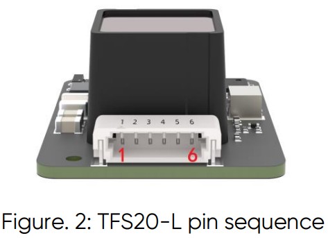
| Pin number | Function | Explanation |
| 1 | 3V3 Laser | Laser power supply |
| 2 | 3V3GND | |
| 3 | UART_TX/I2C_SDA | Transmit / Data |
| 4 | UART_RX/I2C SCL | Receive / Clock |
| 5 | GPIO | Communication chip select |
| 6 | GND | Ground |
The module supports two communication modes: UART and IIC. However, when powered on, only one interface can be selected for operation.
| UART | IIC |
 |
 |
| Connect the INT pin to ground when powering on. | When powered on, the INT pin needs to be pulled up with a 4.7K resistor or left floating. |
2.2 Serial data communication
Table. 2: Characteristics of UART
| Parameter | Default | Configurability |
| Baud rate | 115200 | Configurable |
| Data bit | 8 | Non- configurable |
| Stop bit | 1 | Non-configurable |
| Parity | None | Non-configurable |
![]() NOTICE
NOTICE
The baud rate can be set to 9600, 19200, 38400, 57600, 115200, 230400, 460800, 921600. The default baud rate of TFS20-L is 115200. When the wrong baud rate is configured, it is reset to 115200.
2.3 Serial port output format
Each data packet consists of 9 bytes of hexadecimal numbers, see the following table for details:
Table. 3: Data-packet Format
| Byte0-1 | Byte2 | Byte3 | Byte4 | Byte5 | Byte6 | Byte7 | Byte8 |
| 0x59 59 | Dist_L | Dist_H | Strength_L | Strength_H | Temp_L | Temp_H | Checksum |
| Data code explanation | |||||||
| Byte0 | 0x59, frame header, same for each frame | ||||||
| Byte1 | 0x59, frame header, same for each frame | ||||||
| Byte2 | Dist_L distance value low 8 bits | ||||||
| Byte3 | Dist_H distance value high 8 bits | ||||||
| Byte4 | Strength_L low 8 bits | ||||||
| Byte5 | Strength_H high 8 bits | ||||||
| Byte6 | Temp low 8 bits | ||||||
| Byte7 | Temp high 8 bits | ||||||
| Byte8 | Checksum is the lower 8 bits of the cumulative sum of number of first 8 bytes | ||||||
Custom Configuration
3.1 Frame definition
Customers can customize some parameters of TFS20-L, such as data frame format, frame rate, etc., which can be changed by sending specific commands. All parameters will be saved in Flash after successful configuration, and there is no need to configure them again when powering on again.
Please follow specific formats and rules when configuring parameters and avoid sending random commands.
Note: All configuration commands are sent in hexadecimal (HEX).
Table. 4: TFS20-L command format
| Byte0 | Byte1 | Byte2 | Byte3 ~ ByteN-2 | ByteN-1 |
| Head | Len | ID | Payload | Checksum |
| Command encoding explanation | ||||
| Byte0 | Header: Fixed to 0x5A | |||
| Byte1 | Len: The length of the command frame (unit: Byte) | |||
| Byte2 | ID: Identifies the function of each command | |||
| Byte3-N-2 | Data: Different meanings and lengths in different ID command frames | |||
| ByteN-1 | Checksum: the lower 8 bits of the sum of the first N-2 bytes | |||
3.2 Custom configuration
TFS20-L released several configuration parameters. These parameters, such as data format, frame rate, could be modified by certain command.
All the parameters will be stored in flash after configured successfully and customers don’t need to configure again when restart.
Please change the parameter according to certain requirements and do not frequently try irrelevant instructions. Please configure the product according to the requirements of the datasheet and don’t send unstated command.
To set the relevant parameters of TFS20-L, first connect TFS20-L to PC. For the connection method, refer to sub-section
4.2. Send relevant configuration instructions to the sensor through TF GUI software or other serial port debugging software; customers can also send relevant instructions through their own serial port tools.
After sending the parameter configuration instructions, the power needs to be turned off and settings are saved as default.
Table. 5: General Parameter Configuration and Description
| Description | Command | Response | Remarks | Default settings |
| Frame rate ① | 5A 04 01 5F④ | 5A 06 03 LL HHSU | Only supports 0/20/50/100/25 0 Hz | 100Hz |
| Instruction trigger mode | 5A 04 04 62 | Data packet | After setting the output frame rate to 0, you can trigger the sensor through this command | / |
| Output format | 5A 05 05 01 65 | 5A 05 05 01 65 | Standard 9 bytes (cm) | √ |
| 5A 05 05 06 6A | 5A 05 05 06 6A | Standard 9 bytes (mm) | / | |
| Output control ③ | On: 5A 05 07 01 67 Off: 5A 05 07 00 66 |
Same as command | / | Enabled |
| Modify baud rate ② | 5A 08 06 H1 H2H3 H4 SU | Same as command | Set the baud rate Example: 256000(DEC)=3E 800(HEX), H1=00, H2=E8, H3=03, H4=00 |
115200 |
| Enable checksum | On: 5A 05 08 01 68 Off: 5A 05 08 00 67 |
Same as command | Enable Disable | √ / |
| Signal | 5A 07 22 XX LL | Same as | Example: After | When |
| strength low threshold and low threshold output value |
HH 00 | command | Strength≤100, the Dist output value is changedto 1200. XX=100/10=10(DE C)=0A(HEX) 1200(DEC)=4B0( HEX) LL=B0,HH=04 |
Strength is less than 300, the Dist output value is 500 |
![]() CAUTION
CAUTION
- This command is mainly used to adjust the output frequency of the sensor. The default value of the output frequency is 100Hz, and custom configuration is supported, supporting frequencies are 0, 20, 50, 100, and 250Hz.
- The baud rate can be set to 9600, 19200, 38400, 57600, 115200, 230400, 460800, 921600. The default baud rate of TFS20-L is 115200. When the wrong baud rate is configured, it is reset to 115200.
- An enable data-output command must be sent each time the power is turned on.
- ‘SU’ stands for checksum and puts the lower 8 bits into the command.
- There is no need to send the save settings command. Sending a specific configuration command will take effect and be saved immediately.
For example, to change the baud rate to 460800, first change 460800 to HEX (0x00 07 08 00), then calculate the checksum to 0x77, and you can get the following instruction – 5A 08 06 00 08 07 00 77.
Do not send the command that is not in the list above.
Quick Test Guide
4.1 Tools required for test
 |
 |
 |
 |
 |
| TFS20-L | TTL-USB converter | USB cable | PC | Test Software |
4.2 Test procedures
- Download the test software
Download the latest version of test software for TFS20-L from Benewake official website:
https://en.benewake.com/DataDownload/index_pid_20_lcid_99.html
Note: Please turn off the anti-virus software before decompressing the host computer software to avoid the files in the host computer software being deleted as viruses. The host computer currently only supports running on Windows systems. - Connection of the hardware
 Connect “TFS20-L”, “TTL-USB board” and “USB cable”. Make sure there is no loose connection. Then connect “USB cable” with “PC”. As shown in the above image.
 - Connection with software
Run GUI software, select “① TFmini/TFmini-S” and select automatically recognized communication port (here it is “② COM9”), choose the right baud rate (here it is “③ 115200”), as shown in the following image.
Then click “CONNECT”. Upon successful connection, the continuous graph of the output data will be displayed in area “④ TIME LINE CHART”. Besides, the real-time data of the current measured distance (Dist), effective data points per second (Effective Points) and signal strength (Strength) will be displayed in area “⑤ REAL TIME DATA”.
Note
- If no data is available in area “④TIME LINE CHART”, please check the wire connection and sequence. When TFS20-L is successfully powered on, there will be a faint red light inside transmitting lens viewing from the front using mobile phone camera or any other IR light detecting device.
- The value of distance output Dist may vary with the output unit, which is cm by default. If the unit of distance is changed to the unit-mm with specific command, and the PC software will be unable to identify it, and so the unit of “④TIME LINE CHART” will still be cm. For example, the actual TFS20-L measurement is 1m, the distance value of TFS20-L is 1000 in mm, the value read by the PC software also is 1000, but the unit will not change and still display cm.
Q&A
① After the LiDAR is connected to the host computer, there is no data output.
Cause-1: TTL-USB board connection is bad. Solution: Check whether the connection between TTL-USB board, TFS20-L and PC is correct and reliable. Cause-2: The serial port driver is not installed correctly. Solution: Re-plug the USB cable and try to re-install the driver, or search the Internet for the driver to download and install. If you still cannot use the host computer normally, please contact our technical support.
② TFS20-L will heat up after working for a period of time.
Explanation: This is the normal working state of the product. After the chip and circuit board continue to work, slight heating is normal.
③ TFS20-L has no data output.
Cause-1: The V1.40C version does not output data by default when powered on, and you need to send an output enable command (as mentioned in Table 5). Solution: Send the output enable command 5A 05 07 01 67 after powering on. Cause-2: The product will be strictly inspected before leaving our factory, ensuring that all the shipped products can work normally. However, some abnormal working matters maybe still occur because of incidents during the transportation or use. Solution: Check whether the power supply is normal and whether the voltage is within the rated voltage range. If the power supply is normal, there should be a faint red light in the TFS20-L transmitting lens. Check whether the wiring sequence of TFS20-L is correct and whether the connection is reliable. Check whether the data parsing is correct. Please parse it according to the data format described in the manual. If the problem is still not solved, please contact technical support.
④ Does TFS20-L support ultra-low power mode?
Answer: No, it does not support. The current standby power consumption is about 145 mW. The average power consumption is about 350 mW. If powered by a 10000mAh battery, it can last about 6 days.
![]() © 2024 Benewake (Beijing) Co., Ltd. ·
© 2024 Benewake (Beijing) Co., Ltd. ·
All rights reserved · REV: 01/09/2024
Documents / Resources
 |
Benewake TFS20-L Miniaturized Single Point LiDAR Module [pdf] User Manual TFS20-L Miniaturized Single Point LiDAR Module, TFS20-L, Miniaturized Single Point LiDAR Module, Single Point LiDAR Module, Point LiDAR Module, LiDAR Module, Module |