![]() Installation/ User Manual
Installation/ User Manual
APsmart Rapid Shutdown Device & Transmitter
Rev2.92023/10/07
 RSD-D
RSD-D
TRANSMITTER-PLC
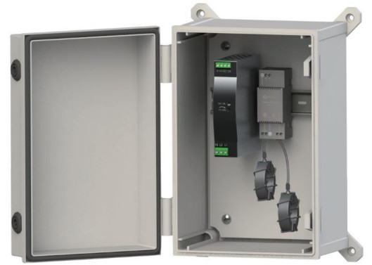
TRANSMITTER-PLC OUTDOOR KIT
IMPORTANT SAFETY INSTRUCTIONS
This manual contains important instructions to be followed during installation and maintenance of the APsmart RSD-D and Transmitter. To reduce the risk of electrical shock and ensure the safe installation and operation of the APsmart RSD-D and Transmitter, the following symbols appear throughout this document to indicate dangerous conditions and important safety instructions.
Safety Instructions
- Do NOT disconnect the PV module from the RSD-D without first disconnecting the AC power.
- Only qualified professionals should install and/or replace the APsmart RSD-D.
- Perform all electrical installations in accordance with local codes.
- Before installing or using the RSD-D, please read all instructions and cautionary markings in the technical documents.
- Be aware that the body of the operating RSD-D is a heat sink and can reach high temperature. To reduce risk of burns, do not touch the body of the RSD-D.
- Do NOT attempt to repair the RSD-D. If it fails, contact APsmart Customer Support to obtain an RMA number and start the replacement process. Damaging or opening the RSD-D will void the warranty.
The power supply of the Transmitter-PLC and inverter MUST be on the same AC branch circuit as the inverter to meet rapid shutdown requirements.
This device complies with part 15 of the FCC Rules, Operation is subject to the following two conditions:
- This device may not cause harmful interference, and
- this device must accept any interference receiver, including interference that may cause undesired operation.
Qualified Personnel:
Person adequately advised or supervised by an electrically skilled person to enable him or her to perceive risks and to avoid hazards which electricity can create. For the purpose of the safety information of this manual, a “qualified person” is someone who is familiar with requirements for safety, electrical systems and EMC and is authorized to energize, ground, and tag equipment, systems, and circuits in accordance with established safety procedures. The inverter and balance of system may only be commissioned and operated by qualified personnel.
RSD PRODUCTS
RSD-D
- Meets NEC 2017, 2020&2023 (690.12) requirements
- Executes rapid shutdown of system when Transmitter-PLC signal is absent
- Meets SunSpec requirements
- Dual-input channel
The RSD-D meets SunSpec requirements, maintaining normal function by continually receiving a heartbeat signal from the APsmart Transmitter. The RSD-D executes rapid system shutdown when the Transmitter signal is absent. Users can manually execute rapid shutdown using the Transmitter breaker switch.*(1)(2)
*(1) RSD-D does not have automatic shutdown function for arc detection. When the system is abnormal, the transmitter signal is cut off by pulling the gate, which triggers shutdown.
*(2) RSD-D is designed to reduce the risk of fire suppression but does not solve the risk of a arc fire.
TRANSMITTER PRODUCTS
Transmitter-PLC
- Meets NEC 2017, 2020&2023 (690.12) requirements
- Switching off Transmitter-PLC results in rapid shutdown of the output of PV modules
- Meets SunSpec requirements
- Equipped with single/dual core
- Optional 85-264VAC power supply
- Optional 180-550VAC power supply
Transmitter-PLC-Outdoor Kit
- Meets NEC 2017, 2020&2023 (690.12) requirements
- Switching off Transmitter-PLC results in rapid shutdown of the output of PV modules
- Meets SunSpec requirements
- Equipped with single/dual core
- Optional 85-264VAC power supply
- Optional 180-550VAC power supply
SYSTEM WIRING DIAGRAM
The APsmart Rapid Shutdown System Transmitter-PLC is part of a rapid shutdown solution when paired with the APsmart RSD-D, a PV module rapid shutdown unit. While powered on, the Tansmitter-PLC sends a signal to the RSD-D units to keep the PV modules connected and supplying energy.
RSD-D units automatically enter rapid shutdown mode when the Transmitter-PLC is switched off and resume energy production when power is restored to the Transmitter-PLC. This solution complies with NEC 690.12 specifications for 2017, 2020 & 2023 and supports the SunSpec signaling for rapid shutdown.
The Transmitter-PLC includes one or two cores and an optional power supply: 85-264VAC for residential, 180-550VAC for commercial.
The Transmitter-PLC Outdoor Kit includes a Transmitter-PLC with one or two cores, outdoor enclosure, 85-264VAC or 180V-550VAC power supply. It could be used in a residential or commercial project.
- RSD-D
- Transmitter-PLC
- Inverter

- RSD-D
- Transmitter-PLC-Outdoor Kit
- Inverter

- RSD-D
- Transmitter-PLC-Outdoor Kit
- Inverter
- Emergency stop button box(optional): Press the emergency stop button, the transmitter AC power supply is disconnected, the RSD closes the output, and the system rapid shutdown.

- RSD-D
- Inverter*
*Inverter in diagram includes an integrated SunSpec-certified Rapid Shutdown Transmitter.
RSD-D INSTALLATION
INSTALLATION NOTES
Installation MUST comply with local regulations and technical rules:
- Perform all electrical installations in accordance with local codes.
- Be aware that only qualified professionals should install and/or replace the RSD-D.
- Before installing or using an RSD-D, please read all instructions and warnings in the technical documents and on the inverter system itself as well as on the PV array.
- Be aware that installation of this equipment includes the risk of electric shock.
- Do not touch any live parts in the system, including the PV array, when the system has been connected to the electrical grid.
- Ensure the PV module and inverter have been disconnected before installing an RSD-D.
- Do not attaching negative power wires in the homerun on any RSD devices or connectors.
- Be sure to verify the voltage and current specifications of your PV module match with those of the RSD-D.
- The maximum open circuit voltage of the PV module must not exceed the specified maximum input voltage of the APsmart RSD-D.
Additional installation components from APsmart
- DC extension cable (sold separately)
Required parts and tools to complete the installation
In addition to your PV array and its associated hardware, you will need a torque wrench and a Phillips screwdriver.
Step 1: Install the RSD-D. Buckle RSD-D onto the PV module frame.
 NOTE: Do not place the RSD-D (including DC connectors) where exposed to the sun, rain or snow, even gap between modules. Allow a minimum of 3/4’’(1.5cm.) between the roof and the bottom of the RSD-D to allow proper air flow.
Step 2. Connect the INPUT1 connectors of the RSD-D to the first PV module junction box and connect the INPUT2 connectors to second PV module, the device DC output voltage is within the range of 1.2 ~ 2v.
NOTE: Do not short-circuit the RSD-D output connectors, otherwise it will be damaged.
RSD-D cable length NOTE: The output cable length of triad junction box PV module should be no less than 1.2m.
 NOTE: The output cable length of integrated junction box PV module should be no less than 0.9m.
 NOTE: When installing RSD-D cable, the bending radius of the cable near the casing must be greater than 50 mm.
 Step 3: Connect the output ports of two adjacent RSD-Ds in series and then connect to the inverter with a self-made DC extension cable.
NOTE: Do not connect homerun to inverter before finishing all strings connections and tests.
WARNING: When connecting the RSD-D to only one PV module, use INPUT1 port ONLY, then short both terminals of INPUT2 directly, otherwise the RSD-D may be damaged. The DC output voltage remain same.
NOTE: Please use the same type of DC connector as the RSD in the system. The RSD damage caused by using different type of DC connector will not be covered by the warranty.
TRANSMITTER-PLC INSTALLATION
 Note: If there is only one core needed, connect using Core 1 terminal.
Transmitter-PLC power supply must be on same AC branch circuit as inverter to meet rapid shutdown requirements.
During operation, the Power LED should be lit and the Signal LED should be blinking. If the Transmitter-PLC fails to work, the Signal LED will not be blinking. If the Power LED is also not lit, check the power supply first.
NOTE: Install the RSD-D before powering on the Transmitter-PLC.
- Mount Transmitter-PLC and power supply on DIN rail
- Connect DC leads from power supply to Transmitter-PLC
- Connect single/dual core(Core 1 and Core 2) to Transmitter-PLC
Place rapid shutdown system label no more than 1m (3ft) from Transmitter-PLC or AC disconnect if not at same location. NOTE: Install the RSD-D before powering the Transmitter-PLC.
NOTE: The waterproof jacket and related accessories are not configured before delivery and customers need to buy by themselves.
- Pass either positive or negative cables through cores (either both positive cables or both negative cables. Do not use one positive and one negative cable.)
- Connect wires to AC side of power supply
Max number of Strings Per Core :
| DC cable Diameter(without connector) | Φ5.9mm | Φ6.35mm | Φ7mm | Φ8.6mm |
| 29mm Core | ≤15 | ≤15 | ≤14 | ≤10 |
| 11mm Core | ≤6 | ≤5 | ≤4 | ≤2 |
Max string length : 30 modules
Max current per core : 160A(29mm)/75A(11mm)
Max cable length from inverter(+) to inverter(-) : 1500ft (450m)
Drilling Guide for .75″ Conduit Drilling Guide for 1″ Conduit
 NOTE: The Outdoor Kit was not punched before delivery and customer need to make it themselves according to the actual situation. The figure is only for reference.
TECHNICAL DATA—RSD-D
| Model | RSD-D-15 I | RSD-D-20 |
| Input Data (DC) | ||
| Range of Input Operating Voltage | 8.65V Per Channel | |
| Maximum Cont. Input Current (Imax) | 15A Per Channel | 20A Per Channel |
| Maximum Short Circuit Current (lsc) | 25A | |
| Output Data (DC) | ||
| Range of Output Operating Voltage | 16-130V | |
| Maximum Output Current | 15A | 20A |
| Maximum System Voltage | 1000V/1500V | |
| Maximum Series Fuse Rating | 30A | |
| Mechanical Data | ||
| Operating Ambient Temperature Range | -40 °F to +167°F (-40 °C to + 75 °C) | |
| Dimensions (without cable & connectors) | 5.5″ x 2″ x 0.8°(140 mm x 50.6 mm x 20 mm) | |
| Cable Length | Input 500mm/Output 2400mm | |
| Cable Cross Section Size | TUV:4mm7/UL:12AWG | |
| Connector | Input: Stäubli MC4 PV-KBT4&KST4 or Customize | |
| Output: APsystems specified or Customized | ||
| Enclosure Rating | NEMA Type 6P/IP68 | |
| Protection Temperature | 100°C | |
| Features & Compliance | ||
| Communication | PLC | |
| Safety Compliance | NEC 2017, 2020&2023 (690.12); UL1741; CSA C22.2 No. 330-17; IEC/EN62109-1 |
|
| EMC Compliance | FCC Part15; ICES-003 | |
TECHNICAL DATA—TRANSMITTER-PLC
| Model | Transmitter-PLC |
| Main electrical data | |
| Input Voltage | 12VDC |
| Input Current | 0.8A |
| Communication | PLC |
| Power Supply | |
| Residential(optional) | 85-264VAC Input, 12VDC Output, 90 mm x 17.5 mm x 58.4 mm |
| Commercial(optional) | 180-550VAC Input, 12VDC Output, 125.2 mm x 32 mm x 102 mm |
Core data
| Core data | 29mm Core | 11mm Core |
| Max. Current | 320A (160A*2) | 150A (75A*2) |
| Max. System Voltage | 1500VDC | |
| Internal Opening for Wires/Outside Dimensions | ~29mm/65mm | ~11mm/42mm |
| Max. Supported PV Modules per String | 30 modules | |
Number Of Strings Per Core
| DC cable Diameter(without connector) | Φ5.9mm | Φ6.35mm | Φ7mm | Φ8.6mm |
| 29mm Core | ≤15 | ≤15 | ≤14 | ≤10 |
| 11mm Core | ≤6 | ≤5 | ≤4 | ≤2 |
| Environmental | |
| Temperature | -40°C~+100°C |
| Structure data | |
| Dimensions (W x H x D) | 90 mm x 35 mm x 40 mm |
| Enclosure Environmental Rating | IP30 |
| Features & Compliance | |
| Safety Compliance | NEC 2017, 2020&2023 (690.12); UL1741; CSA C22.2 No. 330-17 |
| EMC Compliance | FCC Part15; ICES-003 |
TECHNICAL DATA—TRANSMITTER-PLC-OUTDOOR KIT
| Model | Transmitter-PLC-Outdoor Kit |
| Main electrical data | |
| Input Voltage | 12VDC |
| Input Current | 0.8A |
| Communication | PLC |
| Power Supply | |
| Residential(optional) | 85-264VAC Input, 12VDC Output, 90 mm x 17.5 mm x 58.4 mm |
| Commercial(optional) | 180-550VAC Input, 12VDC Output, 125.2 mm x 32 mm x 102 mm |
| Core data | |
| M29mm Core | 320A (160A*2) |
| ax.Current | 1500VDC |
| 150A Per core | ~29mm/65mm |
| Max. System Voltage | 30 modules |
Number Of Strings Per Core
| DC Cable Diameter(without connector) | Φ5.9mm | Φ6.35mm | Φ7mm | Φ8.6mm |
| 29mm Core | ≤15 | ≤15 | ≤14 | ≤10 |
| Environmental | |
| Temperature | -40°C~+60°C |
| Structure data | |
| Dimensions (W x H x D) | 198.5 mm x 298 mm x 179 mm |
| Enclosure Environmental Rating | IP30 |
| Features & Compliance | |
| Safety Compliance | NEC 2017, 2020&2023 (690.12); UL1741; CSA C22.2 No. 330-17 |
| EMC Compliance | FCC Part15; ICES-003 |
![]() 8627 N Mopac Expy, Suite 150
8627 N Mopac Expy, Suite 150
Austin, TX 78759 | +1-737-218-8486
+1-866-374-8538
support@APsmartGlobal.com
APsmartGlobal.com
Documents / Resources
 |
APsmart RSD-D Rapid Shutdown Device and Transmitter [pdf] Installation Guide RSD-D, RSD-D Rapid Shutdown Device and Transmitter, Rapid Shutdown Device and Transmitter, Shutdown Device and Transmitter, Device and Transmitter, Transmitter |