Alarm com ADC SEM300 Communicator

Product Information
Specifications:
- Product Name: SEM300
- Default Keypad Address: Keypad 8 Device Address 23
Product Usage Instructions
Addressing the Keypad:
The default keypad address for the SEM is Keypad 8 Device Address 23. To enable or change the keypad address:
- Access VISTA programming mode.
- Enter the corresponding command based on the desired addresssetting (e.g., *196 for Keypad Address 23).
- Adjust the DIP switches on the SEM accordingly to match the desired address.
- Exit programming mode by entering *99.
GATEWAY LED Reference:
The enclosure gateway LEDs provide information on communication errors, panel communication, network communication, and signal strength. For advanced troubleshooting, check the Alarm.com module LEDs by opening the cover.
TROUBLE LED:
The TROUBLE LED flashes in specific patterns to indicate error conditions. Here are some common flash patterns and their descriptions:
-
- Flash Pattern 1: Communication issue between Alarm.com module and panel. Perform a power cycle and re-insert the module if needed.
- Flash Pattern 2 then 4: Provisioning process error. Contact Alarm.com CORE Technical Support if issue persists.
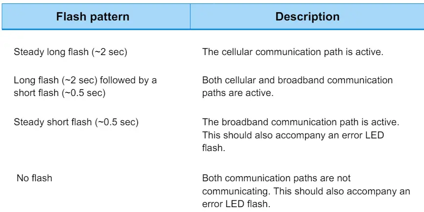
PATH LED:
The PATH LED flashes to show the active communication path to Alarm.com (cellular, broadband, or both). Different flash patterns indicate different paths.
Frequently Asked Questions
- Q: What should I do if I encounter a TROUBLE LED flash pattern that is not listed in the manual?
- A: For any TROUBLE LED flash pattern not listed, please contact Alarm.com CORE Technical Support for assistance.
- Q: How can I check the signal strength of the cellular network for the SEM?
- A: To check the signal strength, monitor the L4 signal level on the SEM. If it’s lower than 2 bars, consider changing the panel’s location or using a remote antenna option.
ADDRESSING THE KEYPAD
The default keypad address the SEM uses is Keypad 8 Device Address 23. If this keypad address is disabled, the SEM and panel will not communicate properly. However, at first power-up, the SEM will attempt to enable this address automatically. If unsuccessful, the address must be enabled manually via programming *196.

If another keypad is occupying this address already, a different address must be selected for the SEM. To select a different keypad address, manually adjust the dual in-line package DIP switches on the SEM to match the desired keypad address listed below. Then, exit programming via *99.
GATEWAY LED REFERENCE
The enclosure gateway LEDs can be used to indicate communication errors, panel communication, network communication, and signal strength.
Note: For advanced troubleshooting, open the cover to look at the Alarm.com module LEDs.
 TROUBLE LED
The TROUBLE LED flashes 1 to 8 times in a four-second interval to indicate specific error conditions.


8 Email cs@alarmsystemstore.com or call Alarm System Store for assistance: 888-811-0727
 PATH LED
The PATH LED flashes to indicate the active communication path (cellular, broadband, or both) to Alarm.com.
 SIGNAL LED
The SIGNAL LED flashes to indicate the cellular signal strength (0 to 6 bars).
 PANEL LED
The PANEL LED flashes with every communication to the panel.
 POWER LED
The POWER LED illuminates solid when power is supplied.
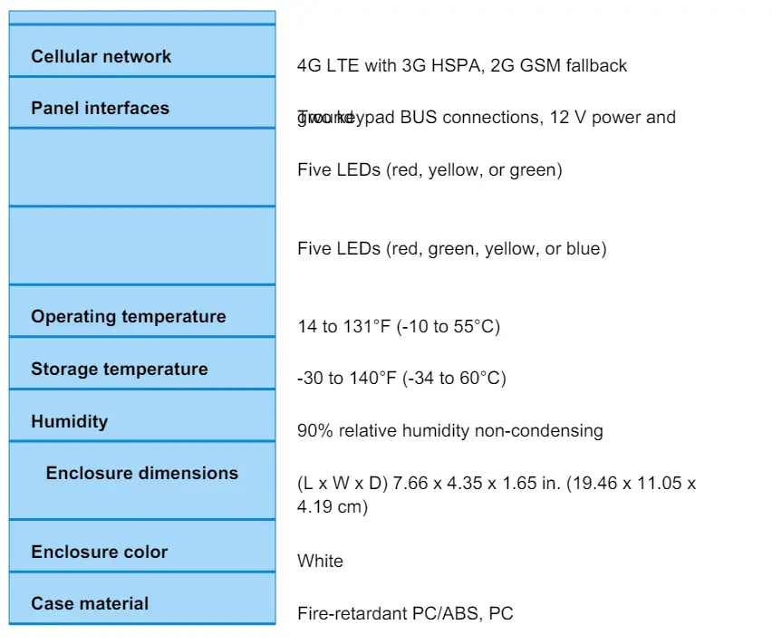
SPECIFICATIONS

Documents / Resources
 |
Alarm com ADC SEM300 Communicator [pdf] Installation Guide ADC SEM300 Communicator, ADC SEM300, Communicator |


