Akuvox E18 Door Intercom and Access Control Unit
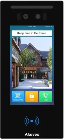
Specifications
- White Light LED
- Infrared LED Camera
- Face-liveness Detection Camera
- LCD Card Reader
- Photosensitive Sensor
- Speaker
Product Usage Instructions
E18 Wiring Interface
To protect the device from over-voltage, wire a diode into the circuit connecting the anode to the negative cable of the lock and the cathode to the positive cable of the lock.
Unpacking
Before using the device, check the device model and ensure that the shipped box includes the following items:

Product Overview

Before You Start
Tools needed
(not included in shipped box)
- Cat Ethernet Cable
- Crosshead Screwdriver
- Electric Drill
Voltage and Current Specifications
- It is suggested that use PoE or 12VDC 2A power adapter to power on device.
AWG Sizes and Properties Table
Please follow the properly wire data to install device:
| Power Supply | 12VDC 2A | |
| AWG | 20 | 22 |
| Resistance (ohm/km) | 33.9 | 48.5 |
| Cross-sectional Area (mm²) | 0.5189 | 0.3247 |
| Wire Length (m) | ≤20 | ≤10 |
Requirements
- Place the device away from sunlight and light sources to prevent potential damage.
- Do not place the device in the high-temperature, and humid environments or in surroundings impacted by magnetic field.
- Install the device on the flat surface securely to avoid personal injuries and property loss caused by device’s falling.
- Do not use or place the device near heating objects.
- If installing the device indoors, please keep device at least 2 meters away from light, and at least 3 meters away from window and door.

Warning!
- To ensure safety, avoid touching power core, power adapter, and device with wet hands, bending or pulling the power core, damaging any components, and use only qualified power adapter and power cord.
- Be careful that standing up on the area under the device in case of personal injuries cause by hitting the device.
Cautious
- Do not knock device with hard objects.
- Do not press down hard on the device screen.
- Do not expose device to chemical products, such as alcohol, acid liquid, disinfectants, and so on.
- To prevent the device installation from becoming loose, ensure accurate diameters and depths of screw holes. If the screw holes are too large, use glue to secure the screws.
- Use wet cloth clean device surface softly, and then wipe the surface with dry cloth for cleaning the device.
- If there is abnormal situation of the device, including uncommon sound and smell, please power off the device and contact Akuvox Technical Team immediately.
Wiring Interface

To protect the device from potential damage caused by over-voltage, it is recommended to wire a diode into the circuit. Connect the anode of the diode to the negative cable of the lock, and connect the cathode of the diode to the positive cable of the lock.

Installation
Step 1 : Flush-mounting Box Installation

Dig out a square hole with dimension 320*145*56mm (height*width*depth) according to the position of cable.
- Place the flush-mounting box in the hole.
- Mark six positioning holes of the flush-mounting bracket on the wall.
Note: The positioning holes should be marked in the center of the holes.

- Remove the flush-mounting box.
- Use an electric drill with a 6mm diameter bit to make four holes with 20mm in depth in the marked holes.

- Insert six plastic wall anchors into the drilled holes.
- Fix the flush-mounting box with six ST4X20 crosshead screws, which make flush-mounting box attach the wall.

- Flush-mounting box installation is finished.
Step 2: Main Unit Installation

- As shown in the picture, combine bracket, device, and plate together. Secure them by fixing six M3x8 crosshead screws.
- Lead the wires from the flush-mounting box through the plate, sealing ring, and wiring cover.
- Connect wires to the corresponding interface as needed (for details, refer to “Wiring Interface”).
- Put sealing ring into the groove, close wiring cover. Then select a suitable rubber plug to push all the cables into the wiring cover.
- Fix wiring cover on the back cover with four M3X5 crosshead screws. Then use two ST1.7X4 crosshead screws to tighten sealing pressing plate.
Step 3 : Device Installation

- Use two M4 x 16 crosshead screws to secure device and its component onto the flush-mounting box.
- Installation is completed.
Application Network Topology

Device Test
Please verify the device status after installation:
- Network: Long press screen for 5 seconds and enter default password admin, then tap Confirm to access System Info page. Check the device’s IP address and network status. Network is working properly if the IP address is obtained.
- Intercom: Tap Dial key, enter the IP or SIP number and press Dial key to make a call. Or, tap APT number to call. The call configuration is correct if the call is successful.
- Access Control: Use pre-configured PIN code, RF card, and face to unlock door.
Warranty
- Akuvox warranty does not cover intentional mechanical damage or destruction caused by improper installation.
- Do not attempt to modify, alternate, maintain, or repair device by yourself. Akuvox warranty does not apply to damages caused by anyone who is not representative of Akuvox or an Akuvox authorized service provider. Please contact Akuvox Technical Team if the device need to be repaired.
Get Help
For help or more assistance, contact us at: https://ticket.akuvox.com/
support@akuvox.com
Scan the QR code to get more videos, guides, and additional product formation.

Notice Information
Information contained in this document is believed to be accurate and reliable at the time of printing. This document is subject to change without notice, any update to this document can be viewed on Akuvox’ s website: http://www.akuvox-.com © Copyright 2024 Akuvox Ltd. All rights reserved.

Frequently Asked Questions
- Q: What should I do if there is an uncommon sound or smell from the device?
A: Power off the device immediately and contact Akuvox Technical Team for assistance.
Documents / Resources
 |
Akuvox E18 Door Intercom and Access Control Unit [pdf] User Guide E18, E18 Door Intercom and Access Control Unit, Door Intercom and Access Control Unit, Access Control Unit |


