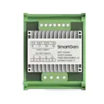
SmartGen SGCAN300 Canbus Relay Module

SmartGen — make your generator smart SmartGen Technology Co., Ltd. No.28 Jinsuo Road, Zhengzhou, Henan Province, China
- Tel: +86-371-67988888/67981888/67992951 +86-371-67981000(overseas)
- Fax: +86-371-67992952
- Email: sales@smartgen.cn
- Web: www.smartgen.com.cn
All rights reserved. No part of this publication may be reproduced in any material form (including photocopying or storing in any medium by electronic means or other) without the written permission of the copyright holder.
Applications for the copyright holder’s written permission to reproduce any part of this publication should be addressed to SmartGen Technology at the address above. Any reference to trademarked product names used within this publication is owned by their respective companies. SmartGen Technology reserves the right to change the contents of this document without prior notice.
Table 1 – Software Version
| Date | Version | Note |
| 2020-08-28 | 1.0 | Original release. |
Notation Clarification
| Sign | Instruction |
| NOTE | Highlights an essential element of a procedure to ensure correctness. |
| CAUTION! | Indicates a procedure or practice, which, if not strictly observed, could result in
damage or destruction of equipment. |
|
WARNING! |
Indicates a procedure or practice, which could result in injury to personnel or loss of life if not followed correctly. |
OVERVIEW
SGCAN300 CANBUS RELAY MODULE can realize the mutual conversion between MSC1 and optical fiber, MSC1 and MSC2, RS485 and optical fiber. Using the module can increase the communication distance of MSC or RS485.
PERFORMANCE AND CHARACTERISTICS
- With conversion function of MSC1 and optical fiber, using a pair of modules can realize long distance MSC communication;
- With conversion function of RS485 and optical fiber, using a pair of modules can realize long distance RS485 communication;
- With data conversion function of MSC1 and MSC2, using a single module can increase the MSC communication distance;
- With one digital input, which can control signal conversion enabling;
- The effective type of input port can be set by the dial switch of the module;
- The baud rates of MSC1 and MSC2 can be set by the dial switch of the module;
- The baud rate of RS485 can be set by the dial switch of the module.
SPECIFICATION
| Items | Contents |
| Operating Voltage | DC 8V~35V, Continuous Power Supply, DC Reverse Connection
Protection |
| Power Consumption | <2W |
| RS485 Port | Isolation, Half Duplex, Baud Rate: 9600bps and 19200bps are optional |
| CAN Port | Isolation, Baud Rate: 50kbps, 125kbps, 250kbps and 500kbps are optional |
| Optical Fiber Port | Max. Transmission Distance: 10km, Type: SC |
|
Vibration |
5 – 8 Hz: ±7.5 mm
8 – 500 Hz: 2 g IEC 60068-2-6 |
|
Schock |
50 g, 11 ms, half sine, finish the shock test from three directions. There are total 18 shocks per test.
IEC 60068-2-27 |
| Collision | 25g, 16ms, half sine
IEC 60255-21-2 |
| Case Dimensions | 71.6mm x 92mm x 60.7mm |
| Installation | 35mm Guide Rail Mounting |
| Working Conditions | Temperature: (-25~+70)°C Humidity: (20~93)%RH |
| Storage Condition | Temperature: (-30~+80)°C |
| Weight | 0.2kg |
OPERATION
PANEL INDICATION
NOTE: Partial indicator description.
Indicators Description
| Indicator | Note |
| POWER | Normally light on |
| DIN | Normally light on when effective |
| TX | Fast flash (5 times per second) when sending the data |
| RX | Fast flash (5 times per second) when receiving the data |
Table 5 –Dial Switch Functions
| Dial Sequence | Function |
| 1 | Effective Type of Input Port 0: Close is effective 1: Open is effective |
| 2 | MSC1 Baud Rate 00:250kbps
01(The third is 1):50kbps 10(The second is 1):125kbps 11:500kbps |
| 3 | |
| 4 | MSC 2 Baud Rate 00:250kbps
01(The fifth is 1):50kbps 10(The fourth is 1):125kbps 11:500kbps |
| 5 | |
| 6 | RS485 Baud Rate 0:9600bps 1:19200bps |
| 7 | Optical Fiber Mode 0: Optical fiber is connected with CAN1.
(Input port should be effective) 1: Optical fiber is connected with RS485. (Input port should be effective) |
| 8 | Test Mode 1: Lamp test function. Each dial switch corresponds to an LED
indicator light, light on when is 1. |
NOTE: “ON” of dial switch is 1 and “Non-ON” is 0. There need power on again when baud rate changed.
MUTUAL CONVERSION OF MSC1 AND OPTICAL FIBER
When the digital input is effective, the dial switch 7 is placed to Non-ON, at which time the MS1 is connected with the optical fiber. The baud rate can be selected by dial switch 2 and 3. The other SGCAN300 module will go to the same setup. Connecting the optical fiber communication lines of two SGCAN300 modules, then the MSC1 interface of the two modules can be converted through the optical fiber.
MUTUAL CONVERSION OF RS485 AND OPTICAL FIBER
Place the dial switch 7 to ON, then the RS485 is connected with the optical fiber. The baud rate can be selected by dial switch 6. The other SGCAN300 module will go to the same setup. Connecting the optical fiber communication lines of two SGCAN300 modules, then the RS485 interface of the two muddles can be converted through the fiber.
MUTUAL CONVERSION OF MSC1 AND MSC2
When the digital input is effective, then the MSC1 is connected with the MSC2. The baud rate can be selected by dial switch 2,3,4,5, then the interfaces of MSC1 and MSC2 are converted
WIRING CONNECTION
The panel of SGCAN300 is as follows: 
Table 6 – Terminal Connection Description
| No. | Function | Cable
Size |
Note |
| 1 | DC Power Input B- | 1.0mm2 | Connect with negative pole of DC power. |
| 2 | DC Power Input B+ | 1.0mm2 | Connect with positive pole of DC power. |
| 3 | Programmable Digital
Input |
0.5mm2 | Connecting with B- is effective, it is used for bus switch
status judgement. |
| 4 | RS485-TR | 0.5mm2 | If terminal resistance matching is required to short
connect with Terminal 5, otherwise it is suspended. |
| 5 | RS485-A(+) | 0.5mm2 | RS485 communication interface. |
| 6 | RS485-B(-) | 0.5mm2 | |
| 7 | MSC1-TR | 0.5mm2 | If terminal resistance matching is required to short
connect with Terminal 8, otherwise it is suspended. |
| 8 | MSC1-CANH | 0.5mm2 | CANBUS communication interface. |
| 9 | MSC1-CANL | 0.5mm2 | |
| 10 | MSC2-TR | 0.5mm2 | If terminal resistance matching is required to short
connect with Terminal 11, otherwise it is suspended. |
| 11 | MSC2-CANH | 0.5mm2 | CANBUS communication interface. |
| 12 | MSC2-CANL | 0.5mm2 | |
| 13 | FIBER-TX | / | Optical fiber communication interface, SC connector
with lock. |
| 14 | FIBER-RX | / |
TYPICAL APPLICATION

CASE DIMENSIONS AND INSTALLATION

TOUBLESHOOTING
Table 7 –Troubleshooting
| Symptoms | Possible Solutions |
|
Communication failure of MSC1 and MSC1 of the other module |
1.Check communication line and communication terminal resistance; 2.Check digital input status and effective type;
3. Check whether the communication baud rate is consistent with the controller; 4. Check whether the dial switch 7 is Non-ON; 5. Observe the communication indicator light to judge the communication error. |
|
Communication failure of RS485 and RS485 of other module |
1.Check communication line and communication terminal resistance; 2.Check whether the communication baud rate is consistent with the controller;
3. Check whether the dial switch 7 is ON; 4. Observe the communication indicator light to judge the communication error. |
|
Communication failure of MSC1 and MSC2 |
1. Check communication line and communication terminal resistance;
2. Check digital input status and effective type; 3. Check whether the communication baud rate is consistent with the controller; 4.Observe the communication indicator light to judge the communication error. |
| There is no response for power
on and all lights are off |
Check dial switch 8 and it should be Non-ON. |
- SGCAN300 CANBUS Relay Module
- Version 1.0
Documents / Resources
 |
SmartGen SGCAN300 Canbus Relay Module [pdf] User Manual SGCAN300, Canbus Relay Module, SGCAN300 Canbus Relay Module, Relay Module |