![]() SM05 NTSC PAL Video Encoder Module
SM05 NTSC PAL Video Encoder Module
User Manual
Introduction
SM05 is a broadcast-quality NTSC/PAL video encoder module.
The SM05 accepts SDI video (SMPTE-259M) which is then encoded to broadcast quality NTSC or PAL video output. For driving long lengths of cable pre-emphasis may be applied to the output to boost high frequencies and compensate for cable attenuation.
In the absence of the SDI input, the output will switch to a color bar pattern.
The SM05 requires 5VDC power which is provided via the supplied AC-DC converter.
Connecting up the module
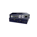
A plan view of the SM05 module is shown in Figure 1.

Figure 1 SM05 Connections.
SM05 requires a 5VDC supply which is provided via the supplied AC-DC adaptor. The adaptor accepts AC between 100 and 240VAC – the full specification is provided in Appendix A.
Connect the 5VDC jack from the adaptor to the +5VDC socket on the SM05. The yellow ‘FPGA Configured’ LED (in the RJ-45 differential out connector) should light showing the FPGA has been configured successfully and the board is ready for use.
Connect the CVBS output to a monitor. By default, the output will be 75% NTSC color bars.
Connect up a valid SDI input (525i or 625i, SMPTE-259M). If the SDI input can lock to the signal the SDI Lock LED will light and the CVBS output will switch to the SDI input. The SM05 auto detects the input standard. If the SDI input is lost, the SM05 will revert to a color bar output at the last SDI standard.
SM05 provides simultaneous single-ended coaxial and differential twisted-pair (UTP) outputs. The UTP outputs are connected via an RJ45-style connector. Figure 2 shows the pin assignments for the connector: (pin 1 for the ‘VIDEO+’ (non-inverted) signal, and pin 2 ‘VIDEO-‘ (inverted) signal).
When driving long lengths of cable, especially UTP and low-cost coaxial cable (e.g. RG-59) there is a high-frequency loss. Usually, this is compensated for by adding high-frequency peaking at the receiver. However, this impacts negatively on the signal-to-noise ratio of the video. Therefore, the SM05 allows you to add high-frequency pre-emphasis to the CVBS output. You can adjust the pre-emphasis in eight steps using the rotary ‘pre-emphasis switch. Up to 6dB of high-frequency gain may be applied, which compensates for up to 300m of UTP or coaxial cable. The frequency response of the pre-emphasis filter is shown in Figure 3.

Figure 2 SM05 UTP connections.

Reprogramming the FPGA
The FPGA may be reprogrammed to install new features or improvements. As the SM05 uses an Altera FPGA it is necessary to download the Quartus programmer software. This may be downloaded from the SingMai website using the following links: https://www.singmai.com/Quartus/QuartusProgrammerSetup-17.1.0.590-windows.exe
(64-bit version) https://www.singmai.com/Quartus/QuartusProgrammerSetup-17.1.0.590-windows32.exe (32-bit version)
The files are 365MB in size, so downloading may take a little time.
Also, it is necessary to use the USB-Blaster module: we use the Terasic version: https://www.terasic.com.tw/cgi-bin/page/archive.pl?Language=English&No=46
Once the programmer file is downloaded, double-click it and you should see this screen.

Figure 4 Quartus Programmer installation – Screen 1.
Click Next and you should see this screen. 
Figure 5 Quartus Programmer installation – Screen 2.
Click the ‘I accept the agreement box and then Next. 
Figure 6 Quartus Programmer installation – Screen 3.
Make a note of the installation directory and then click Next.

Figure 7 Quartus Programmer installation – Screen 4.
Click Next and the installation should begin.

Figure 8 Quartus Programmer installation – Screen 5.

Figure 9 Quartus Programmer installation – Screen 6.
Unclick the Signal Tap and System Console boxes and then click Finish. You should then see the Device Driver installation Wizard.

Figure 10 Quartus Programmer – Device Installation.

Figure 11 Quartus Programmer – Device Installation.
The device driver does not always install correctly and, if not, has to be manually installed.
Download the drivers from the SingMai website: https://www.singmai.com/Quartus/usb-blaster.zip
Place this file in the same directory as the programmer installation directory as shown in Figure 12 and unzip the file to there.

Plug in the USB Blaster to a USB port and you should be prompted for a driver – choose to browse to point to the usb-driver directory (only point to the top level, not any sub-directories). If the driver installation is not automatic, it is necessary to go to the Device Manager and manually install the driver from there.
Open the Quartus programmer if it is not already open. You should see a screen similar to the one below.
Figure 13 Quartus Programmer screen.
Click on Hardware setup and choose the USB Blaster.

The USB-Blaster 10-way header plugs into J3, and the 10W header on the SM05. The header is polarized to ensure the cable cannot be inserted the wrong way (see Figure 15).

Figure 15 Re-programming the SM05.
Technical Overview
The SM05 schematics are shown in Figures 16 – 21.
The 5VDC input is filtered and linear regulators U1 and U20 generate the required local supplies. U14 generates power on reset for the FPGA.
U2 and U3 generate the FPGA power supplies.
U4 equalizes the SDI input and U18 de-serializes the SDI from the 270Mb input to 5 channels of LVDS plus a recovered clock. The LVDS inputs are decoded in the FPGA to YCbCr component video plus the synchronizing signals.
U7 is an Altera (Intel) EP4CE15 FPGA. This FPGA contains the PT8 video encoder IP core, The SDI decoder, a color bar pattern generator, and the SingMai PT13 IP core microprocessor which provides the control function. The FPGA is configured using a pre-programmed EEPROM.
X1 is a 27MHz MEMS oscillator that provides a stable clock for PT13, as well as the pattern generator and PT8 when the SDI input is absent.
SW1 is the user input for the pre-emphasis control.
U8, a 10-bit DAC, converts the PT8 digital composite video to complementary analog outputs.
These are amplified by U21 to provide the correct output levels, before being filtered by U9 to remove the clock and reconstitute the analog waveform.
The input to the PT8 may be either an internal (to the FPGA) video color bar generator or the BT656 output from the Gennum GS9090B SDI de-serialiser IC.


 Specification
| Power: | +5VDC ± 5% @ —450mA. |
| Dimensions: | 120mm x 78mm x 27mm. |
| Video output: | NTSC-M, PAL (switch selectable). 1.0V pk-pk (75% bars) into 750. |
| SDI input: | SMPTE-259M compatible. |
| Luma frequency response: | 5.5MHz ± 0.2dB (sinx/x corrected). |
| Chroma frequency response: | 1.3MHz (-3dB). |
| Pre-emphasis gain: | +6dB @ 6MHz. |
| K-factor: | <1.0%. |
| Differential gain: | <1% (sinx/x corrected). |
| Differential phase: | <1° (sinx/x corrected). |
| Signal/noise ratio: | -65dB (black input), -58dB (luma ramp). |
| Chroma/luma delay: | < +/- lOns. |
| Operating temperature: | 0 — 40 degC. |
Appendix A: Power supply specification
The AC-DC converter supplied with the SM06 is a model TE10A0503F01 from SL Power Electronics. It accepts all AC inputs from 90-264VAC and provides a 5V, 2A DC output for the SM06. The detailed specification is shown below.


FEATURES AND BENEFITS
| Universal Input 90VAC-264VAC Input Range Oesisop and Wal-Plug Versions | Neets ‘Hem Industrials levels of 0461000 EMC Requirements |
| Up to 12W of AC-DC Power | > 10-Year ECap Life |
| IP22 Rated Enclosure | >1900900 Hours MTBF |
| Approved to EN/IEGU160950-1 to Edition, An2 | 3 Year Warranty |
| Meets EN55022/CISPR22, FCC Part 15109 Class B Conducted 8 Radiated Emissions, with 6db Margin | Meets DoE EffiLlen4 Level VI Requirements No Load Input Power Average Efficiency |
MODEL SELECTION
| Model Number | Volts | Output tput Current |
Output Power |
Ripple & Noise |
Line Regulation |
Load Regulation |
Output Connector | Input Configuration Class I Desktop, 1E060320 C14 Receptacle |
| TE10A0503F01 | 5.OV | 2.0A | 1019 | 75mV pk-pk | 4.1S | ±5% | 25mm x 5.5mm x 9.5mm Straight Barrel Type, Center Positive |
|
| TE10A0603F01 | 5.9V | 1.6A | 10W | 75mV pk-pk | ±1% | ±5% | ||
| TE10-40703F01 | 7.5V | 1.3A | 10B | 75mV pk-pk | ft% | ±5% | ||
| TE10Al203F01 | 12.OV | 1.0A | 12W | 120mV pk-pk | ±1% | ±5% | ||
| TE10A2403F01 | 24.0V | 0.5A | 12W | 240mV pk-pk | ±1% | ±5% | ||
| TE10A0503N01 | 5.OV | 2.0A | 109/ | 75mV pk-pk | ±1% | ±5% | 25mm x 5.5mm x 9.5mm Straight Barrel Type, Center Positive |
Class II Desktop, IEC60320 CS Receptacle |
| TE10A0603N01 | 5.9V | 1.6A | 10W | 75mV pk-pk | 1.1% | ±5% | ||
| TE10A0703N01 | 7.5V | 1.3A | 10W | 75mV pk–pk | ±1% | ±.5% | ||
| TE10Al203N01 | 12.OV | 1.0A | 12W | 120mV pk-pk | ±1% | ±5% | ||
| TE10A2403N01 | 24.0V | 0.5A | 12W | 240mV pk-pk | ±1% | ±5% | ||
| TE10A0503Q01 | 5.OV | 2.0A | 1019 | 75mV pki* | ±1% | ±5% | 2.5mm x 5.5mm x 9.5mm Straight Barrel Type, Center Positive |
Class II Desktop. lEC60320 C18 Receptacle |
| TE10A0603Q01 | 5.9V | 1.6A | 10W | 75mV pk-pk | ±1% | ±5% | ||
| TE10A0703Q01 | 7.5V | 1.3A | 10W | 75mV pk-pk | ±-1% | ±5% | ||
| TE10Al203Q01 | 12.OV | 1.0A | 12W | 120mV pk-pk | ±1% | ±5% | ||
| TE10A2403Q01 | 24.0V | 0.5A | 12W | 240mV pk-pk | ±1% | ±5% | ||
| TE10A05031301 | 5.OV | 2.0A | 10he | 75mV pk-pk | ±1% | ±5% | 25mm x 5.5mm s 9.5mm Straight Barrel Type. Center Positive |
Class It Wall-Plug- Interchangeable Blades (North Blade American included) |
| TE10A06031301 | 5.9V | 1.6A | 10W | 75mV pk-pk | ±1% | ±5% | ||
| TE10A07031301 | 7.5V | 1.3A | 10W | 75mV pki* | ±1% | ±5% | ||
| TE10Al203801 | 12.OV | 1.0A | 12W | 120mV plc–pk | 4.19, | ±5% | ||
| TE10A2403B01 | 24.0V | 0.5A | 12W | 240mV pk-pk | ±1% | ±5% |
| Output Model Number VoltsCurrent |
OutputPurer | RippleWise | LineRegulation | Load Regulation |
Output Connector | Input Configuration |
||
| TE1OAD5D3001 | 5.Thir | 2.0. | 10W | 75rOf pk-pk | ±1% | ±5% | 2_5rnm xrn x 9.5mrn Straight Barrel Type, Center Positive | Clue II Wall-PI ug,Fixed North American Blades’ |
| TE1DA’D603001 | 5..9V | 1.6A | 101A1 | 75rnYpk-pk | ±1% | -15% | ||
| TEl | 1.3A | 10W | pk-pk | ±1% | -15% | |||
| TE10Al203001 | 12.0V | 1.0A | 12W | 1:20rrei pk-pk | ±1% | ±5% | ||
| TE10A2403001 | 24.V1 | 0.5A | 12W | 24OrriV pk-pk | ±1% | ±5% | ||
INPUT
| Input Voltage and Frequency | 100VAC-240VAC, .110%, 47H.-63Hz„ le |
| Input Current | 115VAC: 0.450. 230VAC: 0.28A |
| Inrush Current | 264VAC, the cold start will not exceed 40A |
| Input Fuses | Fl, FT 3.150. 250VAC fuses (line & neutral lines) provided on all models |
| Earth Leakage Current | Inpututpu-CND:E;500pAgtvVAAcC. : Hz, NC |
| Efficiency | Meer US DoE Efficiency Level VI Average efficiency levels |
| No Load Input Power | c0.1W per DoE Efficiency Level VI Requirements |
PROTECTION
| OverlemPerMore Protection | Will shutdown upon an over-temperature condition. Auto-recovery |
| Overload Protection | 130% to 180% of rating, Hiccup Mode |
| Overcharge Protection | 130% to 150% of output voltage, Hiccup mode |
| Short Circuit Protection | Hiccup Mode, Auto-recovery |
OUTPUT
| Output Voltage | See models on page 1 |
| Output Power | 10W to 12W continuous – See models for specific voltage model ratings |
| Turn On Time | Less than 700mS (5115VAC, full Load |
| Hold-up Time | 20mS min.. at Full Load. 100VAC input |
| Ripple and Noise | See models on pg 1 |
| Transient Response | 500ps response time for a return to within 03% of the final value for any 50% load step over the range of 5% to 100% of rated load..11i/titc 0.2A/ps. Max. voltage deviation is +/-3.5% |
| Total Load Regulation | See models on page 1 |
SAFETY
| Safety Standards | aVCSAAILPEC 60950-1 &Edition. Am 2 |
| Drop Test | 1.4m from tabletop to a wooden platform. 6 faces |
ISOLATION
| Isolation | Input-Output: 4000VAC input-Ground: 1500VAC Output-Ground: 1500VAC |
ENVIRONMENT
| Operating temperature | wart up at -au, tun Loso, mamma perms more all parameters are within published specifications) |
| Storage Temperature | -40°C to +35°C |
| Relative Humidity | 5%to 95%, non-condensing |
| Weight | 110 grams |
| Dimensions | See outline drawings |
| Temperature Derating | See derating chart |
| Operating Altitude | Operating: to 5000m. Non-operating: -500ft to 40,000ft. |
| Vibration | Operating: 0.003g/H4 1.5 grams overall 3 axes, 10 min/axis. 1 Hz-500Hz. Non-Opar.: random waveform, 3 minutes/axis. 3 axes and Sine waveform, Vib. frequency/acceleration: 10-500Hz/1g, sweep rate of 1 octave/minutes. Vibration time of 10 sweeps/axes, 3 axes |
| Shock Operating: Half-sine, 20gpk, 1OrnS, 3 axes, 6 shocks total Non-Operating: Half-sine waveform, impact acceleration of 100G, Pulse &ration of 6rnS, Number of shocks: 3 for each of the three-axis | |
RELIABILITY
| MTBF | > 1O00,000 hours. full load, 110VAC & 220VAC input, 25°C amb.. per Telcordia 332 Issue 6, Stress Method |
| E.Ccp Life | > 70-year life based on calculations et115VAC/60Hz & 230VAC/50Hz, ambient 25°C at 24 hours/day, 365 days year, 6 power-up cycle/daY |
All specifications are typical at nominal input, full load, at 25°C ambient unless noted.
EMI/EMC COMPLIANCE
| Conducted Emissions | EN55022/CISPR22 Class B. FCC Part 15.107, Class 13: 6db margin type, et 115VAC, and 230VAC |
| Radiated Emissions | EN55022/CISPR22 Class 8, FCC Part 15.109, Class 13: 3db margin type, et 115VAC and 230VAC |
| Electro-Static Discharge (ESD) Immunity on Power Ports | EN55024/IEC61000-4-2, Level 4:111kV contact, .0 SCV air, Criteria A |
| Radiated RF EM Fields Susceptibility | EN55022/EN61000-4-3, 10V/m, 80MHz-2.7G/k 80%AM at 1kHz |
| EFT/Burst Immunity | EN55024/IEC61000-4-4, Level A, 1.4.4kV, 100kHz rep rate. 408. Criteria A |
| Surges, Line to Line (DM), and Line to Ground (CM) | EN55024/IEC61000-4-5, Level 8. 62l& DM, 64kV CM, Criteria A |
| Conducted RF Immunity | EN55022/IEC61000-4-6, 3.6V/m – Level 4, 0.15MHz to BOMHr and 12V/m in ISM and amateur radio bends between 0.15MHz and 80MHz, 80%AM at 1kHz |
| Power Frequency Magnetic Field Immunity | EN55024/IEC1000-4-8, Level 4:30 Wm, 50Hz/60Hz |
| Voltage Dip Immunity | EN55024/IECEN61000-4-11: -100% dip for 20mS, Criteria A -100% dip for 5000mS (250/300 cries), Criteria B -60% dip for 100mS, Criteria B -30% dip for 500rnS, Criteria A |
| Harmonic Current Emissions | EN55011/EN61000-3-2, Class A |
| Flicker Teat | EN61000-3-3 |
| Common Mode Noise | High Frequency (100kHz-20MHz): <40mA pk-pk |
SM08 User Manual Revision 0.1
TE10 Oetasheet v0819
Copyright © 2019 SL Power Electmni:s Corp. All rights reserved.
Documents / Resources
 |
singmai SM05 NTSC PAL Video Encoder Module [pdf] User Manual SM05, NTSC PAL Video Encoder Module, SM05 NTSC PAL Video Encoder Module, Video Encoder Module, Encoder Module |