
![]() NSX®
NSX®
Installation manual
NSX Multifunction Chartplotter
 https://www.simrad-yachting.com/downloads/nsx/
Scan nere to save a copy
www.simrad-yachting.com
Copyright
©2024 Navico Group. All Rights Reserved. Navico Group is a division of Brunswick Corporation.
Trademarks
Reg. U.S. Pat. & Tm. Off, and™ common law marks. Visit www.navico.com/intellectual-property to review the global trademark rights and accreditations for Navico Group and other entities.
- Navico is a trademark of Navico Group.
- Simrad is a trademark of Kongsberg Maritime AS, licensed to Navico Group.
- Zeus is a trademark of Navico Group.
- Active Imaging™ is a trademark of Navico Group.
- StructureScan® is a trademark of Navico Group.
- TotalScan is a trademark of Navico Group. Bluetooth is a trademark of Bluetooth SIG, Inc.
- Wi-Fi is a trademark of Wi-Fi Alliance.
- NMEA and NMEA 2000 are trademarks of the National Marine Electronics Association.
- SD and microSD are trademarks of SD-3C, LLC.
- QR code is a trademark of Denso Wave Incorporated.
Warranty
This product’s warranty is supplied as a separate document.
Safety, disclaimer and compliance
This product’s safety, disclaimer and compliance statements are supplied as a separate document.
Internet usage
Some features in this product use an internet connection to perform data downloads and uploads. Internet usage via a connected mobile/ cell phone internet connection or a pay-per-MB type internet connection may require large data usage. Your service provider may charge you based on the amount of data you transfer. If you are unsure, contact your service provider to confirm rates and restrictions. Contact your service provider for information about charges and data download restrictions.
More information
Document version: 002
Features described and illustrated in this guide may vary from your unit due to continuous development of the software. For the latest version of this document in supported languages, and other related documentation, scan the QR code below or visit www.simrad-yachting.com/downloads/nsx.
Contact us
For product support and service information, visit www.simrad-yachting.com/contact-us.
 https://www.simrad-yachting.com/downloads/nsx/
INTRODUCTION
In the box
| Description | 7″ | 9″ | 12″ | 12″ Ultrawide | 15″ Ultrawide | |
| 1 | Display unit | x1 | x1 | x1 | x1 | x1 |
| 2 | Dash gasket | x1 | x1 | x1 | x1 | x1 |
| 3 | Sun cover | x1 | x1 | x1 | x1 | x1 |
| 4 | Corner clip and screws kit | x1 | x1 | x1 | n/a | v |
| 5 | Power cable | x1 | x1 | x1 | x1 | x1 |
| 6 | Fuse holder and fuse | x1 | x1 | x1 | x1 | x1 |
| 7 | Documentation pack | x1 | x1 | x1 | x1 | x1 |
| 8A | Plastic gimbal kit | x1 | x1 | n/a | n/a | n/a |
| 8B | Metal gimbal kit | n/a | n/a | x1 | 000-16217-001* | 000-16220-001* |
| 9 | Rear mount kit | n/a | n/a | n/a | x1 | x1 |
n / a = not applicable
*Part number for gimbal kit, sold separately.
Front controls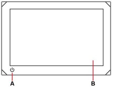 A Power key
- Press and hold to turn the unit on or off.
- Press once to display the quick access menu. Repeat short presses to toggle through the default screen brightness levels.
B Touchscreen
Connectors
7″ unit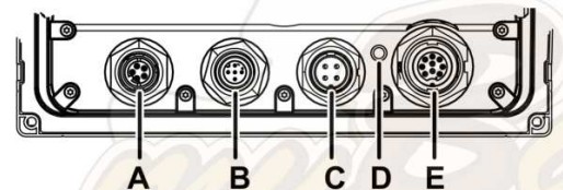 9″, 12″ and ultrawide units
 A Ethernet (5-pin connector)
B NMEA 2000 (Micro-C connector)
C Power and power control (4-pin connector)
D Grounding terminal
E Echosounder (9-pin connector)
F USB (Type-A connector)
Card reader
 A microSD card can be used to:
- Provide detailed charts
- Update software
- Transfer user data (waypoints, routes, tracks, screenshots).
![]() Notes:
Notes:
- If a microSD card and USB storage device are both inserted, by default, data and screenshots are saved to the USB storage device.
- Do not download, transfer or copy files to a chart card as it can damage chart information on the card.
- MicroSD cards up to a maximum of 256 GB capacity are supported in FAT32, ExFAT or NTFS file system.
- Always shut the protective cover securely after or keep watertight.
INSTALLATION
General mounting guidelines
![]() WARNING: Do not install the unit in a hazardous/flammable atmosphere. Always wear appropriate eye wear, ear protection and dust mask when drilling, cutting, or sanding. Remember to check the reverse side of all surfaces whenever drilling or cutting.
WARNING: Do not install the unit in a hazardous/flammable atmosphere. Always wear appropriate eye wear, ear protection and dust mask when drilling, cutting, or sanding. Remember to check the reverse side of all surfaces whenever drilling or cutting.
Note: Choose a mounting location that will not expose the unit to conditions that exceed the technical specifications.
Mounting location
This product generates heat which must be considered when choosing the mounting location.
Ensure the selected area allows for:
- Cable routing, cable connection and cable support.
- Connection and use of portable storage devices.
Do also consider:
- The free space around the unit to avoid overheating.
- The mounting surface’s structure and strength, with regard to the weight of the equipment.
- Any mounting surface vibration that might damage the equipment.
- Hidden electrical wires that might be damaged when drilling holes.
Ventilation
Inadequate ventilation and subsequent overheating of the unit may cause reduced performance and reduced service life. Ventilation is recommended behind all units that are not bracket mounted.
Ensure cables do not obstruct the airflow.
Examples of enclosure ventilation options, in order of preference, are:
- Positive pressure air from the vessel’s air conditioning system.
- Positive pressure air from local cooling fans (fan required at input, fan optional at outlet).
- Passive airflow from air vents.
Electrical and radio frequency interference
This unit conforms with the appropriate Electromagnetic Compatibility (EMC) regulations. To ensure the EMC performance is not compromised, the following guidelines apply:
- Separate battery used for the vessel engine.
- Minimum 1 m (3 ft) between the device, the device’s cables and any transmitting equipment or cables with radio signals.
- Minimum 2 m (7 ft) between the device, the device’s cables and the SSB radio.
- More than 2 m (7 ft) between the device, the device’s cables and the radar beam.
Compass safe distance
The unit outputs electromagnetic interference that can cause inaccurate readings on a nearby compass. To prevent compass inaccuracy, the unit must be mounted far enough away so the interference does not affect compass readings.
For minimum compass safe distance, refer to the technical specifications table.
Wi-Fi®
It is important to test the Wi-Fi performance before the location of the unit is decided. Construction material (steel, aluminum or carbon) and heavy structures will affect Wi-Fi performance.
The following guidelines apply:
- Select a location with a clear, direct line of sight between Wi-Fi connected units.
- Keep the distance between Wi-Fi® units as short as possible.
- Mount the unit at least 1 m (3 ft) away from equipment that might generate interference.
GPS
It is important to test the GPS performance before the location of the unit is decided. Construction material (steel, aluminum or carbon) and heavy structure will affect GPS performance. Avoid a mounting location where metal obstacles block the view of the sky.
A well-placed external GPS module can be added to overcome poor performance.
A Optimal location (above deck)
B Less effective location
C Not recommended location
![]() Note: Consider the lateral swinging if mounting the GPS sensor high above sea level. Roll and pitch might give false positions and affect the true directional movement.
Note: Consider the lateral swinging if mounting the GPS sensor high above sea level. Roll and pitch might give false positions and affect the true directional movement.
Touchscreen
Touchscreen performance can be affected by the location of the unit. Avoid locations where the screen is exposed to direct sunlight or prolonged rainfall.
Corner clip fitment and removal
Use a flathead screwdriver to gently remove the corner clip. Note: Ultrawide display units do not have corner screws or clips.
Panel mount
Refer to the mounting template for illustrated panel mounting instructions.
Rear mount (ultrawide displays only)
- Using the gasket provided, place the display unit into the dash cutout.
- Use the provided tool to tighten the threaded studs.
- Finger tighten the four threaded studs (provided) into the brass inserts on the back case.
- Place the rear mount brackets over the studs and secure with two thumb nuts per stud, turning them clockwise.
![]() WARNING: Finger tighten only! Do not use any tools to tighten the rear brackets into the display chassis. Using excessive force may damage the back side of the display unit.
WARNING: Finger tighten only! Do not use any tools to tighten the rear brackets into the display chassis. Using excessive force may damage the back side of the display unit.
Gimbal mount
- Position bracket with ample height to tilt the unit and ensure space for knob adjustments on both sides.
- Mark the screw locations using the bracket as a template, and drill pilot holes.
- Screw down the bracket using fasteners suitable for the material you are mounting the bracket on.
- Mount the unit to the bracket using the knobs. Hand tighten only.
![]() Note: The screws shown below are for illustration purposes only. Use fasteners that are suitable for the mounting surface.
Note: The screws shown below are for illustration purposes only. Use fasteners that are suitable for the mounting surface.
WIRING
Wiring guidelines
Don’t:
- Make sharp bends in the cables.
- Run cables in a way that allows water to flow down into the connectors.
- Run the data cables adjacent to radar, transmitter, or large/high current carrying cables or high frequency signal cables.
- Run cables so they interfere with mechanical systems.
- Run cables over sharp edges or burrs.
Do:
- Make drip and service loops.
- Use cable-ties on all cables to keep them secure.
- Solder/crimp and insulate all wiring connections if extending or shortening the cables. Extending cables should be done with suitable crimp connectors or solder and heat shrink. Keep joins as high as possible to minimize the possibility of water immersion.
- Leave room adjacent to connectors to ease the plugging and unplugging of cables.
![]() WARNING: Before starting the installation, turn the electrical power off. If power is left on or turned on during the installation, fire, electrical shock, or other serious injury may occur. Be sure that the voltage of the power supply is compatible with the unit.
WARNING: Before starting the installation, turn the electrical power off. If power is left on or turned on during the installation, fire, electrical shock, or other serious injury may occur. Be sure that the voltage of the power supply is compatible with the unit.
![]() WARNING: The positive supply wire (red) should always be connected to (+) DC with a fuse or a circuit breaker (closest available to fuse rating). For the recommended fuse rating, refer to the technical specifications section of this document.
WARNING: The positive supply wire (red) should always be connected to (+) DC with a fuse or a circuit breaker (closest available to fuse rating). For the recommended fuse rating, refer to the technical specifications section of this document.
Power and power control
The power connector is used for power control and an external alarm.
Power connector details
Unit socket (male)
- DC negative
- Power control
- +12 V DC
- External alarm
Power connection
The unit is designed to be powered by 12 V DC.
It is protected against reverse polarity, under voltage and over voltage (for a limited duration).
A fuse or circuit breaker should be fitted to the positive supply. For the recommended fuse rating, refer to the technical specifications section of this document.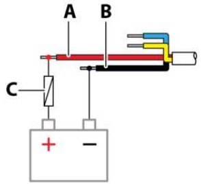 A +12 V DC (red)
B DC negative (black)
C Fuse (for the recommended rating, refer to the technical specifications section of this document)
Power control connection
The yellow wire in the power cable can be used to control how the unit is turned on and off.
Power controlled by power key
The unit will turn on/off when the power key on the unit is pressed. Leave the yellow power control wire disconnected and tape or heat-shrink the end to prevent shorting.
Power control by supply power
The unit will turn on/off without using the power key when power is applied/removed. Connect the yellow wire to the red wire after the fuse.
![]() Note: The unit cannot be powered down by the power key, but can be put in to standby mode (the screen backlight turns off).
Note: The unit cannot be powered down by the power key, but can be put in to standby mode (the screen backlight turns off).
 A Power control (yellow)
Power controlled by ignition
The unit will turn on when the ignition is turned on to start engines.
![]() Note: Engine start batteries and house batteries should have a common ground connection.
Note: Engine start batteries and house batteries should have a common ground connection.
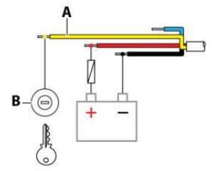 A Power control (yellow)
B Ignition switch
External alarm
Connect the blue wire on the power cable to an external buzzer or siren to trigger an external alarm.
 A External alarm output (blue)
B Siren and relay
C Buzzer
![]() Note: Use a relay for sirens that draw more than 1 A
Note: Use a relay for sirens that draw more than 1 A
NMEA 2000®
The NMEA 2000 data port allows receiving and sharing of data from various sources.
Connector details
Unit socket (male)
- Shield
- NET-S (+12 V DC)
- NET-C (DC negative)
- NET-H
- NET-L
Plan and install an NMEA 2000® network
An NMEA 2000 network consists of a powered backbone from which drop cables connect to NMEA 2000 devices. The backbone needs to run within 6 m (20 ft) of the locations of all products to be connected, typically in a bow to stern layout.
The following guidelines apply:
- The total length of the backbone should not exceed 100 meters (328 ft).
- A single drop cable has a maximum length of 6 meters (20 ft). The total length of all drop cables combined should not exceed 78 m (256 ft).
- A terminator must be installed at each end of the backbone. The terminator can be a terminator plug or a unit with a built-in terminator.
 A NMEA 2000 device
B Drop cable
C Terminator
D Power supply 12 V DC
E Backbone
Power the NMEA 2000 network
The network requires its own 12 V DC power supply, protected by a 3 A fuse.
For smaller systems, connect power at any location in the backbone.
For larger systems, connect power at a central point in the backbone to balance the voltage drop of the network. Ensure the load/current draw on each side of the power node is equal.
![]() Note: 1 LEN (Load Equivalency Number) equals 50 mA current draw.
Note: 1 LEN (Load Equivalency Number) equals 50 mA current draw.
Note: Do not connect the NMEA 2000 power cable to the same terminals as the engine start batteries, autopilot computer, bow thruster or other high-current devices.
USB port
The 9″, 12″, and Ultrawide display units have a USB-A port that can be used to connect a:
- Storage device or
- Card reader
![]() Note: USB devices should be standard PC-compatible hardware.
Note: USB devices should be standard PC-compatible hardware.
Etherne
The Ethernet port(s) can be used for data transfer and synchronization of user-created data. It is recommended that each device in the system is connected to the Ethernet network. No special setup is required for establishing an Ethernet network.
Ethernet connector details
Unit socket
- Transmit positive TX+
- Transmit negative TX-
- Receive positive RX+
- Receive negative RX-
- Shield
Ethernet expansion device
Connection of network devices can be made via an Ethernet expansion device. Additional expansion devices can be added to provide the required number of ports.
Echosounder
Supports:
- Sonar/CHIRP Sonar
- DownScan
- SideScan
- Active Imaging/Active Imaging HD/Active Imaging 3-in-1/TotalScan/StructureScan
![]() Note: A 7-pin transducer cable can be connected to a 9-pin port using a 7-pin to 9-pin adapter cable. However, if the transducer has a paddle wheel speed sensor, the water-speed data will not display on the unit.
Note: A 7-pin transducer cable can be connected to a 9-pin port using a 7-pin to 9-pin adapter cable. However, if the transducer has a paddle wheel speed sensor, the water-speed data will not display on the unit.
Connector details
Unit socket
- Drain/ground
- Not applicable
- Not applicable
- Transducer –
- Transducer +
- Not applicable
- Not applicable
- Temp +
- Transducer ID
SUPPORTED DATA
NMEA 2000® PGN (receive)
| 59392 | ISO Acknowledgement |
| 59904 | ISO Request |
| 60160 | ISO Transport Protocol, Data Transfer |
| 60416 | ISO Transport Protocol, Connection M |
| 65240 | ISO Commanded Address |
| 60928 | ISO Address Claim |
| 126208 | ISO Command Group Function |
| 126992 | System Time |
| 126996 | Product Info |
| 126998 | Configuration Information |
| 127233 | Man Overboard Notification (MOB) |
| 127237 | Heading/Track Control |
| 127245 | Rudder |
| 127250 | Vessel Heading |
| 127251 | Rate of Turn |
| 127252 | Heave |
| 127257 | Attitude |
| 127258 | Magnetic Variation |
| 127488 | Engine Parameters, Rapid Update |
| 127489 | Engine Parameters, Dynamic |
| 127493 | Transmission Parameters, Dynamic |
| 127500 | Load Controller Connection State/Control |
| 127501 | Binary Status Report |
| 127503 | AC Input status |
| 127504 | AC Output Status |
| 127505 | Fluid Level |
| 127506 | DC Detailed Status |
| 127507 | Charger Status |
| 127508 | Battery Status |
| 127509 | Inverter Status |
| 128259 | Speed, Water referenced |
| 128267 | Water Depth |
| 128275 | Distance Log |
| 129025 | Position, Rapid Update |
| 129026 | COG & SOG, Rapid Update |
| 129029 | GNS5 Position Data |
| 129033 | Time & Date |
| 129038 | MS Class A Position Report |
| 129039 | MS Class B Position Report |
| 129040 | MS Class B Extended Position Report |
| 129041 | MS Aids to Navigation |
| 129283 | Cross Track Error |
| 129284 | Navigation Data |
| 129539 | GNSS DOPs |
| 129540 | MS Class B Extended Position Report |
| 129545 | GNSS RAIM Output |
| 129549 | DGNSS Corrections |
| 129551 | GNSS Differential Correction Receiver Signal |
| 129793 | MS UTC and Date Report |
| 129794 | MS Aids to Navigation |
| 129798 | MS SAR Aircraft Position Report |
| 129801 | Cross Track Error |
| 129802 | MS Safety Related Broadcast Message |
| 129283 | Cross Track Error |
| 129284 | Navigation Data |
| 129539 | GN55 DOPs |
| 129540 | GNSS Sats in View |
| 129794 | AIS Class A Static and Voyage Related Data |
| 129801 | MS Addressed Safety Related Message |
| 129802 | MS Safety Related Broadcast Message |
| 129808 | DSC Call Information |
| 129809 | MS Class B “CS” Static Data Report, Part A |
| 129810 | MS Class 8 “CS’ Static Data Report, Part B |
| 130060 | Label |
| 130074 | Route and WP Service • WP List – WP Name & Position |
| 130306 | Wind Data |
| 130310 | Environmental Parameters |
| 130311 | Environmental Parameters |
| 130312 | Temperature |
| 130313 | Humidity |
| 130314 | Actual Pressure |
| 130316 | Temperature, Extended Range |
| 130569 | Entertainment – Current Ale and Status |
| 130570 | Entertainment – Library Data File |
| 130571 | Entertainment – Library Data Group |
| 130572 | Entertainment – Library Data Search |
| 130573 | Entertainment • Supported Source Data |
| 130574 | Entertainment – Supported Zone Data |
| 130576 | Small Craft Status |
| 130577 | Direction Data |
| 130578 | Vessel Speed Components |
| 130579 | Entertainment – System Configuration Status |
| 130580 | Entertainment – System Configuration Status |
| 130581 | Entertainment – Zone Configuration Status |
| 130582 | Entertainment • Zone Volume Status |
| 130583 | Entertainment -Available Audio EQ Presets |
| 130584 | Entertainment – Bluetooths Devices |
| 130585 | Entertainment – Bluetooth• Source Status |
NMEA 2000® PGN (transmit)
| 60160 | ISO Transport Protocol, Data Transfer |
| 60416 | ISO Transport Protocol, Connection M |
| 126208 | ISO Command Group Function |
| 126992 | System Time |
| 126993 | Heartbeat |
| 126996 | Product Info |
| 127237 | Heading/frack Control |
| 127250 | Vessel Heading |
| 127258 | Magnetic Variation |
| 127502 | Switch Bank Control |
| 128259 | Speed, Water referenced |
| 128267 | Water Depth |
| 128275 | Distance Log |
| 129025 | Position, Rapid Update |
| 129026 | COG & SOG, Rapid Update |
| 129029 | GNSS Position Data |
| 129283 | Cross Track Error |
| 129285 | Navigation – Route/WP Information |
| 129284 | Navigation Data |
| 129285 | Route/Waypoint Data |
| 129539 | GNSS DOPs |
| 129540 | GNSS Sats in Yew |
| 130074 | Route and WP Service – WP Ust – WP Name & Position |
| 130306 | Wind Data |
| 130310 | Environmental Parameters |
| 130311 | Environmental Parameters |
| 130312 | Temperature |
| 130577 | Direction Data |
| 130578 | Vessel Speed Components |
DIMENSIONS


TECHNICAL SPECIFICATIONS
| Display | 7 | 9 | 12 | 12 | 15 |
| Resolution (px) | 1024×600 | 1280×720 | 1280 x 800 | 1920 x 720 | 1920 x 720 |
| Brightness | >1000 nits | ||||
| Touchscreen | Full touchscreen (multi-touch) | ||||
| Viewing angles in degrees typrcal value at comrast rato = 10) | 85° (top, bottom, left, and right) | ||||
| Electrical | |||||
| Supply voltage | 12 VDC (10 – 17 VDC min – max) | ||||
| Recommended fuse rating | 2A | 5A | 3A | ||
| Maximum power consumption | 11.50 (833 mA at 13.8) | 18.80 (1362 mAat 138) | 26.2 (1897 mA at 13.8V) | 19.7 (1427 mA at 138) | 28.3W (2050 mA at 13.8V) |
| Protection | Reverse polarity and over-voltage (max 18 V) | ||||
| Environmental | |||||
| Operating temperature range | 15°C to 55°C (S°F to 131°F) | ||||
| Storage temperature | -20°C to 60°C (-4°F to 140°F) | ||||
| Waterproof rating | 1PX6 and IPX7 | ||||
| Shock and vibration | 100,000 cycles of 20G | ||||
| Interface and connectivity | |||||
| GPS | 10 Hz high speed update (internal) WASS, MSAS, EGNOS, GLONASS | ||||
| Wi-Fi | IEEE 802.1.1byg/n | ||||
| Ethernevradar | 1 port (5-pin connector) | ||||
| Echosounder | 1 port (9-pin connector) | ||||
| NMEA 2000″ | 1 port (Micro-C) | ||||
| Data card slot | 1 (microSD*, SDHC) | ||||
| USB | n/a | 1 port (USB-A) Output: 5 VDC, 1.54 | |||
| Physical | |||||
| Weight (display only) | 0.8 kg (1.7 lbs) | 1.2 kg (2.6 lbs) | 2.2 kg (4.9 lbs) | 1.5 kg (3.3 lbs) | 1.9 kg (4.2 lbs) |
| Compass safe distance | 65 cm (2.1 ft) | ||||
 ©2024 Navico Group. All Rights Reserved. Navico Group is a division of Brunswick Corporation.
Reg. U.S. Pat. & Tm. Off, and common law marks.
Visit www.navico.com/intellectual-property to review the global trademark rights and accreditations for Navico Group and other entities.
www.simrad-yachting.com
![]()
Documents / Resources
 | NSX Multifunction Chartplotter |
References
- User Manualmanual.tools