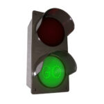
 RGB Rebel Series
Instructions
RGB Rebel Series
RGB Rebel SERIES ![]()
Indoor / Covered Outdoor RGB Sign Install Instructions
Voltage
This sign operates within an input range of 100VAC to 240VAC.
What You Need:
Phillips Head Screw Driver 5/16″ Nut Driver
Appropriate Wall Fasteners Pencil Level
![]() Always turn off the power prior to installation.
Always turn off the power prior to installation.
![]() Be sure any metal debris cleared out of the cabinet.
Be sure any metal debris cleared out of the cabinet.
Installation Steps (Wall Mount)
- Using a 5/16″ nut driver, remove the four bolts retaining the wall mount brackets on the cabinet.
(for mounting other than Wall Mount see the individual Mounting Installation Instructions)
- Mount the wall brackets to the wall surface using appropriate fasteners.
 Slide and secure the sign cabinet to the wall brackets using the hardware removed in step 1.
- With the sign cabinet secured to the wall surface open the front face by removing the two screws retaining the face found on the bottom.

Making your Power Connections
- Bring input power and communications through separate conduit. Weather-proof all connections made through the cabinet.
All power terminations should be made using the provided 5-conductor lever-nuts. (No additional wire nuts required).
 Be sure any metal debris cleared out of the cabinet.
 - Strip the ends of your input wires to 11mm using the guide on the side of one of the lever-nuts.

- To make a connection pull up on the lever of an open port insert wire conductor and push lever back down to lock wire in place.

- You’re done with the electrical! Time to move on to the communications connections.
Power Wiring Guidelines
| Number of Messages | Typical Wire (Lead) Colors |
| Line | Brown |
| Neutral | Blue |
| Earth Ground | Green |
Making your Communications Connection
- With the sign disconnected from power, make the Ethernet connection at the master controller Instructions:

- Choose your connection method; DHCP or Configurable Static IP
To connect using DHCP:
Power on the sign; after 10-15 seconds it will make a request for an IP address from the server
Default DHCP hostname: signaltech
MAC address is provided on a sticker on the side of the sign
Using the included Smart Sign Install Log is recommended for keeping track of your devices
Assign the sign a DHCP reservation
Network Requirements :
Connection Type: Wired Ethernet (CAT5/CAT6)
Network Configuration Options : DHCP (Default) or Configurable Static IP (see step 2 instructions below)
Default Static IP: 192.168.101.45
Primary Communications Port : 10001
Web Interface Port : 80
To connect using a Configurable Static IP address:
Power on the sign and wait for the display to blank out (about 10-15 seconds)
Find the small orange button on the master controller
Press and hold the small orange button (about 5 seconds)
The sign display should then show STATIC, indicating that the sign has been switched to Static IP Mode
Go to 192.168.101.45 in a web browser
Default username/password are blank
Configure your device with desired network settings
It is highly recommended to set a device username and password
Sign Control:
3. Choose your control method; Signal-Tech Sign Control Software or Third-party Control Software
If using Signal-Tech’s Sign Control Software:
Add the sign into the software using its assigned IP address (refer to software manual override in the software)
Note: Sign will not illuminate until it is assigned a schedule or manual override in the software
If using a third-party control software:
Refer to the system’s documentation or contact a representative of the system/software you are using
Refer to our API documentation for interfacing directly with the sign Contact a Signal-Tech representative for information on how to use your sign with a 3rd party system
Warning Statements
![]() Note: Make appropriate wiring connections per local code.
Note: Make appropriate wiring connections per local code.
![]() Note: Any holes drilled into sign cabinet MUST be sealed. Failure to do so may cause a short and void warranty.
Note: Any holes drilled into sign cabinet MUST be sealed. Failure to do so may cause a short and void warranty.
![]() Note: This unit contains a built-in CLASS 2 LED driver.
Note: This unit contains a built-in CLASS 2 LED driver.
![]() Note: This sign is intended to be installed in accordance with the requirements of
Note: This sign is intended to be installed in accordance with the requirements of
Article 600 of the National Electric Code and/or other applicable local codes. This includes proper grounding and bonding of the sign.
![]() WARNING: Risk of Fire or Electric Shock. Do Not interconnect output terminations.
WARNING: Risk of Fire or Electric Shock. Do Not interconnect output terminations.
Documents / Resources
 |
Signal-Tech RGB Rebel Series [pdf] Instructions RGB Rebel Series, RGB Rebel, Rebel, Rebel Series |


