Shelly WAVE2PMSHUT Z-Wave Shutter Control with Power Measurement
Specifications
- Power supply: 120 V AC, 50/60Hz
- Power consumption: < 0.3 W
- Power measurement (W): Yes
- Max. switching voltage AC: 120 V
- Max. switching current AC: 8 A per channel
- Max. power per channel: 1/3 hp
- Overheating protection: Yes
- Overload protection: Yes
- Distance: Up to 40 m indoors (131 ft.) (depends on local conditions)
- Z-WaveTM repeater: Yes
- CPU: Z-Wave™ S800
- Z-Wave™ frequency bands
- 908.42MHz,
- 912MHz, 920MHz
- Maximum radio frequency power transmitted in frequency band(s): < 25 mW
- Size (H x W x D) 37x42x16 ±0.5 mm / 1.46×1.65×0.63 ±0.02 in
- Mounting: Wall console
- Screw terminals max. torque: 0.4 Nm / 3.5 lbin
- Conductor cross section 0.5 to 1.5 mm² / 20 to 16 AWG
- Conductor stripped length 5 to 6 mm / 0.20 to 0.24 in
- Shell material: Plastic
- Color: Black
- Ambient temperature: -20°C to 40°C / -5°F to 105°F
- Humidity 30% to 70% RH
- Max. altitude 2000 m / 6562 ft.
LEGEND
- Device terminals:
- N: Neutral terminal
- L: Live terminals (120 V AC)
- SW1: Input terminal for switch/push-button UP (open)
- SW2: Input terminal for switch/push-button DOWN (close)
- O1: Output terminal for motor UP (open)
- O2: Output terminal for motor DOWN (close)
- Wires:
- N: Neutral wire
- L: Live wire (120 V AC)
- Button:
- S: S button (Fig. 6)
Packaging contents
Device, user guide, Z-Wave™ DSK label
READ BEFORE USE
This document contains important technical and safety information about the Device, its safe use and installation.
CAUTION!
Before beginning the installation, please read carefully and entirely this guide and any other documents accompanying the device. Failure to follow the installation procedures could lead to malfunction, danger to your health and life, violation of law or refusal of legal and/or commercial guarantee (if any). Shelly Europe Ltd. is not responsible for any loss or damage in case of incor-rect installation or improper operation of this device due to failure to follow the user and safety instructions in this guide.
TERMINOLOGY
Gateway – A Z-Wave™ gateway, also referred to as a Z-Wave™ controller, Z-Wave™ main controller, Z-Wave™ primary controller, or Z-Wave™ hub, etc., is a device that serves as a central hub for a Z-Wave™ smart home network. The term “gateway” is used in this document.
S button – The Z-Wave™ Service button, which is located on Z-Wave™ devices and is used for various functions such as inclusion (adding), exclusion (removing), and resetting the device to its factory default settings. The term “S button” is used in this document.
Device – In this document, the term “Device” is used to refer to the Shelly Qubino device that is the subject of this guide.
ABOUT SHELLY QUBINO
Shelly Qubino is a line of innovative microprocessor-managed devices, that allow remote control of electric circuits with a smartphone, tablet, PC, or home automation system. They work on Z-Wave™ wireless communication protocol, using a gateway, which is required for the configuration of devices. When the gateway is connected to the internet, you can control Shelly Qubino devices remotely from anywhere. Shelly Qubino devices can be operated in any Z-Wave™ network with other Z-Wave™ certified devices from other manufacturers. All mains-operated nodes within the network will act as repeaters, regardless of vendor to increasethe reliability of the network. Devices are designed to work with older generations of Z-Wave™ devices and gateways.
ABOUT THE DEVICE
The Device enables remote control of motorized blinds, roller shutters, venetian blinds, awnings, etc. It measures power consumption of the connected device. It is recom-mended to use only motors with electronic or mechanical limit switches. The motor limit switches must be set cor-rectly before connecting the Device to the motor.
INSTALLATION INSTRUCTIONS
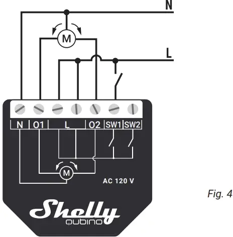
The Device can control a bi-directional AC motor.
It can be retrofitted into standard electrical wall boxes, behind the switches or other places with limited space.
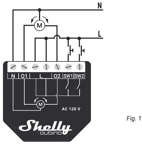
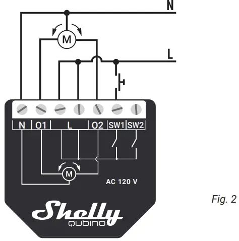
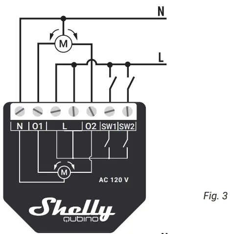
For the installation instructions, refer to the wiring schemes (Fig. 1-5) in this user guide. If you want to use the Device with a push-button, refer to the Fig. 1 and Fig. 2. For a switch, refer to the Fig. 3 and Fig. 4.
- CAUTION! Danger of electrocution. Mounting/installa-tion of the Device to the power grid has to be performed with caution, by a qualified electrician.
- WARNING! Danger of electrocution. Every change in the connections has to be done after ensuring there is no voltage present at the Device terminals.
- CAUTION! Use the Device only with a power grid and appliances that comply with all applicable regulations. A short circuit in the power grid or any appliance connected to the Device may damage it.
- CAUTION! Do not connect the Device to appliances exceeding the given max. load!
- CAUTION! Do not shorten the antenna.
- RECOMMENDATION: Place the antenna as far away as possible from metal elements as they can cause signal interference.
- CAUTION! Connect the Device only in the way shown in these instructions. Any other method could cause damage and/or injury.
- CAUTION! Do not install the Device where it can get wet.
- CAUTION! Do not use the Device if it has been damaged!
- CAUTION! Do not attempt to service or repair the device yourself!
- RECOMMENDATION: Connect the Device using solid single-core cables or stranded cables with ferrules. The cables should have insulation with increased heat resistance, not less than PVC T105°C (221°F).
- CAUTION! Before starting the mounting/installation of the Device, check that the breakers are turned off and there is no voltage on their terminals. This can be done with a phase tester or multimeter. When you are sure that there is no voltage, you can proceed to connect the wires.
- CAUTION! Use only one-phase AC circuit. Do not use mixed AC and DC circuits.
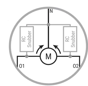
- RECOMMENDATION: For inductive appliances that cause voltage spikes during switching on/off, such as electrical motors, fans, vacuum cleaners and similar ones, RC snubber (0.1 µF / 100 Ω / 1/2 W / 600 V AC) should be connected in parallel to the appliance.
- CAUTION! Do not allow children to play with the push-buttons/ switches connected to the Device. Keep the devices for remote control of Shelly Qubino (mobile phones, tablets, PCs) away from children.
EXTENDED USER GUIDE
For more detailed installation instructions, use cases, and comprehensive guidance on adding/removing the Device to/from a Z-Wave™ network, factory reset, LED signalization, Z-Wave™ command classes, parameters, and much more, refer to the extended user guide at: https://shelly.link/WaveShutter-KB-US
OPERATIONAL INSTRUCTIONS
If the inputs are configured as push buttons:
- Pressing the push-button when the blind is static, moves the blind in the corresponding direction until the endpoint is reached.
- Pressing the push-button for the same direction while the blind is moving stops the blind.
- Pressing the push-button for the opposite direction while the blind is moving reverses the blind movement until the endpoint is reached.
If the inputs are configured as switches:
- Turning the switch on moves the blind in the corresponding direction until the endpoint is reached.
- Turning the switch off stops the blind movement.
- If both switches are turned on, the Device respects the last engaged switch. Turning off the last engaged switch stops the blind movement, even if the other switch is still on.
- To move the blind in the opposite direction, the other switch has to be turned off and on again.
SUPPORTED LOAD TYPES
Inductive with RC Snubber (120 V AC electric motors)
IMPORTANT DISCLAIMER
Z-Wave™ wireless communication may not always be 100% reliable. This Device should not be used in situations in which life and/or valuables are solely dependent on its functioning. If the Device is not recognized by your gateway or appears incorrectly, you may need to change the Device type manually and ensure that your gateway supports Z-Wave Plus™ multi-channel devices.
DISPOSAL & RECYCLING
This refers to the waste of electrical and electronic equip-ment. It is applicable in the US and other countries to collect waste separately.
 This symbol on the product or in the accompanying literature indicates that the product should not be disposed of in the daily waste. Wave Shutter must be recycled to avoid possible damage to the environment or human health from uncontrolled waste disposal and to promote the reuse of materials and resources. It is your responsibility to dispose of the device separately from general household waste when it is already unusable.
FCC NOTES
This device complies with Part 15 of the FCC Rules. Operation is subject to the following two conditions: (1) this device may not cause harmful interference, and (2) this device must accept any interference received, includ-ing interference that may cause undesired operation. The manufacturer is not responsible for any radio or TV interference caused by unauthorized modification or change to this equipment. Such modifications or change could void the user’s authority to operate the equipment. This equipment has been tested and found to comply with the limits for a Class B digital device, pursuant to part 15 of the FCC Rules. These limits are designed to provide reasonable protection against harmful interference in a residential installation. This equipment generates, uses and can radiate radio frequency energy and, if not installed and used in accordance with the instructions, may cause harmful interference to radio communications. However, there is no guarantee that interference will not occur in a particular installation. If this equipment does cause harmful interference to radio or television recep-tion, which can be determined by turning the equipment off and on, the user is encouraged to try to correct the interference by one or more of the following measures:
- Reorient or relocate the receiving antenna.
- Increase the separation between the equipment and receiver.
- Connect the equipment into an outlet on a circuit different from that to which the receiver is connected.
- Consult the dealer or an experienced radio/TV technician for help.
RF exposure statement:
This equipment complies with FCC radiation exposure limits set forth for an uncontrolled environment. The device has been evaluated to meet general RF exposure requirements. The device can be used in portable exposure condition without restriction.
ORDERING CODE: QNSH-001P10US
MANUFACTURER
Shelly Europe Ltd. (former Allterco Robotics EOOD) Address: 51 Cherni Vrah Blvd., building 3, floor 2 and 3, Lozenetz Region, Sofia 1407, Republic of Bulgaria
- Tel.: +359 2 988 7435
- E-mail: zwave-shelly@shelly.cloud
- Support: https://support.shelly.cloud/
- Web: https://www.shelly.com
- Changes in the contact data are published by the Man-ufacturer at the official website: https://www.shelly.com

FAQ
- Q: Can the Device be used with motors that do not have limit switches?
A: It is recommended to use only motors with electronic or mechanical limit switches. The motor limit switches must be set correctly before connecting the Device to the motor. - Q: What is the maximum switching current supported by the Device?
A: The Device supports a maximum switching current of AC 8 A per channel.
Documents / Resources
 |
Shelly WAVE2PMSHUT Z-Wave Shutter Control with Power Measurement [pdf] User Guide 2BDC6-WAVE2PMSHUT, 2BDC6WAVE2PMSHUT, WAVE2PMSHUT Z-Wave Shutter Control with Power Measurement, WAVE2PMSHUT, Z-Wave Shutter Control with Power Measurement, Shutter Control with Power Measurement, Control with Power Measurement, Power Measurement, Measurement, Control |