![]()
![]() Wave Pro Shutter
Wave Pro Shutter
User Guide
Wave Pro Shutter Din Mountable Z Wave Shutter Control With Power Measurement
 |
 |
| Fig. 1 | Fig. 2 |
LEGEND
Device terminals:
N: Neutral terminal
L: Live terminal (110-240 V AC)
SW1: Input terminal for switch/push-button UP (open)
SW2: Input terminal for switch/push-button DOWN (close)
I2: Input terminal for motor DOWN (close)
O1: Output terminal for motor UP (open)
O2: Output terminal for motor DOWN (close)
Wires:
N: Neutral wire
L: Live wire (110-240 V AC)
Button:
S: S button (Fig. 1)
USER AND SAFETY GUIDE
DIN-mountable Z-Wave® shutter control with power measurement
READ BEFORE USE
This document contains important technical and safety information about the Device, its safe use, and installation.
![]() CAUTION! Before beginning the installation, please read carefully and entirely this guide and any other documents accompanying the device. Failure to follow the installation procedures could lead to malfunction, danger to your health and life, violation of the law, or refusal of legal and/or commercial guarantee (if any). Shelly Europe Ltd. is not responsible for any loss or damage in case of incorrect installation or improper operation of this Device due to failure to follow the user and safety instructions in this guide.
CAUTION! Before beginning the installation, please read carefully and entirely this guide and any other documents accompanying the device. Failure to follow the installation procedures could lead to malfunction, danger to your health and life, violation of the law, or refusal of legal and/or commercial guarantee (if any). Shelly Europe Ltd. is not responsible for any loss or damage in case of incorrect installation or improper operation of this Device due to failure to follow the user and safety instructions in this guide.
TERMINOLOGY AND ABBREVIATIONS
Gateway – A Z-Wave® gateway, also referred to as a Z-Wave® controller, Z-Wave® main controller, Z-Wave® primary controller, or Z-Wave® hub, etc., is a device that serves as a central hub for a Z-Wave® smart home network. The term “gateway” is used in this document.
S button – The Z-Wave® Service button, which is located on Z-Wave® devices and is used for various functions such as inclusion (adding), exclusion (removing), and resetting the device to its factory default settings. The term “S button” is used in this document.
Device – In this document, the term “Device” is used to refer to the Shelly Qubino device that is the subject of this guide.
ABOUT SHELLY QUBINO
Shelly Qubino is a line of innovative microprocessor-managed devices that allow remote control of electric circuits with a smartphone, tablet, PC, or home automation system. They work on the Z-Wave® wireless communication protocol, using a gateway, which is required for the configuration of the devices. When the gateway is connected to the internet, you can control Shelly Qubino devices remotely from anywhere. Shelly Qubino devices can be operated in any Z-Wave® network with other Z-Wave® certified devices from other manufacturers. All mains-operated nodes within the network will act as repeaters regardless of vendor to increase the reliability of the network. Devices are designed to work with older generations of Z-Wave® devices and gateways.
WAVE PRO SERIES
Wave Pro series is a line of devices suitable for homes, offices, retail stores, manufacturing facilities, and other buildings. Pro devices are DIN-mountable inside the breaker box and highly suitable for new building construction. All Wave Pro devices can be controlled and monitored through the Z-Wave® network.
ABOUT THE DEVICE
The Device is a DIN rail mountable and enables remote control of motorized blinds, roller shutters, venetian blinds, awnings, etc. It measures the power consumption of the connected device. It is recommended to use only motors with electronic or mechanical limit switches. The motor limit switches must be set correctly before connecting the Device to the motor.
INSTALLATION INSTRUCTIONS
The Device can be DIN-mounted inside the breaker box.
For the installation instructions, refer to the wiring schemes (Fig. 1-2) in this user guide.
![]() CAUTION! Danger of electrocution. Mounting/installation of the Device to the power grid must be performed with caution by a qualified electrician.
CAUTION! Danger of electrocution. Mounting/installation of the Device to the power grid must be performed with caution by a qualified electrician.
![]() CAUTION! Danger of electrocution. Every change in the connections must be made after ensuring there is no voltage present at the Device terminals.
CAUTION! Danger of electrocution. Every change in the connections must be made after ensuring there is no voltage present at the Device terminals.
![]() CAUTION! Use the Device only with a power grid and appliances that comply with all applicable regulations. A short circuit in the power grid or any appliance connected to the Device may damage it.
CAUTION! Use the Device only with a power grid and appliances that comply with all applicable regulations. A short circuit in the power grid or any appliance connected to the Device may damage it.
![]() CAUTION! Do not connect the Device to appliances exceeding the given max. load!
CAUTION! Do not connect the Device to appliances exceeding the given max. load!
![]() CAUTION! Allow at least 10 mm of space around each Pro device if you expect currents higher than 5 A per channel.
CAUTION! Allow at least 10 mm of space around each Pro device if you expect currents higher than 5 A per channel.
![]() CAUTION! Connect the Device only in the way shown in these instructions. Any other method could cause damage and/or injury.
CAUTION! Connect the Device only in the way shown in these instructions. Any other method could cause damage and/or injury.
![]() CAUTION! Do not install the Device where it can get wet.
CAUTION! Do not install the Device where it can get wet.
![]() CAUTION! Do not use the Device if it has been damaged!
CAUTION! Do not use the Device if it has been damaged!
![]() CAUTION! Do not attempt to service or repair the Device yourself!
CAUTION! Do not attempt to service or repair the Device yourself!
![]() CAUTION! Use only a one-phase AC circuit. Do not use mixed AC and DC circuits.
CAUTION! Use only a one-phase AC circuit. Do not use mixed AC and DC circuits.
![]() CAUTION! Before starting the mounting/installation of the Device, check that the breakers are turned off and there is no voltage on their terminals. This can be done with a mains voltage tester or multimeter.
CAUTION! Before starting the mounting/installation of the Device, check that the breakers are turned off and there is no voltage on their terminals. This can be done with a mains voltage tester or multimeter.
When you are sure that there is no voltage, you can proceed to connect the wires.
![]() CAUTION! Do not allow children to play with the push-buttons/switches connected to the Device. Keep the devices for remote control of Shelly Qubino (mobile phones, tablets, PCs) away from children.
CAUTION! Do not allow children to play with the push-buttons/switches connected to the Device. Keep the devices for remote control of Shelly Qubino (mobile phones, tablets, PCs) away from children.
![]() CAUTION! Do not shorten the antenna.
CAUTION! Do not shorten the antenna.
![]() RECOMMENDATION: Place the antenna as far away as possible from metal elements, as they can cause signal interference.
RECOMMENDATION: Place the antenna as far away as possible from metal elements, as they can cause signal interference.
![]() RECOMMENDATION: Connect the Device using solid single-core cables or stranded cables with ferrules. The cables should have insulation with increased heat resistance, not less than PVC T105°C (221°F).
RECOMMENDATION: Connect the Device using solid single-core cables or stranded cables with ferrules. The cables should have insulation with increased heat resistance, not less than PVC T105°C (221°F).
![]() RECOMMENDATION: For inductive appliances that cause voltage spikes during switching on/off, such as electrical motors, fans, vacuum cleaners, and similar ones, an RC snubber (0.1 µF / 100 Ω / 1/2 W / 600 VAC) should be connected in parallel to the appliance.
RECOMMENDATION: For inductive appliances that cause voltage spikes during switching on/off, such as electrical motors, fans, vacuum cleaners, and similar ones, an RC snubber (0.1 µF / 100 Ω / 1/2 W / 600 VAC) should be connected in parallel to the appliance.
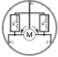
Connect both L terminals to the Live wire and the N terminal to the Neutral wire. Connect the common motor terminal/wire to the Neutral wire. Connect motor direction terminals/wires to the O1 and O2 terminals.
* Connect the first switch/push-button to the SW1 terminal and the Live wire. Connect the second switch/push-button to the SW2 terminal and the Live wire.
*The Device outputs can be reconfigured to match the required rotation direction.
AUTOMATIC CALIBRATION
Automatic calibration is a process during which the Device learns the position of the limit switches.
Note! For the correct position operation, the Device must perform a calibration procedure!
Note! The motor must be equipped with electronic or mechanical limit switches, and the limit positions must be set correctly before calibration!
Note! The calibration is successful when the Device performs a complete cycle of movement: up, down, up, down to 50%.
Note! If the calibration is not executed, check that the limit switches are correctly set and that the wiring is done according to the instructions in the User Guide.
Automatic calibration with the push-button SW1:
Note! Calibration with the push-button SW1 is not time-limited and can be started anytime.
- Move blind to the top (upper) position.
- Press SW1 4 times in 3 seconds.
- The Device will start calibration and complete 3 cycles: down, up, down to 50%.
- Check the LED status to see if the calibration has been successful.
Automatic calibration with the S button:
Note! Calibration with the S button is not time-limited and can be started anytime.
- Enter the Setting mode by pressing the S button for less than 0,5s (short press).
- Keep pressing the S button until the calibration is selected, indicated by the yellow LED colour.
- Start calibration by pressing the S button for more than 2 seconds.
- The Device will start calibration and complete 3 cycles: down, up, down to 50%.
- Check the LED status to see if the calibration has been successful.
VENETIAN MODE
NOTE: For more information about Venetian mode and this Device in general, refer to the Extended User Guide.
EXTENDED USER GUIDE
For more detailed installation instructions, use cases, and comprehensive guidance on adding/removing the Device to/from a ZWave network, factory reset, LED signalization, Z-Wave command classes, parameters, and much more, refer to the extended user guide at: https://shelly.link/WaveProShutter-KB
SPECIFICATIONS
| Power supply | 110-240 V AC, 50/60 Hz |
| Power consumption | < 0.3 W |
| Power measurement (W) | Yes |
| Max. switching voltage AC | 240 V |
| Max. switching current AC | 16 A per channel |
| Overheating protection | Yes |
| Overload protection | Yes |
| Overvoltage protection | Yes |
| Distance | Up to 40 m indoors (131 ft.) (depends on local conditions) |
| Z-Wave® repeater: | Yes |
| CPU | Z-Wave® S800 |
| Z-Wave® frequency bands | 868,4 MHz |
| Maximum radio frequency power transmitted in frequency band(s) | < 25 mW |
| Size (H x W x D) | 94x19x69 ±0.5 mm / 3.70×0.75×2.71 ±0.02 in |
| Weight | 75 g / 2.65 oz. |
| Mounting | DIN rail |
| Screw terminals max. torque | 0.4 Nm / 3.54 lbin |
| Conductor cross-section | 0.5 to 2.5 mm² / 20 to 14 AWG (green connectors) 0.5 to 1.5 mm² / 20 to 16 AWG (white connectors) |
| Conductor stripped length | 6 to 7 mm / 0.24 to 0.28 in (green connectors) 5 to 6 mm / 0.20 to 0.24 in (white connectors) |
| Shell material | Plastic |
| Color | Black |
| Ambient temperature | -20°C to 40°C / -5°F to 105°F |
| Humidity | 30 % to 70 % RH |
| Max. altitude | 2000 m / 6562 ft. |
OPERATIONAL INSTRUCTIONS
If the inputs are configured as push buttons (Fig.1):
- Pressing the push-button when the blind is static moves the blind in the corresponding direction until the endpoint is reached.
- Pressing the push-button in the same direction, while the blind is moving, stops the blind.
- Pressing the push-button for the opposite direction, while the blind is moving, reverses the blind movement until the endpoint is reached.
If the inputs are configured as switches (Fig.2):
- Turning the switch on moves the blind in the corresponding direction until the endpoint is reached.
- Turning the switch off stops the blind movement.
NOTE: This Device does not support the use of two separate ON/OFF switches. It is recommended to use a single double-throw center OFF switch type.
SUPPORTED LOAD TYPES
Inductive with RC Snubber (110-240 V AC electric motors).
IMPORTANT DISCLAIMER
Z-Wave® wireless communication may not always be 100% reliable. This Device should not be used in situations in which life and/or valuables are solely dependent on its functioning. If the Device is not recognized by your gateway or appears incorrectly, you may need to change the Device type manually and ensure that your gateway supports Z-Wave Plus® multi-channel devices.
ORDERING CODE: QPSH-0A1P10XEU
DECLARATION OF CONFORMITY
Hereby, Shelly Europe Ltd. declares that the radio equipment type Wave Pro Shutter complies with Directive 2014/53/ EU, 2014/35/EU, 2014/30/EU, 2011/65/EU. The full text of the EU declaration of Conformity is available at the following internet address: https://shelly.link/WaveProShutter-DoC
For the UP PSTI Act Statement of Compliance, scan the QR code https://shelly.link/compliance-UK
MANUFACTURER:
Shelly Europe Ltd.
Address: 103 Cherni vrah Blvd., 1407 Sofia, Bulgaria
Tel.: +359 2 988 7435
E-mail: zwave-shelly@shelly.cloud
Support: https://support.shelly.cloud/
Web: https://www.shelly.com
Changes in the contact data are published by the Manufacturer at the official website: https://www.shelly.com
V 0.0.1 ![]()
Documents / Resources
 |
Shelly Wave Pro Shutter Din Mountable Z Wave Shutter Control With Power Measurement [pdf] User Guide Wave Pro Shutter Din Mountable Z Wave Shutter Control With Power Measurement, Wave Pro, Shutter Din Mountable Z Wave Shutter Control With Power Measurement, Z Wave Shutter Control With Power Measurement, Power Measurement |