![]()

SGW2828 LoRa Module AT Command
User Manual
Apr 2023 V2.0
SGW2828 LoRa Module AT Command

Introduction
The SGW2828 LoRa Module is a pre-certified SoM enabling LoRa connectivity for portable and extremely low-power embedded systems. The compact, highly sensitive SGW2828 Module easily achieves +30dBm Tx power without the need to integrate an external power amplifier, and is tailored for the US market with an operating frequency of 915MHz and fast frequency hopping abilities. Supporting a wide range of sensors and ultra-long range spread spectrum communication between devices, the SGW2828 Module can be integrated into a variety of popular development platforms to facilitate the building of smart devices fast at optimized cost. 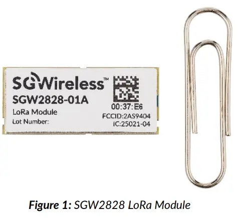 This user manual details the AT command set supported by the SGW2828 LoRa Module.
UART Interface
The SGW2828 Module can be connected via its UART port:
| Baud Rate | 4,800 (default), 9,600, 115,200 |
| Data Bits | 8 |
| Stop Bit | 1 |
| Parity Bit | None |
| Flow Control Settings | Diabled |
AT Commands
Listed in this document are the AT commands supported by the SGW2828 LoRa Module in version V0.0.26
a. Command Set
|
Command List |
AT Command |
Outcome |
| Get Command List | AT? | Get a list of all available AT commands |
| Help Command | AT+<x>? | Get command help information |
| Read Command | AT+<x>=? | Read command |
| Write Command | AT+<x>=<…> | Write command |
| Execution Command | AT+<x> | Execution command |
Notes:
- All commands are case insensitive. All commands end with \r. All returns end with \r\n.
- No spaces should be added when sending commands. If there is a parameter error, it will result in AT_ PARAM_ ERROR. If it is an unrecognized command, it will result in AT_ ERROR. These two error prompts apply to all commands and will not be indicated in the command list going forwards.
b. System Command
|
System Command |
Command |
Response |
|
| 1 | Get firmware version AT+VERSION | Help Command AT+VERSION? | AT+VERSION: Get the firmware version OK |
| Execution Command AT+VERSION=? | SGW2828_EVK_vx.y.z OK | ||
| 2 | Set sleep mode AT+SLEEP Enables ultra-low power consumption sleep mode. After entering sleep mode, the host can send any character through the serial port to wake up the module. Once awakened, it will prompt the “wake up” character. If there is a 32.768KHz crystal oscillator and the function of burning with RTC, the module will wake up by itself after setting the sleep time <t> in the command. |
Help Command AT+SLEEP? | AT+SLEEP: Let the MCU into sleep mode OK |
| Execution Command AT+ SLEEP=<t> Where <t> = sleep time with unit in seconds. Min 1 to max 65,535 seconds. |
Entry sleep | ||
| 3 | Reset MCU AT+RESET |
Help Command
AT+RESET? |
AT+RESET: Trig a reset of MCU OK |
| Execution Command AT+ RESET |
Nil | ||
| 4 | Restore factory settings AT+RELOAD Resets and reloads RF setting information in EEPROM. Default RF Setting: · Preamble: 16 · BW: 250kHz · CR: 1 · SF: 7 · Hop: 0 · Chan: 0 · SX1276 Tx Power: 4dB |
Help Command AT+RELOAD? |
AT+RELOAD: Restore factory settings OK |
| Execution Command AT+ RELOAD |
Preamble:16,BW:250kHz,CR:1,SF:7,Hop:0,chan:0,Pow:4dB OK | ||
| 5 | Get MAC address of module AT+MAC Gets MAC address of module (6 bytes in total). |
Help Command AT+MAC? |
AT+MAC: Get the MAC Value OK |
| Write Command AT+MAC=<Mac Addr> Where <mac addr> is in ASCII format. Example: |
OK |
| Send: AT+MAC=112233aabbcc\r Return: OK\r\n |
|||
| Read Command AT+MAC=? | xx xx xx xx xx xx OK | ||
| 6 | Get ID of STM32 AT+MCUMAC Obtains STM32 96bit UID. |
Help Command AT+MCUMAC? | AT+MAC: Get the STM32 UID OK |
| Read Command AT+MCUMAC=? Where <mac addr> is in ASCII format. Example: Send: AT+MCUMAC=?\r Return: 31 39 47 16 33 36 37 30 32 00 19 00 OK |
xx xx xx xx xx xx xx xx xx xx xx xx OK | ||
| 7 | Set UART speed AT+UARTSPEED |
Read Command AT+UARTSPEED=? |
OK |
| Write Command AT+UARTSPEED=<speed> Where: <Speed> = UART speed (4800, 9600, 115200) Example: Send: AT+UARTSPEED=11520 Return: OK |
c. LoRaP2P
|
|
System Command | Command |
Response |
| 1 | RF Information AT+RF_CONFIG Reads or sets RF Parameters which will be saved to EEPROM. |
Help Command AT+RF_CONFIG? |
AT+RF_CONFIG: Set or read the RF setting OK |
| Write Command AT+RF_CONFIG=<Preamble>,<BW>,<CodeRate>,< SF>,<HopPeriod>, <Channel>,<Power> Where: · <Preamble> = Preamble length · <BW> = Frequency bandwidth – 0: 126 Khz, 1: 250 kHz; 2:500 kHz · <CodeRate> = Error correction rate 1 – 4 · <SF> = Spread spectrum factor 6 – 12 · <HopPeriod> = Frequency hopping period 0 – 255 · <Channel> = RF start channel – 0-127 (bw 125 KHz), 0 – 76 (bw 250 KHz), 0 – 32 (bw 500 KHz) · <Power> = SX1276 RF transmission power -4 ~ 5 dB Remarks: · Received data will only be sent over UART when command is initialized |
OK | ||
| Read Command AT+RF_CONFIG=? |
Preamble:xx,BW: <xx>kHz, SF: <x>, Hop: <x>, Chan: <x>, Pow: <x>dB OK | ||
| 3 | Data received by RF +RX,<Length>,<Data> Reads data received by LoRa RF transmission. |
Data Format +RX,<Length>,<Data> Where: · <Length> = Length of data packet, 1 – 253 · <Data> = Data received in hexadecimal format Remarks: · After device power cycle or reset, LoRa data can only be sent when command AT+RF_CONFIG is initialized. · Ensure both sender and receiver device have the same RF settings when command AT+RF_CONFIG is initialized (Preamble, BW, CodeRate, SF, HopPeriod, Channel and Power). |
Nil |
| 4 | Read RF signal strength AT+RF_RSSI Reads last received data length and RF signal strength from transmitted device. |
Help Command AT+RF_RSSI? |
AT+RF_RSSI: Get last received data Len and RSSI OK |
| Read Command AT+RF_RSSI=? |
Len: xx, RSSI xx dB OK | ||
| 5 | Stop sending RF data AT+RF_STOP Stops RF continuous transmission. RF modules en- ters reception mode. |
Help Command AT+RF_STOP? |
AT+RF_STOP: Stop sending RF data OK |
| Execution Command AT+RF_STOP |
OK | ||
| 6 | Single frequency test AT_TXTONE Tests actual frequency and measures frequency off- set. |
Help Command AT+TXTONE? |
AT+TXTONE: RF Test Tone OK |
d. Module Peripheral Control
|
System Command |
Command |
Response |
|
| 1 | Read or set GPIO high and low level AT+GPIO Reads or sets high or low levels on corresponding pin of module. |
Help Command AT+GPIO? |
AT+GPIO: Read or set GPIO high and low level OK |
| Write Command AT+GPIO=<Pin>,<Level> Where: · <Pin> = Module pin number 8, 16, 17, 23 · <Level> = High and low level of IO port – 0: low level, 1: high level |
GPIO: H/L OK | ||
| Read Command AT+GPIO=?<Pin> |
OK | ||
| 2 | Set I2C communication rate AT+I2C_CONFIG Sends data via LoRa RF transmission. |
Help Command AT+I2C_CONFIG? |
AT+I2C_CONFIG: Set I2C rate OK |
| Write Command AT+I2C_CONFIG=<Rate> Where <Rate> = I2C rate – 1: 5k, 2: 10k, 3: 50K, 4: 100K, 5: 400K Example: Set I2C 10kHz communication rate Send: AT+I2C_config=2 Return: OK |
OK | ||
| Read Command AT+I2C_CONFIG=? |
I2C Frequency:xx OK | ||
| 3 | I2C read and write operations AT+I2C Communicates with external I2C devices. Remove jumper J10 when using I2C command. |
Help Command AT+I2C? |
AT+I2C:set the addr and len,and then to read or writeOK |
| Write Command AT+I2C=<DeviceAddr>,<MemoryAddr>,<Len> Followed by <Data> Where : · <DeviceAddr> = 7bit I2C hardware address · <MemoryAddr> = External memory address – Null: Null memory address, xx: 1Byte memory address, xxxx: 2Byte memory address · <Len> = Length of data in byte to read or write · <Data> = Data to be sent in hex format After sending write command to the module, the serial port will return the symbol ‘>’, and then send data to the module through the serial port. Module will return each byte of the data to host in readable HEX format. Example showing bytes sent to I2C devices: 1. Read data from I2C device AT+I2C=?18,,2 = No memory address, read 2 bytes from 7bit I2C hardware address 0x18 Write data to I2C device AT+I2C=18,12,5 = Write 5 bytes to I2C peripheral with 7bit I2C hardware address, 0x18 and memory address 0x12 2. 1234567890 (data written in hex format) 3. Write data to I2C device AT+I2C=18,1234,5 = Write 5 bytes to I2C peripheral with 7bit I2C hardware address, 0x18 and memory address 0x1234 1234567890 (data written in hex format) Read Command |
OK ·AT_PARAM_ERROR if there is a parameter error. ·Device ERR if I2C peripheral has no ACK. · Time out if no data is sent within 3 seconds of sending write command. <Data> OK |
||
| 4 | Read ad value AT+ADCx Reads ad value of corresponding pin of module. For adc1, change 0 to 1. ADC0 refer to PA0/ADC0 pin on the module, ADC1 refer to PB0/ADC8 pin on the module. Remove jumper J9 when using ADC1 (PB0/ADC8). |
Help Command AT+ADC0? |
AT+ADC0: Get AD0 Value OK |
| Read Command AT+ADC0=? |
AD0: <Value> OK Where <Value> = AD value, 0 – 4,095 |
||
| 5 | Set PWM AT+PWM Sets PWM signal output on 8-pin of module. (PB0) Remove jumper J9 when using PWM. |
Help Command AT+ PWM? |
AT+PWM Set the PWM 1K-10K OK |
| Write Command AT+PWM=<Period>,<Pulse> Where: · <Period> = PWM frequency, 1 – 10 KHz · <Pulse> = PWM duty cycle, 0 – 100% |
PWM Period: xxxx, Pulse: xx OK | ||
| Read Command AT+PWM=? |
PWM Period: xxxx, Pulse: xx OK |
Revision History
|
Revised |
Version |
Description |
| 13-Oct-2020 | 1.0 | Initial document release |
| 17-Dec-2020 | 1.1 | AT Command Module Peripheral Control section update |
| 23-Nov-2021 | 1.2 | Minor format change and AT Command response update |
| 30-Nov-2021 | 1.3 | AT Command ADC/I2C/PWM instruction update |
| 28-Apr-2023 | 2.0 | Firmware and AT Commands updated |
Contact us at cs@sgwireless.com for any queries, or find us at any channel below:
Website: https://sgwireless.com/
LinkedIn: https://www.linkedin.com/company/sgwireless/ Facebook: https://www.facebook.com/sgwirelessIoT Twitter: @sgwirelessIoT
Information in this document is provided solely to enable authorized users or licensees of SG Wireless products. Do not make printed or electronic copies of this document, or parts of it, without written authority from SG Wireless.
SG Wireless reserves the right to make changes to products and information herein without further notice. SG Wireless makes no war- ranty, representation or guarantee regarding the suitability of its products for any particular purpose, nor does SG Wireless assume any liability arising out of the application of any product and specifically disclaims any and all liability, including without limitation consequen- tial or incidental damages. SG Wireless does not convey any license under its patent rights nor the rights of others. SG Wireless products may not be used in life critical equipment, systems or applications where failure of such equipment, system or application would cause bodily injury or death. SG Wireless sells products pursuant to standard Terms and Conditions of Sale which may be found at https://www.sgwireless.com/page/terms.
SG Wireless may refer to other SG Wireless documents or third-party products in this document and users are requested to contact SG Wireless or those third parties for appropriate documentation.
SG Wireless™ and the SG and SG Wireless logos are trademarks and service marks of SG Wireless Limited. All other product or service names are the property of their respective owners.
© 2023 SG Wireless Limited. All rights reserved.![]()
Documents / Resources
 |
SGWireles SGW2828 LoRa Module AT Command [pdf] User Manual SGW2828, SGW2828 LoRa Module AT Command, LoRa Module AT Command, Module AT Command, AT Command, Command |