![]() MRD 7000
MRD 7000
Receiver Decoder Software
User Manual

MRD 7000 Receiver Decoder Software
MRD 7000 – User Manual
Copyright
© 2023 Sencore, Inc. All rights reserved.
3200 Sencore Drive, Sioux Falls, SD USA
www.sencore.com
This publication contains confidential, proprietary, and trade secret information. No part of this document may be copied, photocopied, reproduced, translated, or reduced to any machine-readable or electronic format without prior written permission from Sencore. Information in this document is subject to change without notice and Sencore Inc. assumes no responsibility or liability for any errors or inaccuracies. Sencore, Sencore Inc., and the Sencore logo are trademarks or registered trademarks in the United States and other countries. All other products or services mentioned in this document are identified by the trademarks, service marks, or product names as designated by the companies who market those products. Inquiries should be made directly to those companies. This document may also have links to third-party web pages that are beyond the control of Sencore. The presence of such links does not imply that Sencore endorses or recommends the content on those pages. Sencore acknowledges the use of third-party open-source software and licenses in some Sencore products. This freely available source code can be obtained by contacting Sencore Inc.
About Sencore
Sencore is an engineering leader in the development of high-quality signal transmission solutions for the broadcast, cable, satellite, IPTV, telecommunications, and professional audio/video markets. The company’s world-class portfolio includes video delivery products, system monitoring and analysis solutions, and test and measurement equipment, all designed to support system interoperability and backed by bestin-class customer support.
Sencore meets the rapidly changing needs of modern media by ensuring the efficient delivery of high-quality video from the source to the home.
For more information, visit www.sencore.com.
Revision History
| Date (MM/DD/YYYY) | Version | Description | Author |
| 9/11/2017 | 0.1 | First Draft | JDF |
| 9/14/2017 | 0.2 | Revisions | JDF |
| 9/15/2017 | 1.0 | Initial Release | JDF |
| 11/3/2017 | 1. | Feature Release | JDF |
| 1/3/2018 | 1. | Feature Release | ACD |
| 4/20/2018 | 1. | Feature Release | ACD |
| 5/21/2019 | 1. | Feature Release | BRW |
| 10/3/2019 | 2. | Feature Release | JDF |
| 5/18/2020 | 2. | Feature Release | JDN |
| 5/27/2020 | 2. | Updated Genlock Settings | JDN |
| 5/29/2020 | 2. | Updated Specifications Appendix | ACD |
| 7/7/2020 | 2. | Feature Release | JDN |
| 1/6/2021 | 1.10 | Feature Release | JDN |
| 5/20/2021 | 1. | Feature Release | JDN |
| 3/14/2022 | 1. | Feature Release | JDN |
| 6/21/2022 | 1. | Feature Release | JDN |
| 9/15/2022 | 1. | Feature Release | JDN |
| 11/10/2022 | 1. | Feature Release | BCR |
| 3/10/2023 | 1. | Maintenance Release | JDN |
| 7/27/2023 | 1. | Feature Release | BCR |
| 12/28/2023 | 1. | Feature Release | SJR |
Safety Instructions
- Read these instructions
- Keep these instructions
- Heed all warnings
- Follow all instructions
- Do not use this apparatus near water
- Clean only with dry cloth
- Do not block any ventilation openings. Install in accordance with the manufacturer’s instructions
- Do not install near any heat sources such as radiators, heat registers, stoves, or other apparatus (including amplifiers) that produce heat
- Do not defeat the safety purpose of the polarized or grounding-type plug. A polarized plug has two blades with one wider than the other. A grounding type plug has two blades and a third grounding prong. The wide blade or the third prong is provided for your safety. If the provided plug does not fit into your outlet, consult an electrician for replacement of the obsolete outlet.
- Protect the power cord from being walked on or pinched particularly at plugs, convenience receptacles, and the point where they exit from the apparatus.
- Only use attachments/accessories specified by the manufacturer.
- Unplug this apparatus during lightning storms or when unused for long periods of time.
- Refer all servicing to qualified service personnel. Servicing is required when the apparatus has been damaged in any way, such as power-supply cord or plug is damaged, liquid has been spilled or objects have fallen into the apparatus, the apparatus has been exposed to rain or moisture, does not operate normally, or has been dropped.
- Do not expose this apparatus to dripping or splashing and ensure that no objects filled with liquids, such as vases, are placed on the apparatus.
- To completely disconnect this apparatus from the AC Mains, disconnect the power supply cord plug from the AC receptacle.
- The mains plug of the power supply cord shall remain readily operable.
- Damage Requiring Service: Unplug this product from the wall outlet and refer servicing to qualified service personnel under the following conditions:
o When the power-supply cord or plug is damaged.
o If liquid has been spilled, or objects have fallen into the product.
o If the product has been exposed to rain or water.
o If the product does not operate normally by following the operating instructions. Adjust only those controls that are covered by the operating instructions as an improper adjustment of the controls may result in damage and will often require extensive work by a qualified technician to restore the product to its normal operation.
o If the product has been dropped or damaged in any way.
o The product exhibits a distinct change in performance. - Replacement Parts: When replacement parts are required, be sure the service technician uses replacement parts specified by Sencore, or parts having the same operating characteristics as the original parts. Unauthorized part substitutions made may result in fire, electric shock, or other hazards.
SAFETY PRECAUTIONS
There is always a danger present when using electronic equipment.
Unexpected high voltages can be present at unusual locations in defective equipment and signal distribution systems. Become familiar with the equipment that you are working with and observe the following safety precautions.
- Every precaution has been taken in the design of your product to ensure that it is as safe as possible. However, safe operation depends on you the operator.
- Always be sure your equipment is in good working order. Ensure that all points of connection are secure to the chassis and that protective covers are in place and secured with fasteners.
- Never work alone when working in hazardous conditions. Always have another person close by in case of an accident.
- Always refer to the manual for safe operation. If you have a question about the application or operation email ProCare@Sencore.com
- WARNING – To reduce the risk of fire or electrical shock never allow your equipment to be exposed to water, rain, or high moisture environments. If exposed to a liquid, remove power safely (at the breaker) and send your equipment to be serviced by a qualified technician.
- To reduce the risk of shock the power supply must be connected to a mains socket outlet with a protective earthing connection.
- For the mains plug, the main disconnect should always remain readily accessible and operable.
- When utilizing DC power supply, the power supply MUST be used in conjunction with an over-current protective device rated at 50 V, 5 A, type: Slow-blo, as part of battery-supply circuit.
- To reduce the risk of shock and damage to equipment, it is recommended to ground the unit to the installation’s rack, the vehicle’s chassis, the battery’s negative terminal, and/or earth ground.
![]() Warning: Changes or modifications to this unit not expressly approved by the party responsible for compliance could void the user’s authority to operate the equipment.
Warning: Changes or modifications to this unit not expressly approved by the party responsible for compliance could void the user’s authority to operate the equipment.
Package Contents
The following is a list of the items that are included:
- MRD 7000 Chassis
- MRD 7000 Software
- AC Power Cable
- Breakout or Adapter Cables Depending on Option Modules
- Quick Start Guide
If any of these items were omitted from the packaging, please email ProCare@Sencore.com to obtain a replacement.
Section 1 Overview
1.1 Product Introduction
The new MRD 7000 is designed to be agile, supporting new codecs and video formats through software-based updates versus traditional fixed ASIC hardware design.
The MRD 7000 maintains Sencore’s long tradition of ease of use, with a straight-forward web interface accessible via all major browsers and complete control of the unit.
Support video codecs included HEVC, H.264, MPEG2 and JPEG2000.
Output resolutions and formats include UHD, FHD, HD, and SD applications with 12G- SDI, 6G-SDI, Quad 3G-SDI, 3G-SDI, HD-SDI, SD-SDI, HDMI 2.0a and SMPTE 2110 support.
Every MRD 7000 ships with the software suite pre-loaded on appropriate hardware.
There are optional output configurations that will change the physical connectors available on the back of the chassis.
Input Capabilities:
- 4x ASI
- 4x Satellite
- 2x RJ45 GigE Ethernet Ports
o UDP/RTP MPEG-IP Transport Streams
o Unicast
o Multicast
o SMPTE 2022-7 hitless switching
o FEC - SRT Input
- Zixi Input
- HLS Input
- RTMP Input
- File Input Playback
o .ts and .trp transport stream files
Supported Codecs:
- HEVC/H.265
- MPEG-4/H.264
- MPEG-2
- JPEG 2000
Output Options:
- HDMI 2.0 up to 2160p60
- QUAD 3G-SDI for UHD outputs
- Single-Link
o SD-SDI 480i29.97 & 576i25
o HD-SDI up to 1080p/1080i30
o 3G-SDI up to 1080p60
o 12G-SDI up to 2160p60 - SMPTE 2110
o Dual 25GB SFP28 up to 2160p60
o Dual 10GB SFP up to 1080p60
o Redundant outputs for hitless switching of downstream devices
Power Supply:
- 120/240V Switching Power Supplies
- Redundant power design utilizing two independent cables
1.2 Front Panel Overview
 The MRD 7000 product is a software-based solution; designed to run on a PC server chassis. Initial network configuration is done with keyboard, monitor, and mouse. Once the IP is configured all operation and setup is via web-interface over a network.
To obtain the associated documentation from the server manufacturer or detailed information regarding front of chassis indicator lights email ProCare@Sencore.com
1.3 Rear Panel Overview
The MRD 7000 server has multiple options for the backplane configuration. Both options include dual network ports on the motherboard. Either port can be used to access the web-interface or receive DATA/IP. 
- Breakout connector used for Genlock Input (requires breakout cable)
- Top-left quadrant in Quad Link Mode or 12G/6G/3G/HD-SDI w/ audio in Single Link Mode
- Top-right quadrant of 4K image (or single link copy w/out audio)
- Bottom-left quadrant of 4K image (or single link copy w/out audio)
- Bottom-right quadrant of 4K image (or single link copy w/out audio)
- Eth0: One of two available RJ45 Ethernet ports for management or MPEG/IP
- Eth1: One of two available RJ45 Ethernet ports for management or MPEG/IP
- Local monitor output uses VGA (D-SUB) connector
- Redundant power supplies (120/240 AC Switching PS) VGA and keyboard are only used for setting the network configuration; operation of the device is performed through the web interface
For Single-Link SDI and HDMI 2.0 4K Playback

- Breakout connector used for Genlock Input (requires breakout cable)
- 2x BNC ports for mirrored 12G/6G/3G/HD-SDI w/ embedded audio
- HDMI 2.0 for up to 4K resolutions
- Eth0: One of two available RJ45 Ethernet ports for management or MPEG/IP
- Eth1: One of two available RJ45 Ethernet ports for management or MPEG/IP
- Local monitor output uses VGA (D-SUB) connector
- Redundant power supplies (120/240 AC Switching PS) VGA and keyboard are only used for setting the network configuration; operation of the device is performed through the web interface
For SMPTE 2110 Playback

- Data Path A: One of two SFP ports for SMPTE 2110 uncompressed video over IP
- Data Path B: One of two SFP ports for SMPTE 2110 uncompressed video over IP
- Eth0: One of two available RJ45 Ethernet ports for management or MPEG/IP
- Eth1: One of two available RJ45 Ethernet ports for management or MPEG/IP
- Local monitor output uses VGA (D-SUB) connector
- Redundant power supplies (120/240 AC Switching PS) VGA and keyboard are only used for setting the network configuration; operation of the device is performed through the web interface
For 12G-SDI and HDMI 2.0b Playback

- ASI input port 1
- SDI port 2 for 12G-SDI w/ embedded audio
- Bi-level and tri-level genlock input port
- Eth0: One of two available RJ45 Ethernet ports for management or MPEG/IP
- Eth1: One of two available RJ45 Ethernet ports for management or MPEG/IP
- Local monitor output uses VGA (D-SUB) connector
- Redundant power supplies (120/240 AC Switching PS)
VGA and keyboard are only used for setting the network configuration; operation of the device is performed through the web interface
For 12G-SDI and Quad 3G-SDI Playback and Genlock

- SDI port 1 for 12G-SDI w/ embedded audio. ASI or SD/HD/3G-SDI w/ embedded audio. SDI ports labeled 1 through 4
- Bi-level and tri-level genlock input port
- Eth0: One of two available RJ45 Ethernet ports for management of MPEG/IP
- Eth1: One of two available RJ45 Ethernet ports for management or MPEG/IP
- Local monitor output uses VGA (D-SUB) connector
- Redundant power supplies (120/240 AC Switching PS) VGA and keyboard are only used for setting the network configuration; operation of the device is performed through the web interface
For Decoding 4xASI Input
 4x ASI input ports. ASI ports labeled 1 through 4
- Local monitor output uses VGA (D-SUB) connector
- Eth0: One of two available RJ45 Ethernet Ports for management of MPEG/IP
- Eth1: One of two available RJ45 Ethernet ports for management or MPEG/IP
- Redundant power supplies (120/240 AC Switching PS) VGA and keyboard are only used for setting the network configuration; operation of the device is performed through the web interface
For Decoding 4xSatellite Input

- 4x Satellite input ports. 4xSatellite ports 1 through 4
- Local monitor output uses VGA (D-SUB) connector
- Eth0: One of two available RJ45 Ethernet Ports for management of MPEG/IP
- Eth1: One of two available RJ45 Ethernet ports for management or MPEG/IP
- Redundant power supplies (120/240 AC Switching PS) VGA and keyboard are only used for setting the network configuration; operation of the device is performed through the web interface
For Added IP Input Ports (MRD 70200 IP Card)

- Eth0: One of four available RJ45 Ethernet ports for management or MPEG/IP
- Eth1: One of four available RJ45 Ethernet ports for management or MPEG/IP
- *Eth2: One of four available RJ45 Ethernet ports for management or MPEG/IP
- *Eth3: One of four available RJ45 Ethernet ports for management or MPEG/IP
- Redundant power supplies (120/240 AC Switching PS) VGA and keyboard are only used for setting the network configuration; operation of the device is performed through the web interface
- Slots for Input and Output Cards MRD 70200 IP Card may also be installed here
* NOTE: ETH2 and ETH3 orientation subject to change depending on IP input card location and orientation. Use the virtual front panel detailed in Section 2.4 to reference port identity.
Section 2 Installation
2.1 Rack Installation
The MRD 7000 software product runs on a Supermicro or Dell brand hardware.
Please consult the Supermicro 1028R-WMR(T) Revision 1.0b user manual for complete detail on the rack installation and power cable connections.
https://www.supermicro.com/manuals/superserver/1U/MNL-1723.pdf
Please consult the Dell R340 user manual for complete detail on the rack installation and power cable connections for the Dell server.
https://www.dell.com/support/manuals/en-us/poweredge-r340/per340_ism_pub/
2.2 AC Dual Redundant Power Connections
The Dual Redundant option allows the MRD to be powered by two separate supplies either operating 120V or 240V systems. The power supply will automatically detect the system it is connected to. To hook up the power use the following steps:
- Locate the AC power cords that are included.
- Plug the female end of the power cords (end with no prongs) into the back of the unit.
- Locate a protected outlet (usually inside of the rack) to plug the male ends of the power cables into.
2.3 Maintenance
Refer to the server manufacturer documentation for detailed information regarding server hardware maintenance.
To request a copy of the latest MRD software or release notes from Sencore email ProCare@Sencore.com
2.4 Network Setup via KVM
Connect the VGA (D-SUB) cable to a monitor and a USB keyboard.
The VGA will display the current ethernet settings and provide a text-based menu to configure IP addressing, Subnet Mask, Gateway, and DNS settings.
Sencore recommends configuring the Eth0 port (Leftmost NIC when facing the rear of the unit) be set to a static IP for web-interface access. Ensure the user machine is also on the same network.
For additional information on initial network configuration menu see the Sencore MRD 7000 Quick-Guide documentation. 
Section 3 Web-Interface Operation

3.1 MRD 7000 Web Interface Overview
3.1.1 Logging into the MRD Web Interface
To open the MRD 70000 web interface use one of the following supported browsers and navigate to the unit’s IP address:
- Internet Explorer 7 & above
- Firefox 3.5 & above
- Google Chrome
- Microsoft Edge
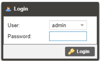
The user will need to login to the web interface. Press the login button to login to the web interface.
Default Credentials
Username: admin
Password: mpeg101
3.1.2 Hiding Unused Inputs
The MRD 7000 web interface allows the user to hide inactive inputs using the ![]() button or show all available inputs by click the
button or show all available inputs by click the ![]() button. Only the selected input will be displayed when unused inputs are hidden.
button. Only the selected input will be displayed when unused inputs are hidden.
3.1.3 Buttons and Status Indicators
When the ![]() icon is shown user configuration is available. Clicking this button will open configuration menus where settings can be changed by the user.
icon is shown user configuration is available. Clicking this button will open configuration menus where settings can be changed by the user. 
When the ![]() icon is shown additional status information can be viewed. Click this button will expand the menu to display the additional status information. All text in status menus shown in ORANGE are user configurable settings. Text shown in BLUE is not user configurable and is strictly a status or value. To minimize the status windows again click the
icon is shown additional status information can be viewed. Click this button will expand the menu to display the additional status information. All text in status menus shown in ORANGE are user configurable settings. Text shown in BLUE is not user configurable and is strictly a status or value. To minimize the status windows again click the ![]() icon.
icon.
Status in the MRD 7000 web interface is shown with LED status indicators:
| Green LED | Status is good. No errors are present, and function is operating normally. | |
| Red LED | Status indicates function is affected by active error. To view the errors, navigate to Alarms panel to view Active Errors. | |
| Grey LED | Status is inactive. Function is currently disabled or unavailable. |
3.2 Decoder Panel
The Decoder panel of the MRD 7000 web interface is used to configure the unit to decode and select the desired output format to use. Each functional piece has a heading: Inputs, Conditional Access, Transport Stream Processing, Decoding, Baseband Processing, and Baseband Output sections are listed from the top down.
 3.2.1 Configuring Active Input
This menu allows the user to configure a primary and backup input. In case there is an input failover the MRD 7000 can detect the failed state and switching to a secondary backup input to provide a continuous output. Which input is primary and backup, how the inputs switchover and restore and switchover timing is all user configurable. Input options include File Input, MPEG/IP Stream 1, MPEG/IP Stream 2, RTMP Input 1, RTMP Input 2, ASI Port 1, ASI Port 2, ASI Port 3, ASI Port 4, SRT Input 1, SRT Input 2,
Seamless RTP, Zixi Input 1, Zixi Input 2, HLS Input 1, HLS Input 2, Satellite Port 1, Satellite Port 2, Satellite Port 3, Satellite Port 4.
Each MPEG/IP Stream Input, SRT Stream Input, Seamless RTP, HLS Input, RTMP Input and Zixi Input can be configured to use either Eth0 or Eth1 ports on the back of the chassis.
Each Satellite Input and ASI Input will follow the physical ports which the name displays in the Web GUI
Input File can play a stored .TS or. TRP transport stream file by uploading to the MRD 7000 internal storage. Files on the MRD 7000 are managed via FTP(S); FileZilla or other apps that support FTP(S) may be used to upload or download capture files. 
| Setting | Range | Description |
| Primary Input | File Input MPEG/IP Stream 1 MPEG/IP Stream 2 ASI Port 1-4 RTMP Input 1 RTMP Input 2 SRT Input 1 SRT Input 2 Seamless RTP HLS Input 1 HLS Input 2 Zixi Input 1 Zixi Input 2 Satellite Port 1-4 None |
Used for both normal operation and input failover settings. During normal operation this input will be the active input. |
| Backup Input | File Input MPEG/IP Stream 1 MPEG/IP Stream 2 ASI Port 1-4 RTMP Input 1 RTMP Input 2 SRT Input 1 SRT Input 2 Seamless RTP HLS Input 1 HLS Input 2 Zixi Input 1 Zixi Input 2 Satellite Port 1-4 None |
During failover operation this input will become the active input. The catalyst for what causes the unit to switch to this input is configured in the following setting. |
| Switch On | Manual Only TS Sync Loss Decode Failure |
Manual Only: the unit will not switch inputs automatically. The user must manually switch inputs. TS Sync Loss: the MRD 7000 will switch from the primary to the backup input if the primary stream loses synchronization for the duration of the Switchover Interval. Decode Failure: the unit will switch to the backup input when it encounters decoding errors on the primary input. |
| Restore On | Manual Only Primary Input TS Restored Backup Input TS Sync Loss Decode Failure |
Manual Only: the unit will not restore to the primary input automatically. The user must manually switch inputs. Primary Input TS Restored: the MRD 7000 restores to primary when the Primary input regains transport stream synchronization. Backup Input TS Sync Loss: the unit will switch from backup to primary when the backup stream loses synchronization for the duration of the Switchover interval. Decode Failure: the unit restores to the Primary Input when the Backup Input experiences a decoding error. |
| Switchover | 1-20 seconds | The time in seconds which Switch On or Restore On value must remain in the configured state before the MRD 7000 switches between the Primary Input and Backup Input or vice versa. |
3.2.1.1 Configuring MPEG/IP Inputs
When either MPEG/IP streams are selected as the active input click on the IP address and gear icon should be visible. Clicking on the gear allows the user to configure the desired input port and network destination parameters. 
| Setting | Range | Description |
| Receive | Enabled Disabled |
This setting allows the user to enable or disable these input stream settings. |
| Physical Connector | Eth0 Eth1 |
The physical connector on the MPEG/IP card that will be used to receive the input. |
| Mode | Multicast Unicast |
Multicast setting allows the unit to receive multicast streams. Multicast streams originate from the IP range 224.0.0.0 –239.255.255.255. Unicast allows the unit to receive unicast streams. Unicast streams originate directly from a source device. |
| Destination IP | 224.0.0.0 – 239.255.255.255 | This setting is only available when receiving a multicast stream. This address is the IP address the source device is receiving from. |
| Destination Port | 0 – 65535 | This is the UDP port the source device is receiving from. This is the only setting required to receive a unicast stream. |
| FEC | Disabled Enabled |
Enabling FEC (Forward Error Correction) tells the MRD 7000 to look at Destination Port +2 and Destination Port +4 for a SMPTE 2022 FEC Matrix. |
| IGMP Filter Mode | Exclude Include |
Used on networks supporting IGMPv3. If this setting is set to Exclude any streams originating from the user defined IP addresses will be rejected. If this setting is set to Include any streams originating from the user defined IP addresses will be received. |
Once the MRD is locked on an MPEG/IP signal the indicator light on the right will turn green, and the received bitrate is displayed. Sync status, the number of transport stream packets inside the UDP payload, and encapsulation type are shown under Status.
Statistics are displayed representing Out of Order Packets, Duplicate Packets, Lost Packets and Discontinuity in RTP IP streams. These counters can be manual reset using the Reset Counters button. The last reset of these error counters is displayed in a date/time format.
The MRD 7000 can also display the individual Program/Service numbers by clicking on the Table Viewer hyperlink. 
3.2.1.2 Configuring File Input
When File Input is selected as the active input, clicking on the gear icon allows the user to choose source file. 
After Input File has been chosen, user has a possibility to:
- Play

- Stop

- Set Start / Stop End Points.


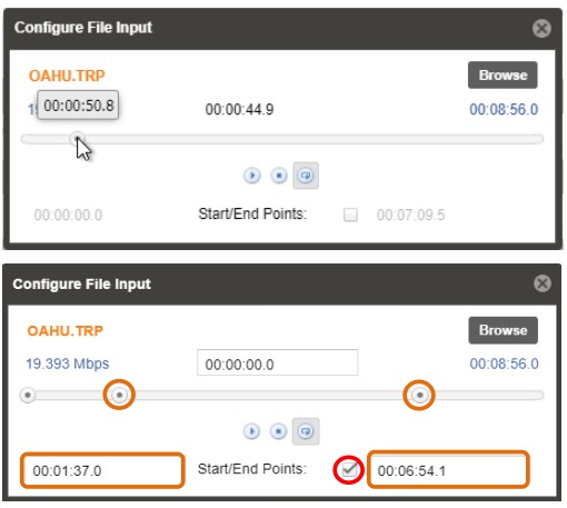 Once the File Input is played out the indicator light on the right will turn green, and the progress bar will be activated
The MRD 7000 can also display the individual Program/Service numbers by clicking on the Table Viewer hyperlink.  3.2.1.3 Configuring ASI Input
When ASI Input is selected as the active input, clicking on the gear icon allows the user to enable/disable ASI ports. 
Once the MRD is locked on ASI signal the indicator light on the right will turn green, and the received bitrate is displayed.
The MRD 7000 can also display the individual Program/Service numbers by clicking on the Table Viewer hyperlink. 3.2.1.4 Configuring SRT Input
When SRT Input is selected as the active input, clicking on the gear icon allows the user to configure SRT dialog.

| Setting | Range | Description |
| Receive | Enabled Disabled | This setting allows the user to enable or disable these input stream settings. |
| Physical Connector | Eth0 Eth1 | The physical connector on the MPEG/IP card that will be used to receive the input. |
| Call Mode | Caller, Listener, Rendezvous | Defines the ‘handshake’ mechanism to be used when establishing connection |
| Remote Host | xxx.xxx.xxx.xxx or URL | Defines the IP address or domain name of the stream on the remote device |
| Remote Port | 1 – 65535 | Defines the port of the stream on the remote device |
| Stream ID | 0 – 512 characters | Defines the receive StreamID when used |
| Local Port Mode | Auto, Manual | In Auto Mode the local port number will be assigned In Manual Mode the local port number will be defined by the user |
| Local Port | 1 – 65535 | Defines the local port number |
| Discovery Timeout (seconds) |
1 – 100, use 0 for infinite | Defines the length of time to wait for the stream to be discovered |
| Passphrase | 10 – 79 characters | Defines the encryption passphrase |
| Latency (ms) | 1 – 8000 | Defines buffer size in milliseconds |
| Remote Port | 1 – 65535 | Defines the port of the stream on the remote device |
| Local Port Mode | Auto, Manual | In Auto Mode the local port number will be assigned In Manual Mode the local port number will be defined by the user |
| Local Port | 1 – 65535 | Defines the local port number |
| Discovery Timeout (seconds) |
1 – 100, use 0 for infinite | Defines the length of time to wait for the stream to be discovered |
| Passphrase | 10 – 79 characters | Defines the encryption passphrase |
| Latency (ms) | 1 – 8000 | Defines buffer size in milliseconds |
Once the MRD is locked on an SRT signal, the indicator light on the right will turn green, and the received bitrate is displayed. Connection state, up time, local port, encryption mode, decryption state, Round Trip Time, Buffer Size, Latency and Link Bandwidth are shown under Status. Statistics are displayed representing number of Reconnections, number of Received Packets, amount of Received Bytes, number of Lost Packets, number of Uncorrected Packets, number of Recovered Packets and SRT NAKs. These
counters can be manual reset using the Reset Counters button. The last reset of these error counters is displayed in a date/time format.
The MRD 7000 can also display the individual Program/Service numbers by clicking on the Table Viewer hyperlink.
 3.2.1.5 Configuring RTP Seamless Input (SMPTE 2022-7)
When RTP Seamless Input is selected as the active input, clicking on the gear icon allows the user to configure RTP Seamless dialog. 
| Setting | Range | Description |
| Physical Connector | Eth0 Eth1 |
The physical connector on the MPEG/IP card that will be used to receive the input. |
| Destination IP | 224.0.0.0 – 239.255.255.255 | This address is the IP address the source device is receiving from. |
| Destination Port | 0 – 65535 | This is the UDP port the source device is receiving from. |
| IGMP Filter Mode | Exclude Include |
Used on networks supporting IGMPv3. If this setting is set to Exclude any streams originating from the user defined IP addresses will be rejected. If this setting is set to Include any streams originating from the user defined IP addresses will be received. |
Once the MRD is locked on an RTP Seamless signals the indicator light on the right will turn green, and the received bitrate is displayed. Sync status, number of active paths, the number of transport stream packets inside the UDP payload, and encapsulation type are shown under Status. For both paths statistics are displayed representing Out of Order Packets, Duplicate Packets, Lost Packets and Discontinuity in RTP IP streams.
These counters can be manual reset using the Reset Counters button. The last reset of these error counters is displayed in a date/time format.
The MRD 7000 can also display the individual Program/Service numbers by clicking on the Table Viewer hyperlink. 3.2.1.6 Configuring Zixi Input
When Zixi Input is selected as the active input, clicking on the gear icon allows the user to configure Zixi dialog. 
| Setting | Range | Description |
| Receive | Enabled Disabled |
Enable/Disable the Zixi Input |
| Physical Connector | Eth0 Eth1 |
The physical Ethernet connector on which to receive the Zixi traffic |
| Remote Host | xxx.xxx.xxx.xxx or URL | The IP address or domain name of the remote host broadcaster |
| Alternate Remote Host | xxx.xxx.xxx.xxx or URL | The alternate IP address or domain name of the remote host broadcaster |
| Remote Port | 1 – 65535 | Defines the port of the stream on the remote device |
| Stream ID | Specified by Zixi broadcaster | Zixi stream ID |
| Password | 1 – 128 characters | Password to protect the stream. |
| Ignore TLS Certificate Error | Ignore Do Not Ignore |
Zixi Ignore TLS Certificate Error |
| Maximum Latency | 30 – 10000 ms | Maximum latency or buffer size in milliseconds |
| Decryption Mode | Disabled AES-128 AES-192 AES-256 Automatic |
Select the type of Decryption Mode |
| Decryption Key | User entry *AES-128 = 32 characters *AES-192 = 48 characters *AES-256 = 64 characters |
Provides the key to allow signal processing if decryption is to be done. |
| FEC Overhead | 0 – 50% | Defines the amount of processing overhead to be used to accommodate FEC |
Once the MRD is locked on a Zixi signal the indicator light on the right will turn green,
and the received bitrate is displayed. Connection state, up time, local port, decryption state, Round Trip Time, Jitter are shown under Status. Statistics are displayed representing number of Reconnections, number of Received Packets, amount of Received Bytes, Dropped Packets, Not Recovered Packets, Not Recovered Packets, FEC Packets, FEC Recovered Packets, ARQ Packets, ARQ Recovered Packets, ARQ Duplicate Packets, ARQ Requests. These counters can be manually reset using the Reset Counters button. The last reset of these error counters is displayed in a date/time format.
The MRD 7000 can also display the individual Program/Service numbers by clicking on the Table Viewer hyperlink.  3.2.1.7 Configuring Satellite Input
Only available when the MRD 70191 Satellite Input Module is installed. When Satellite Input is selected as the active input, clicking on the gear icon allows the user to enable/disable Satellite ports. Once the MRD is locked on a Satellite signal, the indicator light on the right will turn green, and the received bitrate is displayed.
The MRD 7000 can also display the individual Program/Service numbers by clicking on the Table Viewer hyperlink. 3.2.1.8 Configuring RTMP Input
When RTMP Input is selected as the active input, clicking on the gear icon allows the user to configure RTMP Input using the pop-up configuration box.

| Setting | Range | Description |
| Receive | Enabled Disabled |
Enable/Disable the RTMP Input |
| Physical Connector | Eth0 Eth1 |
The physical Ethernet connector on which to receive the RTMP traffic |
| Source URL | xxx.xxx.xxx.xxx or URL | The IP address or domain name of the remote host broadcaster |
Once the MRD is locked on a RTMP signal the indicator light on the right will turn green, and the received bitrate is displayed.
The MRD 7000 can also display the individual Program/Service numbers by clicking on the Table Viewer hyperlink.
 3.2.1.9 Configuring HLS Input
When HLS Input is selected as the active input, clicking on the gear icon allows the user to configure HLS Input using the pop-up configuration box. 
| Setting | Range | Description |
| Receive | Enabled Disabled |
This setting allows the user to enable or disable these input stream settings. |
| Physical Connector | Eth0 Eth1 |
The physical connector on which to receive the HLS traffic. |
| HLS Mode | Pull | Sets HLS to receive through a network location. |
| HLS Network Location | XXX.XXX.XXX.XXX or URL | Defines address of the HLS stream to be received. |
| Decryption Mode | Disabled AES128 |
Defines if a decryption of the received signal is needed, AES 128 standard |
| Decryption Key | User Entry | Provides the key to allow signal processing if decryption is to be done |
| Discovery Timeout | 0 (infinite) 1 – 100 (seconds) |
Defines the length of time to wait for the stream to be discovered |
Once the MRD is locked on an HLS signal the indicator light on the right will turn green, and the received bitrate is displayed. The Encryption Mode is shown under Status.
Configurations are displayed representing the Profile and Discovery Timeout.
The MRD 7000 can also display the individual Program/Service numbers by clicking on the Table Viewer hyperlink. 3.2.2 Configuring Conditional Access
This section will describe how to configure descrambling in the MRD 7000. The MRD 7000 allows descambling of BISS1 and BISS2.
3.2.2.1 BISS1 Descrambling
This menu allows the user to configure BISS descrambling. 12 unique BISS keys can be entered. Clicking on the gear icon allows the user to configure BISS1.

| Setting | Range | Description |
| Operation Mode | Enabled Disabled | Enable / Disable BISS descrambling |
| Selected Key | Key 1 – 12 | Select a key to configure |
| Alias | 16 characters | Set an Alias for the selected key |
| Mode | Mode 1 Mode E | This setting sets the Mode of the BISS key that has scrambled the transport stream. |
| Mode 1 Session Word | N/A | If Mode 1 is selected the user enters the BISS session word here. |
| Mode E Session Word | N/A | If Mode E is selected the user enters the BISS session word here |
| Mode E Injected ID | N/A | If Mode E is selected the user enters the BISS injected ID here. |
3.2.2.2 BISS2 Descrambling
This menu allows the user to configure BISS descrambling. 12 unique BISS keys can be entered. Clicking on the gear icon allows the user to configure BISS2.
| Setting | Range | Description |
| Operation Mode | Enabled Disabled | Enable / Disable BISS descrambling |
| Selected Key | Key 1 – 12 | Select a key to configure |
| Alias | 16 characters | Set an Alias for the selected key |
| Protocol | BISS 1 BISS 2 |
Select which mode of BISS descrambling |
| Mode | Mode 1 Mode E Mode CA | This sets the Mode of the BISS key that has scrambled the transport stream. |
| Mode 1 Session Word | N/A | If Mode 1 is selected the user enters the BISS session word here. |
| Mode E Session Word | N/A | If Mode E is selected the user enters the BISS session word here |
| Mode E Injected ID | N/A | If Mode E is selected the user enters the BISS injected ID here |
| Mode CA Key Pair | Buried Injected | If Mode CA is selected the user will then select the type of conditional access. Buried or Injected |
| Mode CA Public Key | Download | If Mode CA Buried is selected, the user can download the Public Key from the MRD 7000. The file will be generated as a .pub |
| Mode CA Private Key | Upload | If Mode CA Injected is selected, the user will need to upload the Private Key. The file name length must be less than 20 characters. The supported file types are .txt or .priv |
3.2.3 Configuring Transport Stream Processing
Setting Heartbeat timeout will determine the time in minutes between SCTE35 messages before the MRD 7000 will report an error. Timeout can be configured in the following way: 3.2.4 Configuring Decoding and Service Selection
This menu allows the user to configure which service the MRD 7000 will decode. There are two editable fields in this menu. 
| Setting | Range | Description |
| Mode | Auto Seek Service Lock | The MRD will decode the first service found Locks the decoder to defined service number |
| Service Number | # | Click the drop-down to select a service number. This list will be populated by all services in the incoming transport stream. This will also include the Service Name and the Service Type. |
When the MRD 7000 begins decoding a service, the Additional Data status will report HDR metadata, SMPTE 2038, Closed Captions, SCTE35 and Subtitles presence.  3.2.4.1 Advanced Configuration
This section allows the user to configure advanced settings of the MRD 7000.
Parallel Frame Processing allows the user to tune the decode latency of the MRD 7000.
Lower Parallel Frames results in lower latency. Setting these values too low can result in dropped video frames. Default settings are recommended unless minimal latency is crucial to the application.
Clicking the Restore Defaults button will reset all values to the default values. 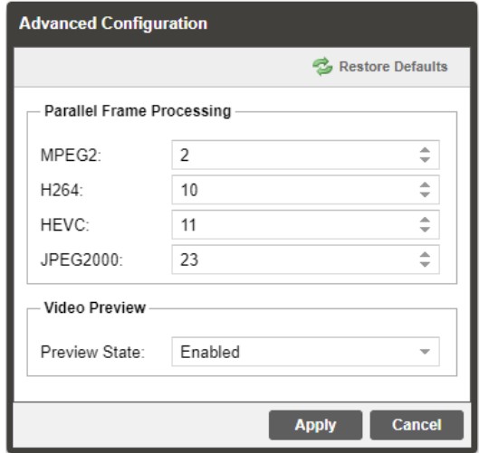
| Setting | Range | Description |
| MPEG2 | 1-50 | The parallel frames processed when decoding MPEG2 video. |
| H264 | 1-50 | The parallel frames processed when decoding H264 video. |
| HEVC | 1-50 | The parallel frames processed when decoding HEVC video. |
| JPEG2000 | 1-50 | The parallel frames processed when decoding JPEG2000 video. |
| Preview State | Enabled/Disabled | Enabling the Preview State will cause the MRD 7000 to display a thumbnail in the Decoding section. |
3.2.5 Configuring Baseband Processing
The section of the main tab allows the user to configure the video, audio, and genlock baseband processing.
3.2.5.1 Configuring Video Baseband Processing
The Configure Video menu is opened by clicking on the gear icon just under the Baseband Processing section title.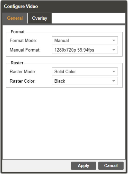
| Setting | Range | Description |
| Format Mode | Auto Manual |
The MRD will match output format to input MRD uses specified Manual Format value |
| Manual Format | 3840x2160p 60fps 1280x720p 59.94fps |
Refer to Specification for complete list |
| Raster Mode | Solid Color Last Frame |
Selected color outputs if no input is locked Last decoded frame is shown when no input |
| Raster Color | Black White Yellow Cyan Magenta Red Blue Green Gray | Choose color to display when raster mode is set to Solid Color |

| Setting | Range | Description |
| Overlay Type | None Teletext Subtitles DVB Subtitles Closed Caption |
Select subtitle overlay type |
| Teletext Subtitles | 100 to 8FF | Select Teletext page for Overlay |
| DVB Subtitles | Language Codes | Select Subtitles for Overlay |
| Closed Caption | NTSC DTVCC |
Select subtitle overlay CC type |
| NTSC Service | CC1–CC4 | Select subtitle overlay NTSC type |
| DTVCC Service | SERVICE 1–SERVICE 6 | Select subtitle overlay DTVCC type |
3.2.5.2 Configuring Audio Baseband Processing
The audio menu allows the user to configure the audio processing mode (decode / discrete) settings of the MRD 7000. Up to 8 audio PID’s inside of the decoded service can be processed.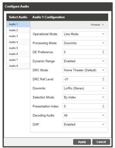 The configured settings are displayed when expanding the audio status by clicking the + button.
| Setting | Range | Description |
| Operational Mode | Line Mode RF Mode Custom 1 Custom 0 |
This setting allows the user to select the audio compression Monitor mode |
| Processing Mode | Downmix Discrete | Downmix will convert the full PID (be it 3/2 or 2/0) to Lt/Rt Stereo. Discrete is part of configuration for Surround Sound Decoding and Embedding (refer to Section 3.2.6.2, Configuring SDI Audio, for more details) |
| DE Preference | -12 to 12 | Set the gain in dB to be applied to the dialog components in the signal |
| Dynamic Range | Enabled Disabled | Use dynamic range for AC-3 and AC-4 downmix. |
| DRC Mode | Home Theater (Default) Flat Panel Portable – Headphones Portable – Speakers |
AC-4 audio mode of Dynamic Range Control. The different modes allow for different levels of audio. |
| DRC Ref Level | -31 to -27 -26 to -17 -16 to -7 -16 to -7 |
Dynamic Range Control reference level for AC-4 audio. This following audio level ranges correlate to the mode of AC-4 audio selected. |
| Downmix | Lo/Ro (Stereo) Lt/Rt (Dolby Surround) Lt/Rt (Auto) Dual Mono/Stereo Dual Left Dual Right Head Phone Speaker Virt |
When the audio is downmixed in the MRD 7000 two audio channels are created. The channels can be configured using the settings available in the drop-down menu. |
| Selection Mode | Preference Based By Index | The AC-4 audio presentation stream mode can be set to Preference Based or By Index. Preference Based selects the first available audio presentation stream and By Index allows the user to select which audio presentation stream to begin decoding. |
| Presentation Index | 0-100 | The first decoded AC-4 audio presentation stream can by selected by entering the index number of that stream. |
| Decoding Audio | All Main Associate |
The type of AC-4 audio can be set to All, Main, or Associate. Main and Associate audio contain different content such as music, effects, scene descriptions or director’s comments. |
| DAP | Enabled Disabled |
Dolby Audio Processing can be enabled or disabled with this setting. |
3.2.5.3 Configuring Genlock Processing
The Genlock menu allows the user to configure Horizontal Offset Pixels. The configure menu is opened by clicking on the gear icon. Genlock status is reported as Locked/Unlocked (reference source enabled) or N/A (refence source disabled) and Mode status.
3.2.6 Configuring Baseband Output
This menu allows the user to configure the SDI output settings for the MRD 70130, MRD 70140, MRD 70141, and MRD 70150 modules.
3.2.6.1 Configuring SDI Video
The MRD 7000 comes with the ability to decode SDI Level A or SDI Level B, to disable the SDI in an error state, and to set the Quad link mode. The MRD 70140 and MRD 70141 are the two output cards that support SDI disabling. The MRD 70140 and 70141
modules can select Two Sample Interleave or Square Division for the SDI Link Mode when they are configured for Quad 3G-SDI (UHD). Picture below displays how SDI video can be configured depending on the output module. 
General
| Setting | Range | Description |
| Video Loss Mode | Disable SDI Display Raster | Setting to Disable SDI disables the SDI output of the MRD 7000 in case of an error state. Setting to Display Raster the MRD 7000 will display the raster color selected in Section 3.2.5.1 |
Quad Link
| Setting | Range | Description |
| Link Mode | Two Sample Interleave Square Division | This setting changes the SDI link mode. |
| 3G Level | A or B | This setting changes the SDI output level. |
| SMPTE Standard: | SMPTE ST 425-1 SMPTE ST 425-5 |
SMPTE ST 425-1: The Quad Link SDI output will follow SMPTE ST 425-1 mapping. This mapping format is generally designated as legacy formatting. SMPTE ST 425-5: The Quad Link SDI output will follow SMPTE ST 425-5 mapping. This mapping format is generally designated as standard formatting. |
3.2.6.2 Configuring SDI Audio
This menu allows the user to configure the SDI embedded audio settings. Each decoder on the MRD 7000 can decode and output up to eight embedded SDI audio pairs. Eight audio pairs can be embedded into four Group Pairs. Each Group Pair may be set for
PCM Mode (either downmixed or discrete decode), Passthrough Mode (compressed Dolby E, Dolby ATMOS) or Auto Mode.
This menu will interact differently depending upon which options are chosen for the “Mode” section (PCM, Passthrough, Auto). This section will also cover two distinct PCM configurations for either Stereo Downmix or Discrete Surround Sound decode that interact with the “Processing Mode” option from Section 3.2.5.2, Configuring Audio Baseband Processing.
Overview of Audio Menu
After clicking the Gear Icon next to “SDI” choose the “Audio” tab to expose settings for the individual SDI Group Pairs as shown below 
Select Pair
| Setting | Range | Description |
| Select Pair | Group 1 Pair 1 Group 1 Pair 2 Group 2 Pair 1 Group 2 Pair 2 Group 3 Pair 1 Group 3 Pair 2 Group 4 Pair 1 Group 4 Pair 2 |
Each Group/Pair combination represents a different physical pair on the embedded SDI Audio (8 total pairs available). Each physical pair may be assigned to pass a full Stereo Downmix, portion of Discrete Surround or full Compressed Passthrough By default, each physical pair is enabled and set to output PCM Stereo Downmix for the corresponding Audio Source (Audio 1 goes to Group 1 Pair 1, Audio 2 goes to Group 1 Pair 2, and so on). |
After selecting the Group/Pair, that physical pair’s Group M Pair N Configuration will be eligible for Mode and Source Selection.
Group M Pair N Configuration
| Setting | Range | Description |
| Embed | Enabled Disabled | When Enabled, the SDI Physical Pair will output the configured source material. When Disabled, the SDI Physical Pair will output no level. |
| Mode | PCM Pass-through Auto |
PCM will always output the decoded Audio Source as discrete or downmixed (as per “Processing Mode” option from Section 3.2.5.2). Pass-through will always output the compressed Audio Source (from the unmodified input before the decoder). Auto will first read the Audio Source’s CODEC before deciding how to output. Should it detect Dolby E or another undecodable Audio CODEC, the pair will pass-through the audio. Should it detect Dolby Digital or another decodable CODEC, it will decode and output the Decoded PCM audio. |
| Source | Disabled Audio 1 – 8 | Choose the Audio Source to be referenced for output. This field corresponds to the “Select Audio” tab from Section 3.2.5.2. If set to Disabled, the physical pair will output no level. If set to Audio 1 – 8, it will use that source for reference when outputting the compressed or uncompressed audio. |
| Config | Stereo Mono | Only available if “Mode” is set for PCM or Auto. Stereo will enable the “Pair” option under Stereo and output a full stereo pair. Mono will enable the “Left Channel” and “Right Channel” options under Mono. |
| Pair | Lf/Rf C/LFE Ls/Rs Lb/Rb Ch1/Ch2 Ch3/Ch4 Ch5/Ch6 Ch7/Ch8 |
Only available if “Mode” is PCM or Auto and “Config” is Stereo. Select a pair from the sourcing Audio PID to embed on the SDI. If “Processing Mode” (Section 3.2.5.2) for the selected “Source” above is PCM, the output will take the Left-Total/Right-Total of the full PID and output as Stereo regardless of this setting. If the Processing Mode field is Discrete, the output will source the selected pair as part of the Surround Sound output. Later in this section there is a description on configuring Discrete Surround Sound output. |
| Left Channel Right Channel | Disable / Channel 1 – 8 Audio 1 – 8 |
Only available if “Mode” is PCM or Auto and “Config” is Mono. Advanced Audio embedding allows to embed mono audio channels from multiple audio PIDs in the same group/pair, i.e., a user can use mono audio left from Audio 1 and mono audio right from Audio 2 and embed them as Group 1 Pair 1. |
 Available Config Options when “Mode” is set to Pass-through:
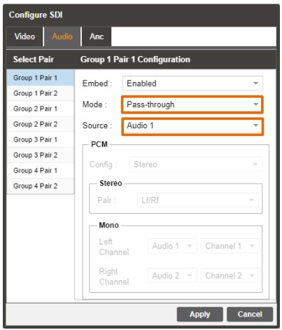
3.2.6.3 Configuring Discrete Surround Decode and Output
Configuring Discrete Decode and output is performed in three main steps:
- Confirm one or more Audio PIDs are receiving at least 3/2.
- Configure the 3/2 Audio PID for Discrete Decode
- Configure the SDI Output to send each of the at least three group/pairs
Confirming one or more Audio PIDs are receiving at least 3/2
After locking to the input and selecting the incoming service, review the “Decoding” status (as per Section 3.2.4). Under Decoding Status, view the available Audios.
For this above example, Audio 1 (PID 52) is eligible for Discrete Surround decode and output, as it is 3/2. Audio 2 (PID 53) is only eligible for Downmix, as it is only 2/0, though it is still capable of PCM stereo or Pass-through.
Configuring the 3/2 Audio PID for Discrete Decode
After confirming which Audio PIDs have 3/2 payload, open the Audio Baseband Processing settings (see Section 3.2.5.2) and select the corresponding Audio. In this sample case, Audio 1 is chosen, as it carries the 3/2. The only necessary setting change is “Processing Mode” as “Discrete”. This ensures the Audio PID is being decoded with splitting the six channels into groups of two for embedded SDI output.
Configuring the SDI Output to Send the Discretely Decoded Pairs Navigate to the SDI Audio configuration (as per Section 3.2.6.2). 

For this sample, each of the first three Group/Pair combinations have the “Source” field configured for “Audio 1”, indicating they all reference the same source PID 52. Each of the three pairs will output a different stereo component of the surround (Lf/Rf goes to
Group 1 Pair 1, C/LFE goes to Group 1 Pair 2 and Ls/Rs goes to Group 2 Pair 1). In this case, as there is PID 53 on Audio 2, Group 2 Pair 2 is simply configured as stereo with downmixed “Audio 2” chosen as the “Source”. 3.2.6.4 Configuring SDI ANC
The Configure SDI menu also allows for the ability to enable or disable ANC data. 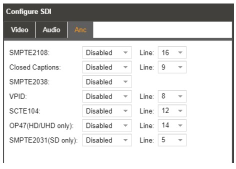
| Setting | Range | Description |
| SMPTE2108 | Enabled Disabled |
This setting enabled SMPTE 2038 embedding on a selected line. |
| Closed Captions | Enabled Disabled |
This setting enables Closed Captions embedding on a selected line. |
| SMPTE2038 | Enabled Disabled |
This setting enables SMPTE 2038 embedding |
| VPID | Enabled
Disabled |
This setting enables VPID embedding on a selected line |
| SCTE104 | Enabled Disabled |
This setting enables SCTE104 embedding on a selected line |
| OP47 | Enabled Disabled |
This setting enables OP47 embedding on a selected line |
| SMPTE2031 | Enabled Disabled |
This setting enables SMPTE2031 embedding on a selected line |
SMPTE 2108 VANC Embedding
The MRD 7000 supports extraction of SMPTE 2108 metadata from the input video PID and embedding in SDI. User configuration is needed for enabling SMPTE 2038 data to be embedded in SDI. Presence of the incoming SMPTE 2108 data is reported in the
Additional Data status in the Decoding section (Transfer Characteristics).
Closed Captions VANC Embedding
The MRD 7000 supports extraction of EIA-608 and EIA-708 subtitles from the input PID and embedding in SDI. User configuration is needed for enabling Closed Captioning data to be embedded in SDI. Presence of the incoming Closed Captioning data is
reported in the Additional Data status in the Decoding section
SMPTE 2038 VANC Embedding
The MRD 7000 supports extraction of SMPTE 2038 metadata from the input video PID and embedding in SDI. User configuration is needed for enabling SMPTE 2038 data to be embedded in SDI. Presence of the incoming SMPTE 2038 data is reported in the
Additional Data status in the Decoding section.
VPID VANC Embedding
The MRD 7000 supports extraction of VPID metadata from the input video PID and embedding in SDI. User configuration is needed for enabling VPID data to be embedded in SDI.
SCTE35/104 VANC Embedding
The MRD 7000 extracts SCTE 35 messages from the transport stream then converts them to SCTE104 messages and embeds them as VANC packets on the SDI output.
User configuration is needed for enabling SCTE104 data to be embedded in SDI.
Presence of the incoming SCTE35 data is reported in the Additional Data status in the Decoding section.
OP47 VANC Embedding
The MRD 7000 supports extraction of OP47 subtitles (UHD/HD) from the input PID and embedding in SDI. User configuration is needed for enabling OP47 data to be embedded in SDI. Presence of the incoming OP47 data is reported in the Additional
Data status in the Decoding section
SMPTE2031 VANC Embedding
The MRD 7000 supports extraction of SMPTE2031 subtitles (SD only) from the input PID and embedding in SDI. User configuration is needed for enabling SMPTE2031 data to be embedded in SDI. Presence of the incoming SMPTE2031 data is reported in the
Additional Data status in the Decoding section.
3.2.6.5 Configuring SMPTE 2110 Path 1 and Path 2
This menu allows the user to configure the SMPTE 2110 output settings. The MRD 7000 comes with the ability to configure two separate paths for SMPTE 2110. Also, with SMPTE 2110 is the ability to configure eight audio pairs. Video, Audio 1-8, and Data Streams are all configurable to enable or disable the output, set Destination IP, and Destination Port. 
| Setting | Range | Description |
| Audio Conformance Level | Level A Level B Level C | The user may select the desired audio conformance level for the 2110 output. Level A conformance consists of 1 to 8 audio channels with a packet time of 1 ms Level B conformance consists of 1 to 8 audio channels with a packet time of 125 μs or 1 ms Level C conformance consist of 1 to 16 audio channels with a packet time of 125 μs and of 1 to 8 audio channels with a packet time of 125 μs. |
| Audio Packet Duration | 125 us 1 ms | This selection will change the arrival delay of the 2110-30 audio flow. The 2110-30 audio flows can have a delay of 125 μs or 1 ms depending on the conformance level. If Level A conformance is selected, the audio packet timing will default to 1 ms. When configured to Level B or Level C audio conformance, the user may select 125 μs or 1 ms for the duration. A 125 μs Audio Packet Duration allows up to 8 pairs of audio to be active per 211-30 flow. A 1 ms Audio packet duration allows up to 4 pairs of audio to be active per 2110-30 flow. |
| Output | Enabled Disabled |
This setting allows the user to enable or disable the output. |
| Destination IP | 224.0.0.0 – 239.255.255.255 | This setting allows a user to configure the output destination IP address. |
| Destination Port | 0-65535 | This is the UDP port the source device is sending to. |
| Payload ID | 96 – 127 | The RTP payload ID specifies the value for the RTP packet header. The value distinguishes between video, audio, and ancillary data for 2110. The default values are 96 for 2110-20, 97 for 2110-30, and 100 for 2110-40. |
3.2.6.6 Configuring SMPTE 2110 Video
This tab can be used to configure the output’s video behavior in the event of loss of input or other failure to decode.
| Setting | Range | Description |
| Video Loss Mode | Disable ST 2110 Display Raster | When set to Disable ST 2110, if the video fails to decode, this will cease all outbound IP bitrate from the 2110 card on both paths (Video, Audio and Anc). When set to Display Raster, the MRD 7000 will continue to output bitrate and the video will display the raster color selected in Section 3.2.5.1 |
3.2.6.7 Configuring SMPTE 2110 Audio
This menu allows the user to configure the SMPTE 2110 embedded audio settings. The MRD 7000 comes standard with the ability to handle up to eight audio services. Eight audio pairs can be embedded to contain a PCM (either downmixed or discrete decode).
In the case where a discrete audio pair is being embedded, the channel pair in the column must be selected. For audio services that indicate the specific channels (Lf, Rf, C, Ls, Rs, LFE) the user can select the audio channels to assign to an output using the
named discrete options. The following audio formats identify specific channels: Dolby Digital, Dolby Digital Plus, AAC-LC, HE-AAC. If the specific channels are not identified (LPCM Audio for example) than the user can use the multi-channel audio service to
select the channel pair of the audio service to output. When the user has selected a named discrete option without identifying the audio channels in the service, the unit will output Ch1/Ch2 (if present) if Lf/Rf is chosen, Ch3/Ch4 (if present) if C/LFE is chosen
and Ch5/Ch6 (if present) if Ls/Rs is chosen.
| Setting | Range | Description |
| Audio Source | Silence Audio 1-8 Disabled | Silence: the given audio pair on the stream will output bitrate as audio silence data. Audio 1~8: The user may select the desired audio source for each embedded audio pair. The number of audio pairs varies depending on Conformance Level and Packet Duration. See Section 3.2.6.5 for additional details. Disabled: no audio pair will be embedded on the stream for this entry. |
| Audio Channels | Lf/Rf C/LFE Ls/Rs Lb/Rb Ch1/Ch2 Ch3/Ch4 Ch5/Ch6 Ch7/Ch8 |
When the audio is downmixed in the MRD 7000 two audio channels are created. The channels can be configured using the settings available in the drop-down menu. Refer to the details above (section 3.2.6.6) for further details. |
3.2.6.8 Configuring SMPTE 2110 Anc
The Configure SMPTE 2110 menu also allows for the ability to enable or disable ANC data. 
| Setting | Range | Description |
| SMPTE2108 | Enabled Disabled |
This setting enabled SMPTE 2038 embedding on a selected line. |
| Closed Captions | Enabled Disabled |
This setting enables Closed Captions embedding on a selected line. |
| SMPTE2038 | Enabled Disabled |
This setting enables SMPTE 2038 embedding |
| VPID | Enabled Disabled |
This setting enables VPID embedding on a selected line |
| SCTE104 | Enabled Disabled |
This setting enables SCTE104 embedding on a selected line |
| OP47 | Enabled Disabled |
This setting enables OP47 embedding on a selected line |
| SMPTE2031 | Enabled Disabled |
This setting enables SMPTE2031 embedding on a selected line |
SMPTE 2108 VANC Embedding
The MRD 7000 supports extraction of SMPTE 2108 metadata from the input video PID and embedding in SDI/IP. User configuration is needed for enabling SMPTE 2038 data to be embedded in SDI/IP. Presence of the incoming SMPTE 2108 data is reported in
the Additional Data status in the Decoding section (Transfer Characteristics).
Closed Captions VANC Embedding
The MRD 7000 supports extraction of EIA-608 and EIA-708 subtitles from the input PID and embedding in SDI/IP. User configuration is needed for enabling Closed Captioning data to be embedded in SDI/IP. Presence of the incoming Closed Captioning data is reported in the Additional Data status in the Decoding section.
SMPTE 2038 VANC Embedding
The MRD 7000 supports extraction of SMPTE 2038 metadata from the input video PID and embedding in SDI/IP. User configuration is needed for enabling SMPTE 2038 data to be embedded in SDI/IP. Presence of the incoming SMPTE 2038 data is reported in the Additional Data status in the Decoding section.
VPID VANC Embedding
The MRD 7000 supports extraction of VPID metadata from the input video PID and embedding in SDI/IP. User configuration is needed for enabling VPID data to be embedded in SDI/IP.
SCTE35/104 VANC Embedding
The MRD 7000 extracts SCTE 35 messages from the transport stream then converts them to SCTE104 messages and embeds them as VANC packets on the SDI/IP output.
User configuration is needed for enabling SCTE104 data to be embedded in SDI/IP.
Presence of the incoming SCTE35 data is reported in the Additional Data status in the Decoding section.
OP47 VANC Embedding
The MRD 7000 supports extraction of OP47 subtitles (UHD/HD) from the input PID and embedding in SDI/IP. User configuration is needed for enabling OP47 data to be embedded in SDI/IP. Presence of the incoming OP47 data is reported in the Additional
Data status in the Decoding section
SMPTE2031 VANC Embedding
The MRD 7000 supports extraction of SMPTE2031 subtitles (SD only) from the input PID and embedding in SDI/IP. User configuration is needed for enabling SMPTE2031 data to be embedded in SDI/IP. Presence of the incoming SMPTE2031 data is reported
in the “Additional Data” status, found in Section 3.2.4.
3.2.6.9 SMPTE 2110 Config Overview and SDP Download
To obtain a general overview of all currently configured SMPTE 2110 Baseband Output Settings, click the icon as shown:  This icon expands to show an overview of all currently configured settings involving the SMPTE 2110 output as set between Sections 3.2.6.4 and 3.2.6.7
 With this overview exposed, clicking the “SDP Download” icon under the SDP section on the right will download an SDP file directly to the accessing PC.
 While most NMOS workflows are “out-of-band”, where NMOS information is conveyed over the management network, this SDP file is for use with “in-band” workflows, over which NMOS information is communicated over the 2110 Network.
3.2.7 Configuring Data Outputs
To enable data outputs, the MRD 7000 must satisfy these requirements:
- MRD 70081 or MRD 70020 server options
- Any MRD 70020 manufactured before 08/01/2023 must be outfitted with the MRD 70220 RAM Upgrade
- Have the MRD 70755 MPEG/IP Output License or the MRD 70756 ASI Output License (cannot be equipped with both)
- If using MRD 70756 ASI Output, one or more ports for the intended ASI/SDI Module must be configured for ASI Output (see Section 3.3.16 for details).
After satisfying the above criteria, either the MPEG/IP Output or the ASI Output options will be present under Data Outputs. If uncertain on any of these items, please contact Sencore ProCare at procare@sencore.com.
3.2.7.1 Configuring MPEG/IP Output
With the MRD 70755 MPEG/IP Output License applied, the “Data Outputs” section will show “MPEG/IP Output” at the bottom of the Decoder Menu. Click the Gear icon asshown to access the “Configure MPEG/IP Output” menu. 
| Setting | Range | Description |
| Transmit | Enabled / Disabled | Enable or disable the IP Output |
| Source | Unmodified Input Descrambled and Processed |
Choose to send the current active TS input either without manipulation or after BISS Descrambling (see Section 3.2.2 for details on BISS Descrambling) |
| Interface | eth0 ~ eth3 | Choose which NIC to transmit the MPEG/IP Output (eth2 and eth3 only available on units with MRD 70200 IP Card) |
| Destination IP | xxx.xxx.xxx.xxx | The destination address of the Multicast or Unicast output. The Multicast range is 224.0.0.0 – 239.255.255.255 (Class D). The Unicast range is Class A through Class C. |
| Destination Port | 0 – 65535 | The UDP destination port the source device is sending to. |
| Source IP Mode | Auto Manual | When set to Auto, the source IP address on the output stream will match the corresponding local interface. When set to Manual, a user entered address can be assigned to the output stream |
| Source IP | xxx.xxx.xxx.xxx | Defines the Source IP address to be assigned to the output stream |
| Source Port | 0 – 65535 | Defines the source IP port to be assigned to the output stream |
| Source MAC Mode | Auto Manual | When set to Auto, the source MAC address of the output stream will match the corresponding local interface. When set to Manual, a user entered address can be assigned to the output stream |
| Source MAC | xx:xx:xx:xx:xx:xx | The user defined MAC for when using Manual MAC Mode |
| TS Packets Per IP Packet | 1-7 | The number of TS packets that are contained with a single IP packet. Default is 7. Lowering this value below default increases network overhead |
| Output TS Bitrate (Mbps) | 0.5 to 50 Mbps | Only configurable when Active Input is RTMP or HLS (aka OTT). When receiving OTT, the MRD 7000 only collects Access Units and therefore must apply its own CBR to the egress as part of the MPEG/IP output. |
| Encapsulation | UDP or RTP | Sets the Encapsulation to UDP or RTP |
After configuring the MPEG/IP Output, click the ![]() /
/![]() (left of the Gear icon) to quickly expand or hide pertinent config information. Successful MPEG/IP Output will be indicated by the rightmost green status bubble and non-zero bitrate.
(left of the Gear icon) to quickly expand or hide pertinent config information. Successful MPEG/IP Output will be indicated by the rightmost green status bubble and non-zero bitrate.  3.2.7.2 Configuring ASI Output
With the MRD 70756 ASI Output Enabled, the “Data Outputs” section will show “ASI Output” at the bottom of the Decoder Menu. Click the Gear icon as shown to access the ASI Output” menu. 
| Setting | Range | Description |
| Selected Port | None ASI Module 1 Port 1-4 ASI Module 2 Port 1-4 |
Options available here are dependent upon Port Configuration as assigned in Section 3.3.15. After choosing a given ASI Port for one Decoder, it will no longer be available for selection on other Decoders. If an ASI/SDI Port is being used elsewhere for ASI Input or SDI Output it will no longer be eligible for selection on this menu. |
| Transmit | Enabled / Disabled | Enable or disable the ASI Output |
| Source | Unmodified Input Descrambled and Processed |
Choose to send the current active TS input either without manipulation or after BISS Descrambling (see Section 3.2.2 for details on BISS Descrambling) |
| Output TS Bitrate (Mbps) | 0 to 50 Mbps | Only configurable when Active Input is RTMP or HLS (aka OTT). When receiving OTT, the MRD 7000 only collects Access Units and therefore must apply its own CBR to the egress as part of the ASI output. |
After configuring the ASI Output, click the ![]() /
/![]() (left of the Gear icon) to expand or hide pertinent status information. Successful ASI Output will be indicated by the rightmost green status bubble and non-zero bitrate.
(left of the Gear icon) to expand or hide pertinent status information. Successful ASI Output will be indicated by the rightmost green status bubble and non-zero bitrate. 3.3 Admin Panel
To access the Admin Control Panel, click on the Admin tab. This menu allows the user to control many global settings and maintenance tasks on the MRD 7000.  3.3.1 Disk Usage Statistics
The current available and used disk space of the server is shown throughout the userinterface on the top right corner of the page 3.3.2 Changing Unit Password
The MRD can be assigned an access password and the current access password can be changed. To make changes to passwords, click the change password button. A window will appear to enter the current password and new password. Note: the username for MRD web-login is always admin 3.3.3 Profiles
The MRD 7000 can save all configured settings to multiple profiles. Profiles can be saved locally, renamed, and saved to external storage to be used on other MRD 7000s.
Profiles can be used to quickly and easily change the configuration of an MRD to suit different inputs and decoding requirements. 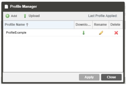
| Action | Button | Description |
| Add New Profile | Adds a new profile from current settings. User must name profile before creation is complete. | |
| Upload Profile | Allows the user to browse to external storage or workstation to upload profile to MRD. | |
| Apply Profile | Select a profile from the drop-down menu and click this button. The MRD will apply all settings contained in the profile selected. | |
| Rename Profile | Select a profile from the drop-down menu and click this button. The user will be prompted for a new name for the profile. | |
| Delete Profile | Select a profile from the drop-down menu and click this button. The user will be prompted to confirm deletion of the profile. | |
| Download Profile | Select a profile from the drop-down menu and click this button. The user will be prompted to select a directory to download the profile. |
3.3.4 Download SNMP MIB Files
The MRD 7000 stores the SNMP MIB files for the currently installed version of software on the unit. These files can be downloaded directly from the MRD 7000 by clicking on the ![]() button. This will open http://<IPAddress>/mibs. The browser screen below will appear where the files can be downloaded and saved from the unit.
button. This will open http://<IPAddress>/mibs. The browser screen below will appear where the files can be downloaded and saved from the unit.  3.3.5 Diagnostics
The MRD 7000 provides the user the ability to take a snapshot of ALL current unit settings, reported values, active alarms, and the alarm and log file history. This snapshot will be downloaded as a .XML format file that can be sent to Procare at Sencore for analysis.
Click the ‘Diagnostics’ button and a window will open showing the diagnostic file creation progress.
This window is replaced with a download file window when file creation is complete.
The user will be asked to ‘Open’ or ‘Save’ the file.
3.3.6 Security Manager
The Security Manager is used to configure certificate information for FTPS and Samba access. 
| Setting | Range | Description |
| Country Name | User entry | Country Name for generated CSR file |
| State or Province Name | User entry | State/Province Name for generated CSR file |
| Locality Name | User entry | Locality Name for generated CSR file |
| Organization Name | User entry | Organization Name for the generated CSR file |
| Organizational Unit Name | User entry | Organizational Unit Name for the generated CSR file |
| Common Name | User entry | Common Name for the generated CSR file |
| Email Address | User entry | Email Address for reference on the generated CSR file |
| Generate New CSR File | This icon will generate a new Certificate Signing Request file (CSR) using the configured IP from eth0 for the CSR file name. Additionally, the Security Manager will generate a local private key file that can be sent to a certificate agency to have a CA-signed certificate created. | |
| Certificate | Use this icon to upload the externally CA- signed certificate file. |
After uploading a Certificate to the unit, it may be removed with the red minus icon.![]() Upon removing the uploaded file, it will revert to using its own on-board self-signed certificate.
Upon removing the uploaded file, it will revert to using its own on-board self-signed certificate.
3.3.7 File Transfer Management
The File Transfer Management configuration button opens a menu in which you can enable or disable authentication for uploading pre-recorded media files. Any changes made to the File Transfer Management will affect the FTP(S) access and the PC File Manager access to the MRD 7000. 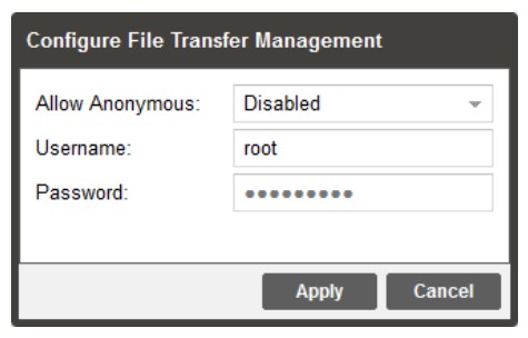
| Setting | Range | Description |
| Allow Anonymous | Enabled Disabled | Enabled allows access to media storage without a username or password. Any app capable of FTP may access the capture repository. Disabled allows access to media storage with a username and password required. Only apps capable of FTPS may access the capture repository. |
| Username | Alpha-Numeric Entry Up to 32 characters | User-defined username for access to media storage |
| Password | Alpha-Numeric Entry Up to 32 characters |
User-defined password for access to media storage |
3.3.8 Updating the MRD 7000
Updates to the MRD are performed through the web interface. A software update file is provided by Sencore and then uploaded to the unit
To request the latest software version or a copy of the release notes email ProCare@Sencore.com.
3.3.8.1 Applying Software Updates
Once the software file is downloaded the update can be performed under the Admin tab of the MRD 7000 Web-Interface. Click on the Update Unit button in the top right of the page. The current uploaded versions are displayed in the “Software Versions” section.
| Action | Button | Description |
| Upload | To upload software updates to the MRD click this button. The user will be prompted to navigate to an update file. The file will then upload to the MRD. When complete the Update Unit menu will show the Update button available. | |
| Delete | Clicking this button prompts the user to confirm the deletion of the software update from the MRD. This will also clear the Uploaded Version status of the Software Versions section. | |
| Update Software to Uploaded Version | Clicking the button starts the software update process. The MRD will prompt the user to confirm
the update. Click Yes to continue or No to cancel. |
Update Procedure:
- Click Upload button and browse to the appropriate software file
- A progress bar will show uploading status
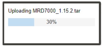
- Once the file is uploaded click on Yes when prompted to update. Doing this will prompt an automatic reboot of the system, so plan accordingly if a maintenance window is required.
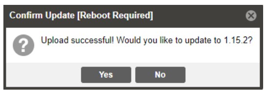
- After clicking ‘Yes’, these steps run automatically, left to right, top to bottom. Do not power cycle or otherwise interfere with the unit as it proceeds with the upgrade. The MRD will reboot after the software update is complete.

- When the upgrade is complete, the login prompt will be presented as indicated below. It is recommended to clear the browser cache between upgrades, as some front-end options are subject to change between versions.
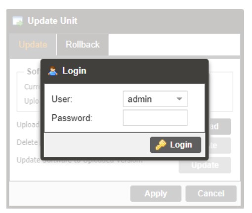
3.3.8.2 Rollback Software Updates
The MRD stores two partitions, one with the current software and settings as well as a backup image of the last software version with settings from before the upgrade. The MRD can be reverted to that backup partition using the “Rollback” feature.
To perform a rollback, click the Update Unit button and then click the Rollback tab. The MRD will reboot after the rollback process is complete. 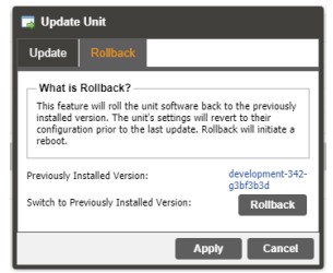
| Action | Button | Description |
| Rollback | Clicking this button starts the Rollback process. The MRD will prompt the user to confirm the rollback or click cancel to stop the process. |
3.3.9 Reboot Unit
The MRD can be rebooted from the web interface Admin page. To perform a reboot, click the reboot button. The MRD will prompt the user to confirm the reboot. Once the reboot is complete the login screen will appear allowing the web interface to be logged into. 3.3.10 Reset to Defaults
The MRD settings can be reset to factory defaults. All settings will be returned to the factory defaults except the network management ports TCP/IP settings. All event logs will be cleared. To reset all settings to default, click the Reset to Defaults button on the Admin page. The MRD will prompt the user to confirm the reset.  3.3.11 Unit Alias
The Unit Alias allows a unique name or description to be entered which shows on the web-interface title pane. This is configured inside the Admin page.  3.3.12 Decoder Settings
Decoder Settings are for options that affect the “Decoders” (Decoder 1, Decoder 2, Decoder 3, Decoder 4). Options here are for aliasing on the individual Decoders and for choosing which Baseband Output ports will carry the given decoded signal. 
| Setting | Range | Description |
| Decoder X Alias | Up to 32 Characters | Allows a user to have a desired name linked to the specified decoder tab |
| Display Alias Name Only | Checkbox | If selected, only the user entered Decoder Alias will be displayed for the Decoder tab. |
| Baseband Output Port | None ASI/SDI Module 1 Port 1-4 ASI/SDI Module 2 Port 1-4 SMPTE2110 Module 1 SMPTE2110 Module 2 |
Options available here are dependent upon Port Configuration as assigned in Section 3.3.15. After choosing an SDI Port or SMPTE2110 Module for one Decoder, it will no longer be available for selection on other Decoders. If an ASI/SDI Port is being used elsewhere as an ASI Input or Output, it will not be available for selection on this menu. If None is selected, the Decoder will enter “Gateway Mode”, where all Decode and Baseband related settings are removed and only the Data Output is used. |
After configuring the Decoder Settings, if any changes were made to Baseband Output Ports, a reboot will be required to fully apply those settings. After the reboot, the changes will become apparent under the “Baseband Output” section (see Section 3.2.6) for the modified Decoder(s).
3.3.13 Configure Unit Networks
The MRD 7000 can be assigned a Hostname and DNS servers. To access this menu, click on the Configure Networks gear icon in the Admin page.
The Default Gateway of the web-interface can also be pointed at a chosen network port (Eth0 or Eth1). The web-interface is accessible from the IP address of either Ethernet port; however, be sure to configure the two ports for separate subnets. 
| Setting | Range | Description |
| Network Name | Alphanumeric, no spaces allowed | This setting allows the user to define an optional unit Hostname. |
| Mode | Static DHCP | IP is entered by user and will not change IP is assigned to MRD by network/router |
| IP Address | Four decimal octets: XXX.XXX.XXX.XXX | This option is only available if Static Mode is set. This is the IP address assigned to the management port. |
| Subnet Mask | 255.0.0.0 – 255.255.255.254 | This option is only available if Static Mode is set. This is the Subnet Mask assigned to the management port. |
| Gateway | Four decimal octets: XXX.XXX.XXX.XXX | This option is only available if Static Mode is set. This is the Gateway address assigned to the management port. This setting will need to match your NMOS handshake port. Refer to section 3.3.14. |
3.3.14 NMOS Settings
With the SMPTE 2110 module and the MRD 70760 NMOS license, a user can configure NMOS connections. To access this menu, click on the Configure NMOS Settings gear icon under the NMOS Settings section in the Admin page.
| Setting | Range | Description |
| NMOS Feature | Enable/Disable | Enable or Disable NMOS feature. |
| Physical Connector | eth0-ethX | The physical ethernet port that NMOS will communicate through. NMOS communication occurs only on the interface chosen as the Default Gateway, under “Unit Network settings”. See Section 3.3.12. |
| Port | 1-65535 | The port that NMOS will make the initial connection handshake on. Ports 21, 22, 80, 445, and 5353 are not supported as they are reserved ports. |
| Registration Mode | Service Discovery Manual | Service Discovery obtains an NMOS RDS IP address from a DNS. Manual bypasses a DNS and connects directly to an NMOS RDS. |
| Manual Address | Four decimal octets: XXX.XXX.XXX.XXX | The hostname or IP address of an NMOS RDS |
| Manual Port | 1-65535 | The port number the NMOS RDS is listening on |
| Unicast DNS | Enabled Disabled | Enable or Disable whether to connect to an NMOS RDS using Unicast DNS |
| Unicast Domain | The domain of the NMOS DNS. Leave blank for the system to attempt the connection as default. | |
| Multicast DNS | Enabled Disabled | Enable or Disable whether to connect to an NMOS RDS using Multicast DNS |
3.3.15 Configure SMPTE 2110 Video/IP Networks
With the SMPTE 2110 module, a user can configure the Video/IP Redundancy Mode. To access this menu, click on the Configure gear icon under the Video/IP Network Module 1 section in the Admin page.
The PTP Master Domain can also be adjusted to synchronize the grand master PTP clock. Module Adapter
| Setting | Range | Description |
| IP Address | Four decimal octets: XXX.XXX.XXX.XXX |
This is the IP address assigned to the SFP port on the selected SMPTE 2110 port. |
| Subnet Mask | 255.0.0.0 – 255.255.255.254 | This is the Subnet Mask assigned to the SFP port on the selected SMPTE 2110 port. |
| Gateway | Four decimal octets: XXX.XXX.XXX.XXX | This is the Gateway address assigned to the SFP port on the selected SMPTE 2110 port. |
Video/IP Module
| Setting | Range | Description |
| Redundancy Mode | Seamless Disabled | When seamless is selected, the MRD 7000 will operate within the SMPTE 2110 standard mode. This mode will provide primary and redundant paths for configuration in the separate stream processing paths. When disabled the MRD 7000 will provide a single IP path for input and output streams and the user will determine the appropriate |
| PTP Master Domain | 0-127 | The Domain identified used to sync to the PTP source. |
| Output Mode | 1x UHD/HD/SD 4x HD/SD | This option changes the Decoder Output Modes. See |
| Reference Format | See Genlock supported formats in Appendix C | The Reference Format must be set to match the decoded Video Format. This can also be used to sync your video output to a Genlock reference device. |
3.3.16 Configuring ASI/SDI Ports
These menus are used to orient the decode mode of the unit and allocate purpose to each of the BNC connectors on the MRD 70140 and MRD 70141 cards. Setting changes made here will potentially affect options available on the Decoder Settings (Section 3.3.11) and Data Outputs (Section 3.2.7). A reboot must be applied for the changes to take effect. Review the possible Decoder and Output Mode combinations in Section 3.3.18.
3.3.17 Configuring Genlock
SDI Output modules with the “Reference Source” configured as External must manually define the Genlock Format for the card to lock to the Genlock signal. SDI over IP (2110) modules require the “Reference Format” to always be configured to properly output video. In Multichannel decode applications, the same Genlock reference is used for all SDI outputs.
3.3.17.1 Genlock SDI Output Module
SDI Output Module Genlock settings can be activated in the Admin panel under the ASI/SDI module. 3.3.17.2 Genlock 2110 Output Module
SDI over IP (2110) Output Module Genlock settings can be activated in the Admin panel under the Video/IP module.  3.3.18 Configuring Satellite Ports
To make changes to lock onto the satellite signal click on the configure button next to the Satellite Module.  The Satellite Module can be configured within the port menu. This allows the user to lock onto the input signal by changing the port, mode, modulation, frequency, offset, symbol rate, and scrambling code. The module can supply LNB power and provide multi-stream.
| Setting | Range | Description |
| Port | Enabled Disabled |
Enable/Disable the Satellite Input |
| Mode | DVB-S DVB-S2/DVB-S2X |
Select which modulation mode to receive for the Satellite input |
| Modulation | QPSK 8PSK/8APSK-L 16APSK/16APSK-L 32APSK/32APSK-L 64APSK/64APSK-L 128APSK 256APSK/256ASPK-L |
Select the modulation type |
| Satellite Frequency | 950 – 14500 | The carrier frequency in MHz of the input signal |
| LO Offset | 0 5150 9750 10600 |
Choose or enter the frequency offset in MHz based on the current input signal and the above Satellite Frequency value |
| 10750 11250 |
||
| Symbol Rate | 0.5 – 60 | The symbol rate in MSps of the modulated input signal |
| PL Scrambling Code | 0 – 262141 | The PL Scrambling code value of the modulated signal |
| LNB Power | Off 13 VDC 18 VDC |
Chose to enable LNB Power and specify the output voltage that match the application |
| 22kHz Tone | Enabled Disabled |
Enable/Disable the 22kHz tone based on LNB Power configuration |
| Multi-stream State | Enabled Disabled |
Enable/Disable the Multi-stream state based on your current DVB-S2 input signal |
| ISI | 0 – 255 | The unique ID of the input signal within the DVB-S2 multi-stream input signal |
3.3.19 Configuring Decoder Output Modes
MRD 7000 allows a user to decode single UHD or Multichannel HD/SD outputs. The two output types are SDI or SDI over IP (SMPTE 2110). The mode of operation for the MRD 7000 will depend on the licensing and output card installed.
Multichannel mode (4 Independent HD/SD channels) is configurable when unit is equipped with the MRD 70120, MRD 70140, MRD 70141, MRD 70180 or MRD 70182 module. Single Port/Link UHD for MRD 70141, MRD 70180 or MRD 70182. Quad Link UHD for MRD 70140 or MRD 70141.
3.3.19.1 Configuring SDI Single Port UHD Decoder Outputs
To change from Quad Link UHD or Multichannel mode to Single Port UHD mode, the user needs to select 12G-SDI + ASI (UHD) from the Module Configuration list. After reboot, confirm Port 1 is set to SDI and Port 2 is set to ASI. Ports 3 and 4 should be disabled.  When unit completes boot up, clear the browser cache by pressing Ctrl+Shift+R to remove any front-end memory of the previous config. Verify the configuration now matches the image below. Port 1 are set to SDI, while Port 2 is set to ASI. Ports 3 and 4 will be disabled.
 When 12G-SDI + ASI (UHD) mode is successfully applied, the user can then configure a Single Port UHD decoder via Decoder 1 as shown below.
  3.3.19.2 Configuring SDI Multichannel Decoder Outputs
To change from Quad Link UHD or Single Port UHD mode to Multichannel mode, the user needs to select Independent (HD/SD) from the Module Configuration list. After reboot, confirm Ports 1 through 4 are set to SDI.  When unit completes boot up, clear the browser cache by pressing Ctrl+Shift+R to remove any front-end memory of the previous config. Verify the configuration now matches the image below. All ports are set to SDI, and cogs to configure each of them are now available.
 When Independent (HD/SD) mode is successfully applied, Multichannel decoding is available via Decoder 1, Decoder 2, Decoder 3, and Decoder 4 tabs. The Summary tab displays overall status for all decoders.
  3.3.19.3 Configuring SDI Quad Link UHD Decode Outputs
To change from Multichannel mode or Single Port UHD mode to Quad Link UHD mode, select Quad 3G-SDI (UHD) from the Module Configuration list. After reboot, confirm Ports 1 through 4 are set to SDI and no configuration cog is available. Also confirm only 1 decoder tab is available in the Web GUI.  When unit completes boot up, clear the browser cache by pressing Ctrl+Shift+R to remove any front-end memory of the previous config. Verify the configuration now matches the image below. All ports are set to SDI, and no configuration cogs present.
  When Quad 3G-SDI (UHD) mode is successfully applied, the Quad Link UHD decode will now be available via Decoder 1.
  3.3.19.4 Configuring 2110 Single Link UHD Decode Outputs
To change from Multichannel Mode to Single Link UHD mode, select 1x UHD/HD/SD from the Output Mode list. Click ‘Apply’ and then ‘Yes’ to commit the setting and reboot.  When unit completes boot up, clear the browser cache by pressing Ctrl+Shift+R to remove any front-end memory of the previous config. Verify there is now only one Decoder tab as shown in the image below. In 1x UHD/HD/SD mode, the user can configure a Single Link UHD decoder via Decoder 1.
 3.3.19.5 Configuring 2110 Multichannel Decoder Outputs
To change from Single Link UHD mode to Multichannel mode, the user needs to select 4 HD/SD from the Output Mode list. After reboot, confirm Decoders 1 through 4 are available.  When unit completes boot up, clear the browser cache by pressing Ctrl+Shift+R to remove any front-end memory of the previous config. Verify there are now four Decoder tabs as shown in the image below.
  When 4x HD/SD mode is successfully applied, the user can then configure Multichannel decoding available via Decoder 1, Decoder 2, Decoder 3, Decoder 4 tabs. Summary tab displays overall status for all decoders.
3.3.20 Licensing
Certain features of the MRD require licenses to be functional. The interface displays all licenses available as well as the following status:
- License Locked or Unlocked
- License is Supported or Unsupported by the installed hardware
If licenses need to be applied to the MRD click Apply License Key button. The menu below will appear where the user can copy and paste the provided license key from Sencore.  3.3.20.1 Software Support Agreements
Purchase of the MRD 7000 software includes one year of software support. This provides access to the latest software versions throughout that one-year period. These software versions include:
- Bug fixes
- General updates
- Maintenance releases
The MRD 7000 will only accept software files which were released before or during the active SSA period. Software updates released following the expiration of the SSA will be rejected on upload, until the product’s SSA has been re-activated. The actual SSA information is maintained on the product itself and can be updated by applying a license key via the web user interface. The product’s user interface displays the end date to ensure the user is always informed of their SSA status. Regardless of the status of the software subscription agreement, Sencore offers phone and email technical support during regular business hours for all products.
Once the SSA period has expired, customers are free to keep using the software version hey already have or other versions from before the expiration date but applying newer versions will require an extended SSA.  3.3.21 Date/Time
The MRD can be set to synchronize with an NTP server, or a manual data and time can be defined by the user. Click the Configure Date / Time button to configure the date and time. These values are used to timestamp entries in the Alarm and Event logs under the Reporting tab. 
| Setting | Range | Description |
| Update Mode | NTP Manual |
Setting to NTP uses the local network’s NTP server to synchronize date and time. Manual allows the user to define a date and time. |
| NTP Server | Four decimal octets: XXX.XXX.XXX.XXX Domain Name |
This is the IP Address or Domain Name of the local NTP Server on the network. This setting is only available if Update Mode is set to NTP. |
| Date | MM/DD/YYYY | This setting is the user defined date. A calendar widget can be used to select the data by clicking the button. This setting is only available if Update Mode is set to Manual. |
| Time | 00:00:00 – 24:00:00 | This setting is the user defined time. The time is based on a 24-hour clock. This setting is only available if the Update Mode is set to Manual. |
3.3.22 SNMP Communities
Click on the SNMP Community configuration under the Admin tab for manual entry of the read and write communities. 3.3.23 SNMP Trap Managers
Click on the SNMP Trap Manager configuration icon to adjust the IP address of the SNMP trap destination. An example is provided below.  3.3.24 Syslog
The MRD 7000 can be configured to send error and event logs formatted in the syslog protocol to a remote user specified Syslog server. 
| Action | Range | Description |
| State | Enabled Disabled |
Enable or Disable sending messages to Syslog server. |
| Network Protocol | UDP TCP |
Select which network protocol used to transmit to the Syslog server |
| IP Address | Four decimal octets: XXX.XXX.XXX.XXX |
IP of the Syslog server. 0.0.0.0 and 255.255.255.255 are not permitted |
| Port | 0 – 65535 | Destination port of the Syslog server |
3.4 Reporting Panel
The Reporting tab in the MRD 7000 contains logs for active alarms currently affecting the unit and an event log. The active alarms are updated periodically to reflect the realtime state of the unit.
Once an error is cleared it will be cleared from the active alarms window.
The event log can be used to view alarm and event history. Both the active alarm and event logs can be configured to hide or change the behavior of alarms and events.
3.4.1 Active Alarms
Clicking on the Alarms button displays the Active Alarms menu. This list displays all the active alarms currently affecting the unit. There are four columns in the log that display different types of information.
| Title | Description |
| State | This column displays the nature of the alarm. The |
| Name | This column displays the description of the error. The function that is experiencing an error condition is described here. |
| Location | This column displays the hardware or function that is experiencing the active error. |
| Last Changed | This column displays the data and time the error was raised. This date and time correlates to the Date and Time settings configured in Section 3.3.20. |
3.4.2 Event Logs
Clicking on the Logs button displays all the events and alarms that have affected the unit. If the unit is rebooted or powered off/on, the event logs are cleared. The logs can also be cleared manually by clicking the Clear button. The logs can be downloaded as a “.csv” file and saved to an external location by clicking the Download button.
| Title | Description |
| Severity | This column displays the nature of the alarm. The |
| Timestamp | This column displays the data and time the error was raised or cleared. This date and time correlates to the Date and Time settings configured in Section 3.3.20. |
| Transition | This column displays when an alarm transition from a bad to good state. When an error is raised the |
| Message | This column displays the description of the error or event. The function or hardware that experienced the event or error is described here. |
| Location | This column displays the hardware or function that experienced the alarm or event. |
3.4.3 Configuring the Logs
The MRD 7000 allows the user to configure alarms and events. Events and alarms can be Logged, Hidden, or have the Severity adjusted. To configure these options, click the Configure button while in the Reporting tab. When multi-channel decoder option is enabled, the logs and events are configured separately for each individual decoder.
 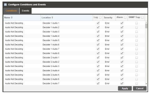 Each column and its function are described below. A user configured time offset can also be applied to allow viewing the logs in a local time zone.
| Title | Description |
| Name | This column displays the name of the error or condition. This is informational data: no options can be set here. |
| Location | This column displays the hardware or function that the alarm or event applies to. This is informational data; no options can be set here. |
| Log | Checking the box in this column creates an entry in the event log in the case this error or event is raised. If this box is unchecked this error or event will be hidden and not logged if raised. |
| Log Severity | This column is only available in the |
| Alarm | This column is only available in the |
3.5 About Panel
Under the About tab, there are no user definable parameters but there is information about software versions currently installed, which licenses are installed, how to contact Sencore, and third-party software information.
Section 4 Appendices
 Introduction
This section includes the following appendices:
Appendix A – Acronyms and Glossary
AAC: Advanced Audio Coding
AC-3: Also known as Dolby Digital
AES: Audio Engineering Society
ATSC: Advanced Television Systems Committee
BISS: Basic Interoperable Scrambling System
Bit Rate: The rate at which the compressed bit stream is delivered from the channel to the input of a decoder.
BNC: British Naval Connector
dB: Decibel
DHCP: Dynamic Host Configuration Protocol
DVB: Digital Video Broadcasting
Event: An event is defined as a collection of elementary streams with a common time base, an associated start time, and an associated end time.
FCC: Federal Communications Commission
HD: High Definition
I/O: Input/Output
IP: Internet Protocol
Kbps: 1000 bit per second
LED: Light Emitting Diode
Mbps: 1,000,000 bits per second.
MPEG: Refers to standards developed by the ISO/IEC JTC1/SC29 WG11, Moving
Picture Experts Group. MPEG may also refer to the Group.
MPEG-2: Refers to ISO/IEC standards 13818-1 (Systems), 13818-2 (Video), 13818-3 (Audio), 13818-4
NMOS: Networked Media Open Specifications
NTP: Networking Time Protocol
PCM: Pulse-Code Modulation
PID: Packet Identifier. A unique integer value used to associate elementary streams of a program in a single or multi-program transport stream.
Program specific information (PSI): PSI consists of normative data which is necessary for the demultiplexing of transport streams and the successful regeneration of programs.
Program: A program is a collection of program elements. Program elements may be elementary streams. Program elements need not have any defined time base; those that do have a common time base and are intended for synchronized presentation.
RDS: Registration and Discovery Server
RU: Rack Unit
SD: Standard Definition
SDI: Serial Digital Interface
SI: System Information
SMPTE: Society of Motion Pictures and Television Engineers
SNMP: Simple Network Management Protocol
SRT: Secure Reliable Transport
TS: Transport Stream
Appendix B – Error and Event List
| Error | Description |
| Audio Not Decoding | Indicates selected service is not decoding an audio PID. |
| Auto Video Format Error | The MRD encountered an error when automatically choosing the output format. |
| Closed Caption Line Conflict | The VANC line Closed Captions are currently set to be embedded on are conflicting with another line of data in the VANC. |
| Date/Time Changed | The Date/Time setting of the system was changed. |
| Decoder Latency Too Low | The parallel frames processing setting is too low for the decoded video codec. Recommended action is to set parallel frame processing to default or increase the number of frames. |
| Firmware Unsupported | The uploaded software is not supported by the MRD 7000. |
| HLS Link Connection Error | The system encountered a connection error when receiving an HLS transmission. |
| HLS Link Loss Error | HLS stream sync is not detected. |
| Incompatible Reference Format | The system has detected that the genlock frame rate does not match the video output frame rate |
| Input Video Unsupported | The video source format or codec is unsupported. |
| Insufficient Decoder Performance | The unit does not have enough processing power to decode the transport stream. Contact ProCare@sencore.com for support. |
| IP Link Loss Error | MPEG/IP or Seamless RTP stream sync is not detected. |
| Loss of Carrier Lock | Receiver carrier lock source is lost. |
| Network Interface Link Down | Triggers an alarm if the physical interface is not detected as active |
| NMOS Registration Server Not Found | Unable to connect to the NMOS RDS the unit is configured to contact. |
| No Services Detected | There are no service detected on the active input. |
| NTP Server Unreachable | The NTP serve was unable to be reached. |
| NTP Updated | The NTP Date/Time was updated. |
| OP47 Line Conflict | The VANC line OP47 is currently set to be embedded on is conflicting with another line of data in the VANC. |
| Private Key file Not Valid | The uploaded file does not match the necessary Private Key file to descramble the stream content. |
| Reboot Required for HTTPS Certificate To Be Removed | An External Security certificate that was added (per Section 3.3.6) has since been removed, and a reboot is required to revert to using Self-Signed Certificates for FTPS/Samba. |
| RTMP Link Connection Error | The system encountered a connection error when receiving an RTMP transmission. |
| RTMP Link Loss Error | RTMP stream sync is not detected. |
| RTP Reception Error | RTP IP statistics has detected an out of order, duplicate, or lost packet or discontinuity in the incoming MPEG/IP or Seamless RTP stream. |
| SCTE 104 Line Conflict | The VANC line SCTE 104 is currently set to be embedded on is conflicting with another line of data in the VANC. |
| SCTE 104 Message Embedded | The SCTE 104 message was successfully embedded into the stream. |
| SCTE 35 Message Received | The SCTE 35 message was received on the input |
| SCTE35 Heartbeat Timeout | The user settable time limit has been exceeded between SCTE35 messages. |
| Service Not Found | No services were found on the configured input. |
| SMPTE2031 Line Conflict | The VANC line SMPTE2031 is currently set to be embedded on is conflicting with another line of data in the VANC. |
| SMPTE2038 Line Conflict | The VANC line SMPTE2038 is currently set to be embedded on is conflicting with another line of data in the VANC. |
| SMPTE2108 Line Conflict | The VANC line SMPTE2108 is currently set to be embedded on is conflicting with another line of data in the VANC. |
| Software Update Failed | An attempted software update was unsuccessful. |
| Software Update Succeeded | An attempted software update succeeded. |
| SRT Receive Connection Error | The system encountered a connection error when receiving SRT transmission. |
| SRT Receive Decryption Wrong Passphrase | The system has errors when trying to decrypt a SRT signal with the incorrect passphrase. |
| SRT Receive Lost Packets Error | The system has detected lost packets in the received SRT signal. |
| SRT NAK Transmit Error | The system has sent a NAK resend request back to the transmitter |
| SRT Receive Uncorrected Packets Error | The system has requested a retransmission of packets which were not received |
| Stream Not Present | The decoder is not receiving a transport stream from the configured input. |
| TS Sync Loss Error | Active input transport stream lost sync. (ETR Priority 1 Error) |
| Unicast Receiver Not Found | There is no connection between Unicast Transmitter and Receiver on the configured Destination Address and Port |
| Unit Booted | The system completed a boot process. |
| Video Not Decoding | The video payload in the selected service cannot decode. |
| Vpid Line Conflict | The VANC line Vpid is currently set to be embedded on is conflicting with another line of data in the VANC. |
| Zixi Receive Connection Error | The system encountered a connection error when receiving Zixi transmission. |
| Zixi Receive Decryption Error | The system has errors when trying to decrypt Zixi signal |
| Zixi Receive Dropped Packets Error | The system has detected dropped packets in the received Zixi signal |
| Zixi Receive Not Recovered Packets Error | The system is reporting that retransmitted packets were not recovered in the received Zixi signal |
Appendix C – Specifications
MRD 7000 Minimum Requirements
| For H.264 1080P60 Decode | |
| CPU: RAM: HDD: |
Intel Xeon D-1520, 2.2GHz 16GB DDR4 2133MHz 256GB SSD |
| For HEVC 4K UHD 60MB Decode | |
| CPU: RAM: HDD: |
Intel Xeon E-2176G, 6-core, 3.7Ghz 32GB DDR4 2666MHz 256GB SSD |
| For HEVC 4K UHD 160MB Decode | |
| CPU: RAM: HDD: |
Intel Gold 6212U, 24-core, 2.4GHz 64GB DDR4 2933MHz 256GB SSD |
Base Video Decoding Features
| General – | |
| TS Data Rate: | .25-200 Mb/s |
| Video Decoder – | |
| Video Profiles and Levels: | Base Software – Up to MPEG-2 422P@HL (HD Formats) Up to H.264 Hi422P@4.2 (HD Formats) Up to HEVC Main 4:2:2 10 (HD Formats) Up to JPEG2000 (HD Formats) |
| Video Bit Rate: | MRD 70081: MPEG-2 1-160Mb/s H.264 1-160Mb/s HEVC 1-160Mbps MRD 70080: MPEG-2 1-100Mb/s |
| H.264 1-100Mb/s HEVC 1-160Mbps MRD 70050 MPEG-2 1-100Mb/s H.264 1-100Mb/s HEVC 1-50Mbps MRD 70020 MPEG-2 1-100Mb/s H.264 1-100Mb/s HEVC 1-70Mbps |
|
| Video Formats: | Base Software – 1080p x 1920 (16×9) @ 50, 59.94 and 60Hz 1080i x 1920 (16×9) @ 25, 29.97 and 30Hz 1080p x 1920 (16×9) @ 23.97, 24, 25, 29.97 and 30Hz 720p x 1280 (16×9) @ 50, 59.94, and 60Hz 576i x 720 (4×3 or 16×9) @ 25Hz 576i x 704 (4×3 or 16×9) @ 25hz 576i x 544 (4×3 or 16×9) @ 25hz 480i x 720 (4×3 or 16×9) @ 29.97Hz SD-SDI – 270Mb/s MRD 70706 License Adds – 2160p x 3840 (16×9) @ 23.97, 24, 25, 29.97, 30, 50, 59.94, and 60Hz NOTE: This license adds UHD resolutions and 4x channel decoding. Some MRD 7000 output modules do not support UHD output but do support 4x HD/SD channel output. |
| HDR Formats: | HDR10 (SMPTE 2084 & SMPTE 2086) HLG (ARIB STD B67) |
| Base Audio Decoding Features | |
| Number of Audio Services: | 8 Audio Services per video |
| Audio Codecs Supported: | Dolby Digital (AC-3) & Plus (EAC-3) Dolby AC-4 Dolby ATMOS and Dolby E AAC-LC, HE-AAC, & HE-AACv2 MPEG1L2 & MPEG2L2 SMPTE 302M Linear PCM (Pass-through) |
| Output Formats: | Digital Pass-through PCM (Decoded Discrete channels for 5.1 Sources or Downmixed for 5.1 Sources) |
| Video Overlay Support | |
| Closed Caption Overlays: | CEA-708 |
| DVB Subtitle & Teletext Overlays: | HD/SD with Auto Scaling (EN 300743) |
| Conditional Access | |
| Descrambling Options: | BISS1 BISS2 |
| Compatibility Standard: | DVB-CSA1 DVB-CISSA AES-128 RSA-2048 |
| Supported Modes: | |
| BISS1: | Mode 0 Mode 1 with Session Word Mode E with Session Word and Injected ID |
| BISS2: | Mode 0 Mode 1 with Session Word |
| Mode E with Session Word and Injected ID Mode CA with Public Key and Injected Private Key Mode CA with Public Key and Buried Private Key |
|
| Maximum TS bitrate: | 200 Mb/s |
| Number of Stored Keys: | Up to 12 Keys |
| Number of Descrambled Services: | No limitation to the number of services descrambled per key |
| MRD 7000 Input Features | |
| IP Input (included with MRD 7000) | |
| General – | |
| Connector: | 2x 100M/1000M auto negotiate Base-T RJ-45 for MRD 70020, 70050, 70080 2x 1000M auto negotiate Base-T RJ-45 for MRD 70081 (100M auto negotiate support with MRD 70200 installed) Ethernet Ports |
| Receive – | |
| Input Format: | UDP, RTP and RTP with extension headers Multicast and Unicast CBR, VBR SMPTE 2022-7 Hitless switching |
| Multicast Filtering: | Filters based on IP address |
| Bitrate Range: | .25 – 200 Mb/s |
| Packets/IP Frame: | 1-7 MPEG Packets/IP Frame |
| IGMP Compatibility: | Version 2 and 3 |
| FEC Receive: | Pro MPEG CoP3 SMPTE2022 Range: L*D≤100 1≤L≤20 4≤D≤20 Annex B |
| MRD 70750 – SRT Input License | |
| General – | |
| Connector: | 2x 100M/1000M auto negotiate Base-T RJ-45 for MRD 70020, 70050, 70080 2x 1000M auto negotiate Base-T RJ-45 for MRD 70081 (100M auto negotiate support with MRD 70200 installed) |
| Receive – | |
| Protocol and IP Range: | UDP, Unicast |
| Negotiation Modes: | Caller, Listener, Rendezvous |
| Latency: | 20-8000ms, user configurable |
| Bitrate Range: | .25 – 50 Mb/s |
| Decryption: | AES-128, AES-256
10-79 UTF-8 characters |
| Packets/IP Frame: | Auto detect |
| MRD 70751 – Zixi Input License | |
| General – | |
| Connector: | 2x 100M/1000M auto negotiate Base-T RJ-45 for MRD 70020, 70050, 70080 2x 1000M auto negotiate Base-T RJ-45 for MRD 70081 (100M auto negotiate support with MRD 70200 installed) |
| Receive – | |
| Protocol and IP Range: | UDP, Unicast |
| Mode: | Connect (Pull) Mode |
| Latency: | 30-10000ms, user configurable |
| Bitrate Range: | 1 – 50 Mb/s |
| FEC Overhead: | 0-50% of content bitrate |
| Decryption: | AES-128, AES-192, AES-256
10-79 UTF-8 characters |
| Packets/IP Frame: | Auto detect |
| MRD 70753 – RTMP Input License | |
| General – | |
| Connector: | 2x 100M/1000M auto negotiate Base-T RJ-45 for MRD 70020, 70050, 70080 2x 1000M auto negotiate Base-T RJ-45 for MRD 70081 (100M auto negotiate support with MRD 70200 installed) |
| Receive – | |
| Protocol and IP Range: | TCP, Unicast |
| Payload: | MP4, FLV containing H.264 and AAC or MP3 Audio |
| Mode: | Pull |
| Bitrate Range: | 0.25 – 50 Mb/s |
| MRD 70754 – HLS Input License | |
| General – | |
| Connector: | 2x 100M/1000M auto negotiate Base-T RJ-45 for MRD 70020, 70050, 70080 2x 1000M auto negotiate Base-T RJ-45 for MRD 70081 (100M auto negotiate support with MRD 70200 installed) |
| Receive – | |
| Protocol and IP Range: | HTTP, HTTPS, TCP, Unicast |
| Payload: | Chunked transport stream |
| Mode: | Pull Profile Reception Single profile selection |
| Bitrate Range: | 0.25 – 50 Mb/s |
| FEC Overhead: | 0-50% of content bitrate |
| Decryption: | AES-128 |
| Packets/IP Frame: | 1-7 MPEG Packets/IP Frame |
MRD 70170 – 4x ASI Input Module (1 slot)
| General – | |
| Connector: | 4x BNC, Female |
| Impedance: | 75Ω |
| Return Loss: | ≥15dB, 3.5 to 270 MHz |
| ASI Input – | |
| Standard: | EN50083-9 (V2:3/98) DVB ASI |
| Data Bit Rate: | 214 Mb/s per port |
| Maximum TS Rate: | 200 Mb/s per port |
| Minimum TS Rate: | 250 Kb/s per port |
| Packet Sizes | 188 bytes |
| Modes Supported: | Burst, Byte and Inverted |
| MRD 70191 – 4x DVB-S/S2 Satellite Input Module (1 slot) | |
| DVB-S/S2X tuner | 4 satellite-inputs Up to 8 multi-standard demodulators F-81 Type, 75 Ohms Female (4) connectors Short Frames ACM (Adaptive Coding and Modulation) VCM (Variable Coding and Modulation) MIS (Multiple Input Streams) |
| Satellite characteristics – | |
| Modulation: | QPSK |
| 8PSK/8APSK-L | |
| 16APSK/16APSK-L | |
| 32APSK/32APSK-L 64APSK/64APSK-L 128APSK 256APSK/256APSK-L |
|
|
Specifications: |
LNB Power: 4 * max. 19V, 1A pulse current, 500mA continuous current overcurrent protection short-circuit protection |
| L-Band: 950 MHz to 2150 MHz | |
| DVB FEC: (Auto Spectral Detection) 188-byte packet size | |
| Symbol rates – | |
| QPSK: | 95 MSym |
| 8PSK/8APSK: | 86 MSym |
| 16APSK: | 64.5 MSym |
| 32APSK: | 51.6 MSym |
| 64APSK: | 43 Msym |
| 128APSK: | 36.85 Msym |
| 256APSK: | 32.25 Msym |
| Sensitivity (@25MSym) – | |
| QPSK 11/45: | -89 dBm (20 dBµV) |
| QPSK 1/2: | -86 dBm (23 dBµV) |
| 8PSK 9/10: | -77 dBm (32 dBµV) |
| 256APSK 3/4: | -69 dBm (40 dBµV) |
| Additional features – | |
| Strong signal immunity: | > 106dbµV (-6dBm) |
| Isolation: | 65dB – 80dB depending on signal strength |
MRD 7000 Output Features
MRD 70130 – 12G-SDI and HDMI 2.0b Output Module, Genlock (1 slot)
| Ports: | 1x 1xASI in 1x 12G-SDI out 1x HDMI 2.0 out 1x Genlock in |
| Connectors: | 3x 75-Ω BNC 1x HDMI type A receptacle |
| Video Standards: | SD-SDI – SMPTE 259M HD-SDI – SMPTE 292M 3G-SDI – SMPTE 424M 12G-SDI – SMPTE 2082 HDMI 2.0B |
| Video Formats: | 480i, 525i, 576i, 625i, 720p, 1080i, 1080p, 1080psf, 2160p. All common formats supported. |
| Audio Output: | Up to 8 pairs of audio streams |
| ANC Data Support: | 708 Closed Captions SMPTE 2038 SCTE 104 OP47 SMPTE 2031 VPID SMPTE 2108 |
| Genlock Interface – | |
| Genlock Connector: | 75Ω Female BNC |
| Input Impedance: | 10kΩ |
| Return Loss: | ≥20 dB, 0Mhz to 8 MHz |
| Drive Level: | 1.0 Vpp ±10% |
| Supported Genlock References: | Tri-sync and Black Burst 1080i x 1920 @ 25, 29.97 and 30fps 1080p x 1920 @ 23.97, 24, 25, 29.97, 30, 50, 59.94 and 60fps 720p x 1280 @ 50, 59.94 and 60fps |
MRD 70140 – Quad 3G-SDI Output Module, Genlock (1 slot)
| Ports: | 4x 3G-SDI out / ASI in / ASI out 1x genlock in |
|
Connectors: |
5x 75-Ω DIN 1.0/2.3 Shipped with 5x converter cable 1.0/2.3 to BNC |
| Video Standards: | SD-SDI – SMPTE 259M HD-SDI – SMPTE 292M 3G-SDI – SMPTE 424M |
| 4K multi-link | SMPTE 425-5 4 quadrant and two sample interleave Level A/B |
| Video Formats: | 480i, 576i, 525i, 625i, 720p, 1080i, 1080p, 1080psf, 2160p. All common formats supported. |
| Audio Output: | Up to 8 pairs of audio streams |
| ANC Data Support: | 708 Closed Captions SMPTE 2038 SCTE 104 OP47 SMPTE 2031 VPID SMPTE 2108 |
| Genlock Interface – | |
| Genlock Connector: | 75-Ω DIN 1.0/2.3 |
| Input Impedance: | 10kΩ |
| Return Loss: | ≥20 dB, 0 MHz to 8 MHz |
| Drive Level: | 1.0 Vpp ±10% |
| Supported Genlock References: | Tri-sync and Black Burst 1080i x 1920 @ 25, 29.97 and 30fps 1080p x 1920 @ 23.97, 24, 25, 29.97, 30, 50, 59.94 and 60fps 720p x 1280 @ 50, 59.94 and 60fps |
MRD 70141 – Quad 3G-SDI Output Module, Genlock (1 slot)
| Modes: | 1x 12G-SDI output with genlock, 1x ASI input/output 4x 3G-SDI output with genlock 4x independent 3G-SDI or ASI ports (input or output |
| Connectors: | 5x 75-Ω HD-BNC Shipped with 5x converter cable HD-BNC to BNC |
| Video Standards: | SD-SDI – SMPTE 259M HD-SDI – SMPTE 292M 3G-SDI – SMPTE 424M |
| 12G-SDI – SMPTE 2082 | |
| 4K multi-link | SMPTE 425-5 two sample interleave or square division Level A/B |
| Video Formats: | 480i, 576i, 525i, 625i, 720p, 1080i, 1080p, 1080psf, 2160p. All common formats supported. |
| Audio Output: | Up to 8 pairs of audio streams |
| ANC Data Support: | 708 Closed Captions SMPTE 2038 SCTE 104 OP47 SMPTE 2031 VPID SMPTE 2108 |
| Genlock Interface – | |
| Genlock Connector: | 75-Ω HD-BNC |
| Input Impedance: | 10kΩ |
| Return Loss: | ≥20 dB, 0Mhz to 8 MHz |
| Drive Level: | 1.0 Vpp ±10% |
| Supported Genlock References: | Tri-sync and Black Burst 1080i x 1920 @ 25, 29.97 and 30fps 1080p x 1920 @ 23.97, 24, 25, 29.97, 30, 50, 59.94 and 60fps 720p x 1280 @ 50, 59.94 and 60fps |
MRD 70150 – Basic 12G-SDI and HDMI 2.0a Output Module, Genlock (2 slots)
| x1 SDI (Serial Digital Interface) Video Output – | |
| SDI Standards: | HD-SDI ANSI/SMPTE ST 292M Single 3G-SDI ANSI/SMPTE ST 424M Quad 3G-SDI ANSI/SMPTE ST 425-5 (Quadrant) 6G-SDI ANSI/SMPTE ST 2081 |
| 12G-SDI ANSI/SMPTE ST 2082 | |
| SDI Level: | Level A or Level B (user selectable) |
| Connector: | 75Ω Female BNC |
| Return Loss: | ≥15 dB, 5Mhz to 1.5GHz ≥10 dB, 1.5 GHz to 3.0GHz |
| Drive Level: | 800 mVpp ±10% |
| Data Bit Rate: | 12G-SDI – 12 Gb/s 6G-SDI – 6 Gb/s 3G-SDI – 3.0 Gb/s HD-SDI – 1.5 Gb/s |
| HDMI 2.0 Output – | |
| Digital Video Standard: | SDA-HDMI-OM-E Rev A |
| Connector: | HDMI-type Female Type-A |
| Genlock Interface – | |
| Genlock Connector: | Requires breakout cable, Pin 6 75Ω Female BNC |
| Input Impedance: | 10kΩ |
| Return Loss: | ≥20 dB, 0Mhz to 8 MHz |
| Drive Level: | 1.0 Vpp ±10% |
| Supported Genlock References: | Tri-sync and Black Burst 1080i x 1920 @ 25, 29.97 and 30fps 1080p x 1920 @ 23.97, 24, 25, 29.97, 30, 50, 59.94 and 60fps 720p x 1280 @ 50, 59.94 and 60fps |
MRD 70120 – SMPTE 2110 Output Module, HD, 2x 10GB SFP (1 slot)
| Connectors: | 2x 10GB SFP+ (MSA Compliant) |
|
IP Encapsulation: |
SMPTE 2110-10 SMPTE 2110-20 SMPTE 2110-30 |
| SMPTE 2110-40 | |
| Packet Pacing: | SMPTE 2110-21 Type N (Narrow) |
| PTP Synchronization: | SMPTE 2059-2 |
| Output Redundancy | SMPTE 2022-7 Hitless Switching |
| Video Standards: | 8-bit and 10-bit YUV 4:2:2 SMPTE 292M, and SMPTE 425-AB |
| Video Formats: | 1080p x 1920 (16×9) @ 50, 59.94 and 60Hz NOTE: In multi-channel decoder applications, outputting more than 3x FHD streams on a 10GB link will exceed bandwidth. 1080i x 1920 (16×9) @ 25, 29.97 and 30Hz 1080p x 1920 (16×9) @ 23.97, 24, 25, 29.97 and 30Hz 720p x 1280 (16×9) @ 50, 59.94, and 60Hz |
| Audio Output: | Up to 8 pairs (16 channels) |
| ANC Data Support: | 708 Closed Captions SMPTE 2038 SCTE 104 OP47 SMPTE 2031 |
MRD 70180 / MRD 70182 – SMPTE 2110 Output Module, UHD/HD, 2x 25GB SFP (1 slot)
| Connectors: | 2x 25GB SFP28 (MSA Compliant) |
| IP Encapsulation: | SMPTE 2110-10 SMPTE 2110-20 SMPTE 2110-30 |
| SMPTE 2110-40 | |
| Packet Pacing: | SMPTE 2110-21 Type N (Narrow) |
| PTP Synchronization: | SMPTE 2059-2 |
| Output Redundancy: | SMPTE 2022-7 Hitless Switching |
| Video Standards: | 8-bit and 10-bit YUV 4:2:2 SMPTE 292M, and SMPTE 425-AB |
| Video Formats: | 2160p x 3840 (16×9) @ 23.97, 24, 25, 29.97, 30, 50, 59.94, and 60Hz 1080p x 1920 (16×9) @ 50, 59.94 and 60Hz 1080i x 1920 (16×9) @ 25, 29.97 and 30Hz 1080p x 1920 (16×9) @ 23.97, 24, 25, 29.97 and 30Hz 720p x 1280 (16×9) @ 50, 59.94, and 60Hz |
| Audio Output: | Up to 8 pairs (16 channels) |
| ANC Data Support: | 708 Closed Captions SMPTE 2038 SCTE 104 OP47 SMPTE 2031 |
MRD 70755 – MPEG/IP Output License
| Physical Interface | 2x 1000 Auto-Negotiate Base-T RJ45 for MRD 70020 2x 1000 Auto-Negotiate Base RJ45 for MRD 70081 (100M Auto negotiate Support with MRD MRD70200 Installed) |
| Output Format | UDP or RTP |
| IP Encapsulation | 1 to 7 TS Packets per IP Packet |
| Addressing | Unicast or Multicast |
| CBR or VBR | (for HLS and RTMP inputs, input stream must be CBR) |
| IGMP Compatibility | Version 1, 2 & 3 |
| Per TS Bitrate: | Bypass from input (manual bitrate settings for RTMP and HLS inputsC |
MRD 70756 – ASI Output License (Requires MRD 70141 or MRD 70140 Module)
| Physical Interface | Physical Interface: 4x BNC, Female , 75Ohm |
| Number of ASI Outputs | Maximum of one per Decoder engine (for HLS and RTMP inputs, input stream must be CBR) |
| Standard | DVB-ASI EN50083-9 |
| Maximum TS Rate | 200Mbps |
| Minimum TS Rate | 250Kbps |
| Packet Size | 188 Bytes |
| Per TS Bitrate: | Bypass from input (manual bitrate settings for RTMP and HLS inputs |
Appendix D – Open-Source Software
The MRD 7000 includes
| Package | Version | License | Copyright |
| avahi | 0.8 | LGPL Version 2.1, February 1999 | 1999 Free Software Foundation, Inc. |
| BusyBox | 1.24.2 | GPL Version 2, June 1991 | Erik Anderson, et. al. |
| cairo | 1.12.0 | LGPL Version 2.1, Feb 1999 | Josh Aas, et. Al. |
| ccid | 1.5.2 | GPL Version 3 | Copyright (c) 2001-2011 Ludovic Rousseau |
| cjson | 1.7.15 | MIT | Dave Gamble and cJSON contributors |
| Dropbear | 2022.83 | MIT-like | 2002-2015 Matt Johnston, et. al (see license) |
| dOpenSSL | 3d6c942 | MIT-like | Copyright (c) 2013, infinit.io |
| e2fsprogs | 1.45.4 | GPL Version 2, June 1991 | Theodore Ts’o |
| ethtool | 4.13 | GPL Version 2, June 1991 | David Miller, et. al. |
| expat | 2.5.0 | MIT | 2001-2006 Expat maintainers. |
| FastDB | 3.71 | MIT-like | Konstantin Knizhnik |
| FCGI | 2.4.6 | FastCGI | Open Market, Inc |
| FFmpeg | 5.0.1 | LGPL Version 2.1 Feb 1999 | Fabrice Bellard |
| fontconfig | 2.10.0 | MIT | 2001-2003 Keith Packard |
| freefont | 20120503 | GPL Version 3, 29 June 2007 | Primoz Peterlin |
| freetype | 2.9 | GPL Version 2, June 1991 | David Turner, et. al. |
| gmp | 6.2.1 | GPL Version 2, June 1991 | Copyright 1991, 1996, 1999, 2000, 2007 Free Software Foundation, Inc. |
| gnutls | 3.6.16 | GPL Version 3, 29 June 2007 | Copyright (C) 2007 Free Software Foundation, Inc. |
| gptfdisk | 1.0.3 | GPL Version 2, June 1991 | Roderick W. Smith |
| grub | 2.00 | GPL Version 3, 29 June 2007 | Copyright (C) 1994 – 2011 Free Software Foundation, Inc. |
| Heimdal | 7.1.0 | MIT-like | Copyright (c) 1995 – 2014 Kungliga Tekniska Hogskolan |
| httpparser | 2.9.4 | MIT | Joyent, Inc. and other Node contributors |
| ipmitool | 1.8.18 | BSD | Sun Microsystems, Inc. |
| JSON | 4.10 | GPL Version 2, June 1991 | Copyright 2005-2013 by Makamaka Hannyaharamitu |
| libcurl | 7.80.0 | MIT | 1996 – 2021, Daniel Stenberg and contributors |
| libdvbcsa | GPL Version 2, June 1991 | Linus Torvalds, et. al. | |
| libevent | 2.1.12 | BSD | 2007-2012 Niels Provos and Nick Mathewson |
| LIBPCAP | 1.8.1 | BSD | Copyright (c) 1993, 1994, 1995, 1996, 1997 The Regents of the University of California |
| libp11 | 0.4.12 | GPL Version 2, June 1991 | Linus Torvalds, et. al. |
| libpng | 1.2.59 | zlib/libpng License | 2006-2017 Glenn Randers-Pehrson, et. al. |
| libusb | 1.0.19 | BSD | Copyright(C) 1994-1996, 1999-2002, 2004-2016 Free Software |
| Lighttpd | 1.4.69 | BSD | 2004, Jan Kneschke |
| Linux | 5.3.5 | GPL Version 2, June 1991 | Linus Torvalds, et. Al. |
| Linux-PAM | 1.3.1_2020-0 | GPL Version 2, June 1991 | Copyright (c) 2005, 2006, 2009 Thorsten Kukuk |
| Log4cpp | 1.1.3 | GPL Version 2.1 Feb 1999 | Bastiaan Bakker |
| Monit | 5.33.0 | GNU AFFERO GENERAL PUBLIC LICENSE | Copyright (C) 2001-2022 by Tildeslash Ltd. |
| Net-SNMP | 5.7.1 | BSD | 1989, 1991, 1992 by Carnegie Mellon University, et. al. (see license) |
| nettle | 3.8.1 | GPL Version 2, June 1991 | Copyright (C) 1989, 1991 Free Software Foundation, Inc. |
| Nlohmann | 3.10.4 | MIT | 2013-2021 Niels Lohmann |
| NTP | 4.2.4p7 | NTP License | 1992-2009 David L. Mills |
| OpenSC | 0.23.0 | GPL Version 2, June 1991 | Copyright (C) 1991, 1999 Free Software Foundation |
| OpenSSL | 3.1.1 | Apache License 2.0 | 1998-2022 The OpenSSL Project, 1995- 1998 Eric Young and Tim Hudson |
| parse-yapp | 1.21 | GPL Version 2, June 1991 | Copyright (C) 1998, 1999, 2000, 2001, Francois Desarmenien. Copyright (C) 2017 William N. Braswell, Jr. |
| PCRE | 8.30 | BSD | 1997-2012 University of Cambridge, et. al. (see license) |
| pcsc | 2.0.0 | GPL Version 3 | Copyright (c) 2001-2011 Ludovic Rousseau |
| pixman | 0.30.0 | MIT | 2004-2010 Red Hat, Inc. |
| POPT | 1.16 | MIT | 1998 Red Hat Software |
| pureftpd | 1.0.51 | BSD | Frank Denis |
| qDecoder | 12.0.4 | BSD | 2000-2012 Seungyoung Kim |
| rapidjson | b16cec1a | MIT | 2015 THL A29 Limited, a Tencent company, and Milo Yip |
| samba | 4.18.0 | GPL Version 3, 29 June 2007 | Andrew Tridgell, et. al. |
| sdptransform | 1.2.9 | MIT | 2017 Iñaki Baz Castillo. |
| FamFamFam Silk Icons | 013 | Creative Commons Attribution 2.5 | Mark James |
| Spawn-FCGI | 1.6.3 | BSD | Jan Kneschke, Stefan Bahler |
| srt | 1.4.2 | MPLv2.0 License | 2018 Haivision Systems Inc. |
| TACACS+ | master_2020 | GPL Version 2, June 1991 | Copyright (C) 2010, Pawel Krawczyk and Jeroen Nijhof |
| TCLAP | 1.2.0 | MIT | 2003 Michael E. Smoot |
| Uuid | 1.0.3 | BSD | Robert Boehne |
| Zlib | 1.2.7 | zlib/libpng License | 1995-2005 Jean-loup Gailly and Mark Adler |
Appendix E – How to Reboot the Unit without Web Server Access
If access to the Web Server is lost but ping response remains, the unit may be rebooted via CURL using this command: curl “http://<ipaddress>/webservice.fcgi?user=<username>&pass=<password>&action=csf.reboot”
To execute this command, open a command prompt.
- <ipaddress>, enter the management IP address that’s responding to the ping
- <username>, enter “admin”
- <password>, enter “mpeg101” as the default (or user configured password)
 This sample is for a unit at 10.0.105.172 with no configured password
Appendix F – Warranty
Sencore Hardware One-Year Warranty
Sencore warrants this instrument against defects from any cause, except acts of God and abusive use, for a period of 1 (one) year from date of purchase. During this warranty period, Sencore will correct any covered defects without charge for parts, labor, or recalibration.
Appendix G – Support and Contact Information
Returning Products for Service or Calibration
The MRD 7000 server is a delicate piece of equipment and needs to be serviced and repaired by Sencore. Periodically it is necessary to return a product for repair or calibration. To expedite this process please carefully read the instructions below.
RMA Number
Before any product can be returned for service or calibration, an RMA number must be obtained. To obtain an RMA number, use the following steps:
- Contact the Sencore service department by going online to www.sencore.com and select Support.
- Select Service and Repair from the options given.
- Fill in the following required information:
a. First & Last Name
b. Company
c. Email
d. Phone Number
e. Ship and Bill to Address
f. Unit Model and Serial Numbers - An RMA number will be emailed you shortly after completing the form with return instructions.
Shipping the Product
Once an RMA number has been issued, the unit needs to be packaged and shipped back to Sencore. It’s best to use the original box and packaging for the product but if this not available, check with the customer service representative for the proper packaging instructions.
Note: DO NOT return any power cables or accessories unless instructed to do so by the customer service representative
![]() 1.605.978.4600
1.605.978.4600
Sencore Inc.
3200 W Sencore Drive
Sioux Falls, SD 57107 USA
www.sencore.com
Copyright © 2023 Sencore Inc.
Documents / Resources
 |
sencore MRD 7000 Receiver Decoder Software [pdf] User Manual MRD 7000 Receiver Decoder Software, MRD 7000, Receiver Decoder Software, Decoder Software, Software |