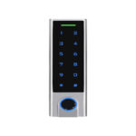
SECO-LARM SK-2612-SFSQ Fingerprint Reader and Keypad

Product Information
Fingerprint Reader and Keypad
Model: SK-2612-SFSQ
Specifications
- Operating voltage: 12VDC
- Current: 60mA @ 12VDC (Standby), 210mA @ 12VDC (Active)
- Outputs: Form C Outputs, Alarm
- Wiegand Inputs: Wiegand, Egress, Door sensor
- Enclosure material: 18.25-oz (516g)
- Operating temperature: -2°F to 158°F
- Operating humidity: 0-95% non-condensing
- Dimensions: 5 3/8″ x 3 3/16″ x 2 1/4″
- Weight: 18.25 oz (516g)
Product Usage Instructions
Mounting the Fingerprint Reader and Keypad
- Drill 2 mounting holes 3 1/4″ (83mm) apart according to the mounting diagram.
- Secure the device using the provided mounting screws and plastic screw anchors.
Wiring Guide
Follow the wiring diagram provided in the manual to connect the device to power, alarm, egress button, door sensor, and output relay.
Programming Instructions
- Enter base programming mode using the factory default master programming code.
- Set a new master programming code (6 digits) following the instructions.
- Add user fingerprints to the keypad for operation.
Frequently Asked Questions (FAQ)
- Q: What should I do if the LED on the reader is flashing red?
A: A flashing red LED indicates that the device has entered programming mode. Ensure not to disconnect the reader from power during this mode to avoid memory errors. - Q: How do I add user fingerprints to operate the output?
A: To add user fingerprints, follow the instructions provided in the manual under the Programming Tips section. User fingerprints can be added repeatedly in succession.
The ENFORCER Fingerprint Reader and Keypad is an advanced security solution that offers both efficiency and convenience. This versatile device can function as a stand-alone controller or a Wiegand reader.
- 12VDC Operation
- Low current draw – 210mA max.
- Form C relay output – 2A@12VDC
- Adjustable output – 1~99 seconds or toggle
- Built-in tamper alarm and external alarm output
- Up to 1,000 users
- Door-propped-open / door-forced open alarm
- Outdoor rated – IP66 weatherproof
- Can serve as Wiegand reader, output – 26~37 bits
- 2-Door interlock
- 500 DPI Optical fingerprint reader with illuminated fingerprint window
- Fingerprint identification time – ≤1 second
- Fingerprint false acceptance rate – ≤0.01%
- Fingerprint false rejection rate – ≤0.1%
Parts List
- 1x Fingerprint reader and keypad
- 1x Diode
- 2x Mounting screws
- 1x Security star wrench
- 2x Plastic screw anchors
- 1x Manual
Specifications
| Operating voltage | 12VDC | |
| Current draw | Standby | 60mA@12VDC |
| Active | 210mA@12VDC (max.) | |
| Outputs | Form C | 2A@12VDC |
| Alarm | Transistor ground, 2A@12VDC | |
| Wiegand | 26~37 bits | |
| Inputs | Wiegand | 26~37 bits, PIN input – 4, 8, or 10 bits |
| Egress | N.O. Ground | |
| Door sensor | N.C. Ground | |
| Enclosure material | Zinc alloy | |
| Operating temperature | -40°~140° F (-40°~60° C) | |
| Operating humidity | 20~90% non-condensing | |
| Dimensions | 21/4″x53/8″x1″ (58x137x26 mm) | |
| Weight | 18.25-oz (516g) | |
Overview

Mounting Diagram

Quick Install Guide
For experienced installers looking to do a basic installation and programming of the reader, but for in-depth installation and programming instructions, see Table of Contents on pg. 5
Quick Wiring Guide

NOTE: To protect the relay, you must install the enclosed diode—with the cathode (striped end![]() ) toward the positive side—for DC powered locks OR install the varistor (MOV, not supplied)
) toward the positive side—for DC powered locks OR install the varistor (MOV, not supplied)![]() for AC powered locks and for electromagnetic locks unless your lock has a diode/MOV built in (all SECO-LARM electromagnetic locks have built-in protection). Do not install both diode and MOV. Failure to use these as directed will void the warranty.
for AC powered locks and for electromagnetic locks unless your lock has a diode/MOV built in (all SECO-LARM electromagnetic locks have built-in protection). Do not install both diode and MOV. Failure to use these as directed will void the warranty.
Programming Tips
- Master programming code (6 digits) should be programmed before any other programming.
- A steady red LED indicates that the reader is powered on and ready. The LED will change to flashing red and a single beep will sound to indicate the device has entered programming mode.
- A steady orange LED indicates that the reader is in a function programming mode.
- Do not disconnect the reader from power while in programming mode. Doing so may cause a memory error.
- Note that, in programming instructions, programming entry actions or options other than specific keystrokes are enclosed within the parentheses, while factory defaults are enclosed within square brackets.
Quick Programming Instructions
Follow the instructions below if the following covers your needs:
- Programming a new master code
- Programming a fingerprint to the first available ID
- Set the output time
- Enter base programming mode:

NOTE: this is the factory default master programming code.
 - Set the new master programming code (6 digits):
0 (the new master code) # (repeat the new master code) #
NOTE: The master code must be 6 digits and not the same as any code. - Set a user fingerprint to operate the output (unlock the door) 1: (fingerprint) (repeat fingerprint), after the user fingerprints are added to the keypad, press #
NOTE: User fingerprints can be added repeatedly in succession. - Set the output time (skip this step if the default value of 5 seconds is acceptable): 3 (1~99) #
NOTE: The delay time is 1~99 seconds - Exit programming mode: *
NOTE: One short beep indicates that the reader has exited programming mode.
- Enter base programming mode:
Important Notes
IF USING THE READER WITH A MECHANICALLY OPERATED DOOR OR GATE, MOUNT THE UNIT AT LEAST 15′ (5m) FROM THE DOOR OR GATE TO PREVENT USERS FROM BEING CRUSHED OR PINNED. FAILURE TO DO SO MAY RESULT IN SERIOUS INJURY OR DEATH.
- Always disconnect the power before servicing the reader. Do not apply power until all connection wiring is completed.
- The reader must be properly grounded. Use a minimum 22AWG wire connected to the common ground wire. Failure to do so may damage the unit.
- All wiring and programming should be done by a professional installer to reduce the risk of improper installation.
- The user’s operating guide for this reader is located on pg.16 of this manual. Be sure to store this manual in a safe place for future reference.
LED Indicators and Device Sounds
| Status | Sounds | LED |
| Power on in standby mode | – | Red steady |
| In programming mode | 1 Beep | Red flashing |
| In function programming mode | 1 Beep | Orange steady |
| Exit programming mode | 1 Beep | Red steady |
| Successful operation | 1 Beep | Green flash once |
| Unsuccessful operation | 3 Beep | Red flashes 3 times |
| Built-in alarm | Rapid beeping* | Red flashing rapidly |
*De-activate the built-in alarm by entering a valid master or user credential (fingerprint or PIN).
Wiring Chart
| Color | Function | Description |
| Red | Power (+) | Connect to +12VDC power supply |
| Black | Ground (-) | Connect to Ground |
| Yellow | Egress Input | N.O. Pushbutton contact to the ground. Press the button to activate the output |
| Brown | Door Sensor | Connect to a magnetic contact or door sensor (connect to the ground if unused) |
| Blue | Output N.O. | NO/NC/COM, relay output, max. 2A@12VDC |
| Purple | Output COM | |
| Orange | Output N.C. | |
| Gray | Alarm Output | Transistor ground output, max. 2A@12VDC |
| Green | Data 0 | Wiegand controller |
| White | Data 1 | Wiegand controller |
NOTE: To protect the relay, you must install the enclosed diode—with the cathode (striped end ![]() ) toward the positive side—for DC-powered locks OR a varistor (MOV, not supplied)
) toward the positive side—for DC-powered locks OR a varistor (MOV, not supplied) ![]() for AC-powered locks and for electromagnetic locks unless your lock has a diode/MOV built in (all SECO-LARM electromagnetic locks have built-in protection). Do not install both diode and MOV. Failure to use these as directed will void the warranty.
for AC-powered locks and for electromagnetic locks unless your lock has a diode/MOV built in (all SECO-LARM electromagnetic locks have built-in protection). Do not install both diode and MOV. Failure to use these as directed will void the warranty.
Installation
- Find a suitable location at a height convenient to most users.
- Remove the security screw from the bottom of the fingerprint reader/keypad using the included security wrench (Fig. 1).
- Carefully remove the reader from the housing base.
- Using the housing base as a template, mark the holes needed for the wiring and mounting screws and drill the needed holes (Fig. 1). Ensure that the wiring hole is large enough to allow the wiring to be pushed in without crimping.
- Run the wiring through the wall to the wiring hole in the wall and carefully push the wires through the hole in the wall and through the hole in the base.
 Install the base using the included mounting screws and mounting screw anchors (if necessary).
Ensure the correct orientation as shown in Fig. 1 on pg. 6.
NOTE: For a weatherproof installation, add a bead of silicone sealant (not included) around the base where it means the wall before attaching.- Connect all wires according to the Wiring Chart on pg. 6.
- Reattach the reader starting from the tab at top of the base and then sliding into position.
- Reinstall the security screw to secure the installation.
Programming Functions and Defaults
| Function Code | Description | Basic Formula | Default Values | Pg. # |
| 0 | Master code | 0 (master code) # (master code) # |
[123456] | 8 |
| 1 | Add users | 1 (fingerprint)(repeat fingerprint) | N/A | 9~10 |
| 2 | Delete users | 2 (fingerprint) | N/A | 10 |
| 3 | Output mode/duration | 3 (1~99) # | [5] Momentary, 5 seconds | 11 |
| 4 | Access mode | 4 (1~4) # OR 4 5 (2~8) #* | [4] PIN or fingerprint | 8 |
| 5 | External alarm/duration | 5 (1~3) # | [1] On, 1 minute | 11 |
| 6 6 |
Wrong credential/PIN lockout Door-propped-open / Door-forced-open alarm | 6 (0~2) # 6 (3~4) # |
[0] Disabled [3] Disabled |
12 12 |
| 7 7 7 |
Two-door Interlock Tamper Alarm Operation mode |
7 (0 or 1) # 7 (2 or 3) # 7 (4 or 5) # |
[0] OFF [3] ON [4] Stand-alone / controller |
13 11 8 |
| 8 8 8 |
Wiegand format Wiegand input bits Device ID |
8 (26~44) # 8 (4 or 8 or 10) # 8 1 (00 ~ 99) # |
[26] [4] [00] Enabled | 14 14 14~15 |
*The second option is for multi-users.
Initial Programming Steps
Programming Tips
- Master programming code (6 digits) should be programmed before any other programming.
- A steady red LED indicates that the reader is powered on and ready. The LED will change to flashing red and a single beep will sound to indicate the device has entered programming mode.
- A steady orange LED indicates that the reader is in a function programming mode.
- Do not disconnect the reader from power while in programming mode. Doing so may cause a memory error.
- Note that, in programming instructions, programming entry actions or options other than specific keystrokes are enclosed within the parentheses, while factory defaults are enclosed within square brackets.
Programming the Master Code
- Enter programming mode: * (master code) #
NOTE: The master code factory default is 123456. - Set the new master code: 0 (new master code) # (repeat the new master code) #
NOTE: The master code must be 6 digits. - Exit programming mode: *
Setting the Reader Operation Mode
- Enter programming mode: * (master code) #
- Standalone: 74# [default]
OR
Wiegand Reader mode:57# - Exit programming mode: *
Programming the Access Mode
- Enter programming mode: * (master code) #
- Fingerprint Access: 41#
OR
Pin Access: 42#
OR
Fingerprint + PIN access: 43#
NOTE: Fingerprint and PIN must share the same UserID
OR
Fingerprint or PIN access: 44# [default] OR
Multi-User access:45 (2~8) #
NOTES- Where 2~8 is the number of users required in order to gain access.
- In multi-user mode, the elapsed time between each user input must not exceed 5 seconds, otherwise the device will return to standby, and the process must start again.
- Exit programming mode: *
Adding Users
User Types, ID Numbers, PIN Codes
| User Type | ID Numbers Available |
| User ID | 1~1,000 |
| Master Add Fingerprint ID | 1001 |
| Master Delete Fingerprint ID | 1002 |
Users are also assigned a PIN of 4~6 digits.
A single User ID can be associated with one PIN and one fingerprint.
IMPORTANT: Recording the user ID for all credentials is important as it is required for modifying the user list.
Adding a Fingerprint User
- Enter programming mode: * (master code) #
- There are several options:
- Add fingerprint using Auto ID: 1 (fingerprint) (repeat fingerprint) #
NOTE: Additional fingerprints can be added in succession before pressing # .
OR - Add fingerprints using specific user ID: 1 (user ID) # (fingerprint) (repeat fingerprint)
NOTE: User ID, any number 1~1,000
IMPORTANT NOTES:
- Use option a with caution if you want to record user IDs, since fingerprints will be assigned the next available user ID.
- In programming mode, when scanning a fingerprint, a short beep and a green flash of the LED will indicate that the fingerprint has been successfully read. If you hear multiple beeps and a flashing red LED, the fingerprint has been rejected or was not successfully read.
- Add fingerprint using Auto ID: 1 (fingerprint) (repeat fingerprint) #
- Exit programming mode: *
Adding a PIN User
- Enter programming mode: *(master code) #
- Add PIN using specific user ID: 1 (user ID) # (PIN) #
NOTE: user ID: any number 1~1,000 - Exit programming mode: *
NOTE: PIN 4~6 digits.
Adding a Fingerprint + PIN User
For Fingerprint + PIN Access or Fingerprint or PIN Access, to assign a user both a fingerprint and PIN, simply add a Fingerprint user and a PIN user, using the same user ID for both.
Adding a Master Add Fingerprint
NOTE: Programming a new Master Fingerprint will overwrite the previous one.
ID limited to 1001.
- Enter programming mode: * (master code) #
- Add fingerprint:
 (fingerprint) (repeat fingerprint)
 - Exit programming mode: *
Adding a Master Delete Fingerprint
ID limited to 1002.
- Enter fingerprint mode: * (master code) #
- Add fingerprint:
 (fingerprint) (repeat fingerprint)
 - Exit programming mode: *
Deleting Users
- Enter programming mode: *(master code) #
- Delete by User ID: 2 (user ID) #
OR
Delete by fingerprint: 2 (fingerprint) (repeat fingerprint)
OR
Delete all users: 2 (master code) # - Exit programming mode: *
Adding/Deleting Users with the Master Fingerprints
Master Fingerprints offers another way to add or delete users without the master code. Not recommended if you are recording user IDs since users will be assigned the next available ID.
Add Fingerprint User
- Scan Master Add Fingerprint
- Scan user fingerprint twice
- Repeat step 2 for additional users
- Scan Master Add Fingerprint again to complete
NOTE: When scanning a fingerprint to add or delete, a short beep and a green flash of the LED will indicate that the fingerprint has been successfully read. If you hear multiple beeps and a flashing red LED, the fingerprint has been rejected or was not successfully read.
Delete Fingerprint User
- Scan Master Delete Fingerprint
- Scan user fingerprint
- Repeat step 2 for additional users
- Scan Master Delete Fingerprint again to complete
Programming the Output Mode and Duration
- Enter programming mode: * (master code) #
- Momentary output mode: 3 (1~99) #
NOTE: Duration is 1~99 seconds [default: 5 seconds].
OR
Toggle mode: 30# - Exit programming mode: *
Programming the External Alarm Output
When the reader is programmed in stand-alone mode, the external alarm is triggered by the tamper alarm, and, if enabled, by the wrong-credential alarm and door-propped-open / door-forced-open alarm.
- Enter programming mode: * (master code) #
- Set duration: 5 (1~3) #
NOTE: Where 1~3 is minutes, duration [default: ON, 1 min] - Exit programming mode : *
NOTE: When the alarm is triggered, it can be disabled by any of the following:
- Master code) #
- Scanning the master add / delete finger
- Scanning any valid user finger
- Entering any valid user PIN
Programming Tamper Alarm
The tamper alarm will activate when the keypad is detached from the base housing.
- Enter programming mode: * (master code) *
OFF: 72#
OR
ON: 73#(default) - Exit programming mode: *
Programming Wrong Credential Lockout/Alarm
This setting tells the reader what to do after 10 failed entry attempts. [Default OFF]
- Enter programming mode: * (master code) #
- Lockout OFF: 60# [default]
OR
Lockout ON: 61#
NOTE: This locks the reader for 10 minutes when triggered and cannot be disabled for the duration.
OR
Lockout ON with Alarm: 62#
NOTE: The alarm duration will follow the global alarm settings, duration [default: 1 min]. However, if the global settings are set to OFF (i.e. duration: 0), those settings will override this and the alarm will not sound (see Programming the External Alarm Output, ) - Exit programming mode: *
Door-Propped-Open / Door Forced-Open Alarm
This feature requires a magnetic contact (not included) or a lock with a built-in sensor connected to the brown wire. If the door is left open longer than 1 minute or if the door is forced open, the keypad’s internal notification will sound and the external alarm according to its settings (see Programming the External Alarm Output, pg. 11) as a reminder. To stop the notification, either close the door, enter the master code, scan a master fingerprint, or other valid user fingerprint/PIN.
- Enter programming mode: * (master code) #
Disable: 63# [default] OR
Enable: 64#
NOTE: The alarm duration follows the overall setting (see Programming the External Alarm Output, ). - Exit programming mode: *
Setting Up a Two-Door Interlock System with Two Readers
In this application, two of the same series of readers are each connected to separate door locks and egress pushbuttons. While one door is open, the other cannot be opened.
Two-Door Interlock System Wiring Diagram

NOTE: To protect the relay, you must install the enclosed diode—with the cathode (striped end ![]() ) toward the positive side—for DC powered locks OR install a varistor (MOV, not supplied)
) toward the positive side—for DC powered locks OR install a varistor (MOV, not supplied)![]() for AC powered locks and for electromagnetic locks unless your lock has a diode/MOV built in (all SECO-LARM electromagnetic locks have built-in protection). Do not install both diode and MOV. Failure to use these as directed will void the warranty.
for AC powered locks and for electromagnetic locks unless your lock has a diode/MOV built in (all SECO-LARM electromagnetic locks have built-in protection). Do not install both diode and MOV. Failure to use these as directed will void the warranty.
Programming the Interlock System
- Enter programming mode: * (master code) #
Disable: 70#[default] OR
Enable: 71# - Exit programming mode: *
NOTE: While you may wish to do so for convenience, it is not necessary for the two readers to have the same master codes.
Setting Up the Wiegand Reader Mode
The reader can work as a standard Wiegand reader with a controller. Be sure to set the reader operation mode to Wiegand reader mode.
- Enter programming mode: *(master code) #
- Wiegand reader mode: 75#
- Exit programming mode: *
Connect the reader and controller as in the diagram in Fig. 3.

Wiegand Output Bits / Format
Set the Wiegand output bits/format according to the input format of the controller.
- Enter programming mode:* (master code) #
- Set output format: 8 (26~44) # [default: 26]
OR
Disable Wiegand output: 80 - Exit programming mode: *
Pin Input Bits
- Enter programming mode: * (master code) #
- Set PIN input bits: 8 (4 or 8 or 10) # [default: 4 bits]
- Exit programming mode: *
Programming a Fingerprint from the Reader
- To add fingerprints, the keypad must be in standalone mode: 74#
NOTE: This product can use fingerprints as a virtual proximity card, a Wiegand data stream to the Wiegand controller. - Enter programming mode: * (Master Code) #
- Enable Device ID: 81 (01 ~ 99) #
- Add fingerprint via user ID: 1 (user ID) # (fingerprint) (repeat fingerprint)
NOTE: User ID, any number 1~1000 - Exit programming mode: *
Wiegand Data Transmission Format
A scanned finger or entered PIN becomes a Wiegand data stream to the Wiegand controller. The Wiegand controller interprets the Weigand data stream as a proximity card.
Fingerprint Example
- Device ID:99
- Fingerprint user ID: 3
- Wiegand data sent to the controller: 099,00003
PIN Example
- Device ID:99
- User inserts PIN:

- Wiegand data sent to the controller: 099,05555
NOTE: If a user enters a PIN of 5-digits or greater, the Device ID will be ignored.
Example 1
- Device ID: 99
- User inserts PIN:

- Wiegand data stream sent to the controller: 000,55555
Example 2
- Device ID: 99
- User inserts PIN:

- Wiegand data stream sent to the controller: 005,55555
Resetting the Reader to Factory Default
When resetting to factory default, user information is retained. You may also program new Master fingerprint. To reset the reader to factory default settings, follow steps 1~4 below.
- Power off the reader.
- Hold down the egress (Request-to-Exit, RTE) button and power the reader on, continuing to hold down the egress button until you hear 2 beeps and the LED turns orange.
NOTE: If no egress button is installed, use a small jumper wire to momentarily connect the yellow and black wires. - Release the egress button.
- If you only need to reset the reader to factory default, wait until the LED changes to red (about 30 seconds) indicating that the reset has completed successfully.
- If you need to program a new Master fingerprint, within 30 seconds scan the Master Add fingerprint twice, then the Master Delete fingerprint twice. The LED will change to red indicating that the reset has completed successfully.
Troubleshooting
Unit fails to accept a new fingerprint
- Ensure the User ID assigned is between 1 and 1000
- Ensure the User ID is not already assigned to another user
Unit fails to accept a new PIN
- Ensure the User ID assigned is between 1 and 1000.
- Ensure the PIN is between 4~6 digits long and not already assigned to another user.
Unit fails to read a programmed fingerprint
- Ensure the finger being presented is the same finger that was originally programmed.
- Press the finger evenly on the central area of the reader.
- Ensure the reader window is clean.
Unit fails to respond to a programmed fingerprint or PIN
- Ensure the unit is in standby mode by pressing the * key until the LED becomes steady red
User Operation of the Reader
Depending on access mode setup, to activate the relay, the user must either:
- Present a fingerprint
- Enter a PIN
- Present a fingerprint + a PIN
The user should hear 1 beep and the status LED should turn green to indicate that the credentials are accepted, and the door is unlocked. Present a valid PIN or fingerprint to silence an alarm (except for duress alarms).
NOTE: An alarm (except duress alarms) can be disabled by a valid PIN or fingerprint (unless Access Mode is set to Fingerprint+PIN or Multi-User Access).
FCC COMPLIANCE STATEMENT
THIS DEVICE COMPLIES WITH PART 15 OF THE FCC RULES.
OPERATION IS SUBJECT TO THE FOLLOWING TWO CONDITIONS:
- THIS DEVICE MAY NOT CAUSE HARMFUL INTERFERENCE AND
- THIS DEVICE MUST ACCEPT ANY INTERFERENCE RECEIVED, INCLUDING INTERFERENCE THAT MAY CAUSE UNDESIRED OPERATION.
Notice: The changes or modifications not expressly approved by the party responsible for compliance could void the user’s authority to operate the equipment.
IMPORTANT NOTE: To comply with the FCC RF exposure compliance requirements, no change to the antenna or the device is permitted. Any change to the antenna or the device could result in the device exceeding the RF exposure requirements and void user’s authority to operate the device.
IMPORTANT WARNING: For a weather-resistant installation, ensure that the unit is installed in a waterproof back box, and that the faceplate and faceplate screws are properly sealed. Incorrect mounting may lead to exposure to rain or moisture inside which could cause a dangerous electric shock, damage the device, and void the warranty. Users and installers are responsible for ensuring that this product is properly installed and sealed.
IMPORTANT: Users and installers of this product are responsible for ensuring that the installation and configuration of this product complies with all national, state, and local laws and codes. SECO-LARM will not be held responsible for the use of this product in violation of any current laws or codes.
California Proposition 65 Warning: These products may contain chemicals which are known to the State of California to cause cancer and birth defects or other reproductive harm. For more information, go to www.P65Warnings.ca.gov.
WARRANTY: This SECO-LARM product is warranted against defects in material and workmanship while used in normal service for one (1) year from the date of sale to the original customer. SECO-LARM’s obligation is limited to the repair or replacement of any defective part if the unit is returned, transportation prepaid, to SECO-LARM. This Warranty is void if damage is caused by or attributed to acts of God, physical or electrical misuse or abuse, neglect, repair or alteration, improper or abnormal usage, or faulty installation, or if for any other reason SECO-LARM determines that such equipment is not operating properly as a result of causes other than defects in material and workmanship. The sole obligation of SECO-LARM and the purchaser’s exclusive remedy, shall be limited to the replacement or repair only, at SECO-LARM’s option. In no event shall SECO-LARM be liable for any special, collateral, incidental, or consequential personal or property damage of any kind to the purchaser or anyone else.
NOTICE: The SECO-LARM policy is one of continual development and improvement. For that reason, SECO-LARM reserves the right to change specifications without notice. SECO-LARM is also not responsible for misprints. All trademarks are the property of SECO-LARM U.S.A., Inc. or their respective owners. Copyright © 2024 SECO-LARM U.S.A., Inc. All rights reserved.
SECO-LARM ® U.S.A., Inc.
16842 Millikan Avenue, Irvine, CA 92606
- Website: www.seco-larm.com
- Phone: 949-261-2999 | 800-662-0800
- Email: sales@seco-larm.com
Documents / Resources
 |
SECO-LARM SK-2612-SFSQ Fingerprint Reader and Keypad [pdf] Instruction Manual SK-2612-SFSQ, SK-2612-SFSQ Fingerprint Reader and Keypad, SK-2612-SFSQ, Fingerprint Reader and Keypad, Reader and Keypad, and Keypad, Keypad |