Schneider Electric Modicon M580 Edge Compute Node Module
Specifications
- Product Name: Modicon M580 BMEECN0100H
- Model: Edge Compute Node Module
- Version: EIO0000005001.00
- Manufacturer: Schneider Electric
- Website: www.se.com
Product Information
The Modicon M580 BMEECN0100H Edge Compute Node Module is a versatile device designed for installation and configuration in industrial automation systems. It provides advanced computing capabilities for data processing and control applications.
Safety Information
Before proceeding with the installation and configuration of the Edge Compute Node Module, please ensure that you have read and understood all safety instructions provided in the user manual.
Before You Begin
Make sure to gather all necessary tools and equipment as outlined in the user manual. Ensure that power to the system is turned off before starting any installation procedures.
Start-up and Test
Follow the step-by-step instructions in the user manual to properly start up and test the Edge Compute Node Module. This includes verifying connections, checking for any error indicators, and ensuring proper initialization.
Operation and Adjustments
Once the module is successfully installed and tested, refer to the user manual for guidance on operating the device and making any necessary adjustments for optimal performance.
FAQ
Q: Can the Edge Compute Node Module be used in harsh industrial environments?
A: Yes, the Edge Compute Node Module is designed to withstand harsh industrial conditions and operates reliably in such environments.
Q: How often should firmware upgrades be performed?
A: Firmware upgrades should be performed as recommended by Schneider Electric to ensure compatibility and access to the latest features and enhancements.
Modicon M580 BMEECN0100H
Edge Compute Node Module Installation and Configuration Guide
Original instructions 02/2024 EIO0000005001.00
Legal Information
The information provided in this document contains general descriptions, technical characteristics and/or recommendations related to products/solutions.
This document is not intended as a substitute for a detailed study or operational and site-specific development or schematic plan. It is not to be used for determining suitability or reliability of the products/solutions for specific user applications. It is the duty of any such user to perform or have any professional expert of its choice (integrator, specifier or the like) perform the appropriate and comprehensive risk analysis, evaluation and testing of the products/solutions with respect to the relevant specific application or use thereof.
The Schneider Electric brand and any trademarks of Schneider Electric SE and its subsidiaries referred to in this document are the property of Schneider Electric SE or its subsidiaries. All other brands may be trademarks of their respective owner.
This document and its content are protected under applicable copyright laws and provided for informative use only. No part of this document may be reproduced or transmitted in any form or by any means (electronic, mechanical, photocopying, recording, or otherwise), for any purpose, without the prior written permission of Schneider Electric.
Schneider Electric does not grant any right or license for commercial use of the document or its content, except for a non-exclusive and personal license to consult it on an “as is” basis.
Schneider Electric reserves the right to make changes or updates with respect to or in the content of this document or the format thereof, at any time without notice.
To the extent permitted by applicable law, no responsibility or liability is assumed by Schneider Electric and its subsidiaries for any errors or omissions in the informational content of this document, as well as any non-intended use or misuse of the content thereof.
UNGUARDED EQUIPMENT
 · Do not use this software and related automation equipment on equipment which does not have point-of-operation protection.
· Do not reach into machinery during operation.
Failure to follow these instructions can result in death, serious injury, or equipment damage.
This automation equipment and related software is used to control a variety of industrial processes. The type or model of automation equipment suitable for each application will vary depending on factors such as the control function required, degree of protection required, production methods, unusual conditions, government regulations, etc. In some applications, more than one processor may be required, as when backup redundancy is needed.
Only you, the user, machine builder or system integrator can be aware of all the conditions and factors present during setup, operation, and maintenance of the machine and, therefore, can determine the automation equipment and the related safeties and interlocks which can be properly used. When selecting automation and control equipment and related software for a particular application, you should refer to the applicable local and national standards and regulations. The National Safety Council’s Accident Prevention Manual (nationally recognized in the United States of America) also provides much useful information.
In some applications, such as packaging machinery, additional operator protection such as point-of-operation guarding must be provided. This is necessary if the operator’s hands and other parts of the body are free to enter the pinch points or other hazardous areas and serious injury can occur. Software products alone cannot protect an operator from injury. For this reason the software cannot be substituted for or take the place of point-of-operation protection.
Ensure that appropriate safeties and mechanical/electrical interlocks related to point-of-operation protection have been installed and are operational before placing the equipment into service. All interlocks and safeties related to point-ofoperation protection must be coordinated with the related automation equipment and software programming.
NOTE: Coordination of safeties and mechanical/electrical interlocks for pointof-operation protection is outside the scope of the Function Block Library, System User Guide, or other implementation referenced in this documentation.
6
EIO0000005001.00
Safety Information
Start-up and Test
Edge Compute Node Module
Before using electrical control and automation equipment for regular operation after installation, the system should be given a start-up test by qualified personnel to verify correct operation of the equipment. It is important that arrangements for such a check are made and that enough time is allowed to perform complete and satisfactory testing.
WARNING
EQUIPMENT OPERATION HAZARD
 · Verify that all installation and set up procedures have been completed.
· Before operational tests are performed, remove all blocks or other temporary holding means used for shipment from all component devices.
· Remove tools, meters, and debris from equipment.
Failure to follow these instructions can result in death, serious injury, or equipment damage.
Follow all start-up tests recommended in the equipment documentation. Store all equipment documentation for future references.
Software testing must be done in both simulated and real environments.
Verify that the completed system is free from all short circuits and temporary grounds that are not installed according to local regulations (according to the National Electrical Code in the U.S.A, for instance). If high-potential voltage testing is necessary, follow recommendations in equipment documentation to prevent accidental equipment damage.
Before energizing equipment:
· Remove tools, meters, and debris from equipment.
· Close the equipment enclosure door.
· Remove all temporary grounds from incoming power lines.
· Perform all start-up tests recommended by the manufacturer.
Operation and Adjustments
 The following precautions are from the NEMA Standards Publication ICS 7.11995:
(In case of divergence or contradiction between any translation and the English original, the original text in the English language will prevail.)
· Regardless of the care exercised in the design and manufacture of equipment or in the selection and ratings of components, there are hazards that can be encountered if such equipment is improperly operated.
· It is sometimes possible to misadjust the equipment and thus produce unsatisfactory or unsafe operation. Always use the manufacturer’s instructions as a guide for functional adjustments. Personnel who have access to these adjustments should be familiar with the equipment manufacturer’s instructions and the machinery used with the electrical equipment.
· Only those operational adjustments required by the operator should be accessible to the operator. Access to other controls should be restricted to prevent unauthorized changes in operating characteristics.
EIO0000005001.00
7
Edge Compute Node Module
About the Book
About the Book
Document Scope
This manual describes the features and use of the BMEECN0100H Edge Compute Node module v 01.02.03 for Modicon M580.
NOTE: The specific configuration settings contained in this guide are intended to be used for instructional purposes only. The settings required for your specific configuration may differ from the examples presented in this guide.
Validity Note
This document is valid for the EcoStruxureTM Control Expert 15.1 Hotfix 013 (ControlExpert_V151_HF013).
The characteristics of the products described in this document are intended to match the characteristics that are available on www.se.com. As part of our corporate strategy for constant improvement, we may revise the content over time to enhance clarity and accuracy. If you see a difference between the characteristics in this document and the characteristics on www.se.com, consider www.se.com to contain the latest information.
Available Languages of this Document
The information contained herein is available in these languages: · English (EIO0000005001) · French (EIO0000005002) · German (EIO0000005003) · Italian (EIO0000005004) · Spanish (EIO0000005005) · Chinese (EIO0000005006) NOTE: After clicking one of the above download links, you may need to select your country before you can download the document.
Related Documents
Title of documentation Modicon M580 Standalone, System Planning Guide for Frequently Used Architectures
Modicon M580, System Planning Guide for Complex Topologies
Modicon M580, Hardware, Reference Manual
Reference number
HRB62666 (ENG) HRB65318 (FRE) HRB65319 (GER) HRB65320 (ITA) HRB65321 (SPA) HRB65322 (CHS)
NHA58892 (ENG) NHA58893 (FRE) NHA58894 (GER) NHA58895 (ITA) NHA58896 (SPA) NHA58897 (CHS)
EIO0000001578 (ENG) EIO0000001579 (FRE) EIO0000001580 (GER) EIO0000001582 (ITA) EIO0000001581 (SPA) EIO0000001583 (CHS)
8
EIO0000005001.00
About the Book
Edge Compute Node Module
Title of documentation Modicon M580, M340, and X80 I/O Platforms, Standards and Certifications
Modicon X80 Racks and Power Supplies, Hardware, Reference Manual
Reference number
EIO0000002726 (ENG) EIO0000002727 (FRE) EIO0000002728 (GER) EIO0000002730 (ITA) EIO0000002729 (SPA) EIO0000002731 (CHS)
EIO0000002626 (ENG) EIO0000002627 (FRE) EIO0000002628 (GER) EIO0000002630 (ITA) EIO0000002629 (SPA) EIO0000002631 (CHS)
Product Related Information
DANGER
HAZARD OF ELECTRIC SHOCK, EXPLOSION, OR ARC FLASH
· Disconnect all power from all equipment, including connected devices, prior to removing any covers or doors or installing or removing any accessories, hardware, cables, or wires except under the specific conditions specified in the appropriate hardware guide for this equipment.
· Always use a properly rated voltage-sensing device to confirm the power is off where and when indicated.
· Replace and secure all covers, accessories, hardware, cables, and wires and confirm that a proper ground connection exists before applying power to the unit.
· Use only the specified voltage when operating the equipment and any associated products.
Failure to follow these instructions will result in death or serious injury.
WARNING
LOSS OF CONTROL · Perform a Failure Mode and Effects Analysis (FMEA), or equivalent risk
analysis, of your application, and apply preventive and detective controls before implementation.
· Provide a fallback state for undesired control events or sequences.
· Provide separate or redundant control paths wherever required.
· Supply appropriate parameters, particularly for limits.
· Review the implications of transmission delays and take actions to mitigate them.
· Review the implications of communication link interruptions and take actions to mitigate them.
· Provide independent paths for control functions (for example, emergency stop, over-limit conditions, and error conditions) according to your risk assessment, and applicable codes and regulations.
· Apply local accident prevention and safety regulations and guidelines.1
· Test each implementation of a system for proper operation before placing it into service.
Failure to follow these instructions can result in death, serious injury, or equipment damage.
1 For additional information, refer to NEMA ICS 1.1 (latest edition), Safety Guidelines for the Application, Installation, and Maintenance of Solid State Control and to NEMA ICS 7.1 (latest edition), Safety Standards for Construction and Guide for Selection, Installation and Operation of Adjustable-Speed Drive Systems or their equivalent governing your particular location.
EIO0000005001.00
9
Edge Compute Node Module
About the Book
WARNING
UNINTENDED EQUIPMENT OPERATION · Only use software approved by Schneider Electric for use with this
equipment. · Update your application program every time you change the physical
hardware configuration. Failure to follow these instructions can result in death, serious injury, or equipment damage.
The examples in this document are given for information only.
WARNING
UNINTENDED EQUIPMENT OPERATION
Adapt examples that are given in this manual to the specific functions and requirements of your industrial application before you implement them.
Failure to follow these instructions can result in death, serious injury, or equipment damage.
Trademarks
QR Code is a registered trademark of DENSO WAVE INCORPORATED in Japan and other countries.
DockerTM is a registered trademark of Docker, Inc.
Information on Non-Inclusive or Insensitive Terminology
As a responsible, inclusive company, Schneider Electric is constantly updating its communications and products that contain non-inclusive or insensitive terminology. However, despite these efforts, our content may still contain terms that are deemed inappropriate by some customers.
Terminology Derived from Standards
The technical terms, terminology, symbols and the corresponding descriptions in the information contained herein, or that appear in or on the products themselves, are generally derived from the terms or definitions of international standards.
In the area of functional safety systems, drives and general automation, this may include, but is not limited to, terms such as safety, safety function, safe state, fault, fault reset, malfunction, failure, error, error message, dangerous, etc.
Among others, these standards include:
Standard IEC 61131-2:2007 ISO 13849-1:2023
EN 61496-1:2013
ISO 12100:2010 EN 60204-1:2006
Description
Programmable controllers, part 2: Equipment requirements and tests.
Safety of machinery: Safety related parts of control systems. General principles for design.
Safety of machinery: Electro-sensitive protective equipment.
Part 1: General requirements and tests.
Safety of machinery – General principles for design – Risk assessment and risk reduction Safety of machinery – Electrical equipment of machines – Part 1: General requirements
10
EIO0000005001.00
About the Book
Edge Compute Node Module
Standard ISO 14119:2013 ISO 13850:2015 IEC 62061:2021 IEC 61508-1:2010 IEC 61508-2:2010
IEC 61508-3:2010 IEC 61784-3:2021 2006/42/EC 2014/30/EU 2014/35/EU
Description
Safety of machinery – Interlocking devices associated with guards Principles for design and selection
Safety of machinery – Emergency stop – Principles for design
Safety of machinery – Functional safety of safety-related electrical, electronic, and electronic programmable control systems
Functional safety of electrical/electronic/programmable electronic safetyrelated systems: General requirements.
Functional safety of electrical/electronic/programmable electronic safetyrelated systems: Requirements for electrical/electronic/programmable electronic safety-related systems.
Functional safety of electrical/electronic/programmable electronic safetyrelated systems: Software requirements.
Industrial communication networks – Profiles – Part 3: Functional safety fieldbuses – General rules and profile definitions.
Machinery Directive
Electromagnetic Compatibility Directive
Low Voltage Directive
In addition, terms used in the present document may tangentially be used as they are derived from other standards such as:
Standard IEC 60034 series IEC 61800 series IEC 61158 series
Description
Rotating electrical machines
Adjustable speed electrical power drive systems
Digital data communications for measurement and control Fieldbus for use in industrial control systems
Finally, the term zone of operation may be used in conjunction with the description of specific hazards, and is defined as it is for a hazard zone or danger zone in the Machinery Directive (2006/42/EC) and ISO 12100:2010.
NOTE: The aforementioned standards may or may not apply to the specific products cited in the present documentation. For more information concerning the individual standards applicable to the products described herein, see the characteristics tables for those product references.
EIO0000005001.00
11
Edge Compute Node Module
Module Characteristics
Module Characteristics
Overview
The following information describes the BMEECN0100H Edge Compute Node (ECN) module with an embedded DockerTM container and access to an OPC UA server.
Module Features
Introduction
This module is a general purpose compute device for Modicon M580 controllers.
This module is an open Linux/ARM powered module including a Docker runtime service and an OPC UA container for accessing the Modicon M580 data dictionary. It is included in the EcoStruxure Control Expert Hardware Catalog in the Communication module group.
For more information on how to access the Hardware Catalog, refer to the EcoStruxureTM Hardware Catalog Manager Operation Guide, How to Launch the Hardware Catalog Manager.
Features
These are the main characteristics of the module: · One-slot X80 module (13 cm) · Dual-core 500 MHz ARM V7 32-bit processor · 1 GB Error Correction Code (ECC) RAM · 8 GB internal storage for user applications* · Front: 1 x 1 Gb/s Ethernet interface · Front: 1 x USB-C host interface (not used) · Front LED display · Operation without batteries · Hot swapping
The module features are: · General: Firmware upgrade using EcoStruxure Automation Device Maintenance, page 73 Firmware integrity verification X Bus backplane port for 24 Vdc power and backplane addressing Docker runtime service running an OPC UA container and an internal virtual network Authentication management: user authentication, page 60 · Communication: Seamless Ethernet backplane communications Ethernet backplane port for Ethernet communication over the local main Ethernet backplane Secure communications through HTTPS
12
EIO0000005001.00
Module Characteristics
Edge Compute Node Module
· Diagnostics: Multiple diagnostic methods, including LEDs, page 65, OPC UA variables and data items, page 68, Syslog, page 70, SNMP, page 72, and OPC UA diagnostics web page Direct and optimized access to EcoStruxure Control Expert data dictionary for mapping between EcoStruxure Control Expert and OPC UA variables, page 32
The module is compatible with: · BMENOC····, BMENUA0100, and BMEECN0100H modules installed into the same backplane · M580 Safety systems as a type 1 non-interfering module as defined by TÜV Rheinland · Modicon M580 standalone controllers (including M580 Safety controller)
* Application Limitations
The maximum Embedded Multimedia Card (eMMC) internal storage for system and user applications is 8 GB.
Control the memory size of your own application(s) as it can impact the stability of the overall system in case there is not enough memory for other system containers.
WARNING
UNINTENDED EQUIPMENT OPERATION
Do not exceed the limit of 8 GB maximum of internal storage for the user applications.
Failure to follow these instructions can result in death, serious injury, or equipment damage.
Environmental Specifications
The BMEECN0100H module operates in these environmental conditions:
Parameter Ambient air temperature for operation Relative humidity IP degree of protection
Value -25…70 °C (-13 … 158 °F) 5…95% at 55 °C (131 °F) IP20
Hot Swapping Considerations
The BMEECN0100H module is a hot swappable device.
Hot swapping is the ability to remove a module from its bus base and then to replace it with an identical module, while the M580 system is powered up, without disrupting the normal operations of the controller. When the electronic module is placed back to its bus base or replaced with another electronic module with the same reference, it starts to operate again.
EIO0000005001.00
13
Edge Compute Node Module
Module Characteristics
DANGER
EXPLOSION OR ELECTRIC SHOCK · Only perform a hot swap operation in locations known and confirmed to be
non-hazardous.
· Only replace an electronic module with an identical reference.
Failure to follow these instructions will result in death or serious injury.
WARNING
LOSS OF CONTROL · Perform a Failure Mode and Effects Analysis (FMEA), or equivalent risk
analysis, of your application, and apply preventive and detective controls before implementation.
· Provide a fallback state for undesired control events or sequences.
· Provide separate or redundant control paths wherever required.
· Supply appropriate parameters, particularly for limits.
· Review the implications of transmission delays and take actions to mitigate them.
· Review the implications of communication link interruptions and take actions to mitigate them.
· Provide independent paths for control functions (for example, emergency stop, over-limit conditions, and error conditions) according to your risk assessment, and applicable codes and regulations.
· Apply local accident prevention and safety regulations and guidelines.1
· Test each implementation of a system for proper operation before placing it into service.
Failure to follow these instructions can result in death, serious injury, or equipment damage.
1 For additional information, refer to NEMA ICS 1.1 (latest edition), Safety Guidelines for the Application, Installation, and Maintenance of Solid State Control and to NEMA ICS 7.1 (latest edition), Safety Standards for Construction and Guide for Selection, Installation and Operation of Adjustable-Speed Drive Systems or their equivalent governing your particular location.
14
EIO0000005001.00
Module Characteristics
Physical Description
Edge Compute Node Module
Introduction
Install the module in a slot that is not reserved for the power supply or controller on a main, local Ethernet backplane.
WARNING
EQUIPMENT OPERATION HAZARD · Verify that the BMEECN0100H module is installed in a slot that is not
reserved for the power supply or controller on a main, local Ethernet backplane. · Use only BMEXBP···· or BMEXBP····H Ethernet backplane. Failure to follow these instructions can result in death, serious injury, or equipment damage.
For a description of supported module placements, including the maximum number of BMEECN0100H modules that can be placed on a backplane, refer to Supported BMEECN0100H Module Configurations, page 36.
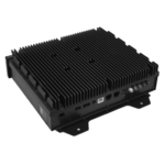
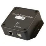
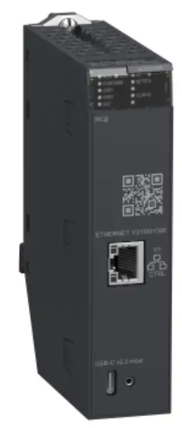
Physical Description
These are the external features of the module:
1 USB Type-C 2.0 port (not used) 2 Control port with Ethernet link and activity LEDs 3 LED display 4 QR code 5 Backplane screw 6 X Bus backplane port 7 Ethernet backplane port 8 Rotary switch For details on the module LED indicators, refer to LED Diagnostics, page 65.
EIO0000005001.00
15
Edge Compute Node Module
Module Characteristics
If the Ethernet port is not enabled, use the stopper that is delivered with each module to help prevent debris from entering the control port:
Module Dimensions
The BMEECN0100H module has the following dimensions:
131 5.16 134.6 5.30
35.7 1.41
32
a 19
86
1.26
0.75
3.39
a DIN-rail depth: the value depends on the DIN-rail type used in your platform. For details, refer to Modicon X80 Racks and Power Supplies Hardware Reference Manual, Mounting the Racks.
16
EIO0000005001.00
Module Characteristics
External Ports
Edge Compute Node Module
The module has these external ports:
Port
Description
Control port
The control port is the single port located on the front of the module. Its features include:
· Capability to disable the control port through EcoStruxure Control Expert.
When the control port is enabled, it is the exclusive interface for BMEECN0100H communications.
· Operating speed up to 1 Gb/s. When operating at the speed of:
1 Gb/s, use only CAT6 copper shielded twisted four-pair cables.
10/100 Mb/s, use CAT5e or CAT6 copper shielded twisted four-pair cables.
· IP stack that supports IPv4 (32 bit) IP addressing:
IPv4 is configured for the module in EcoStruxure Control Expert. For more information, refer to Configuring IP Address Settings, page 40.
If an IP address is not configured in EcoStruxure Control Expert, IPv4 default setting, page 40 is auto-assigned based on the module MAC address.
· HTTPS secure protocol (over IPv4) for firmware upgrade, page 73 and cybersecurity configuration, page 47.
· NTP v4 protocol support (2 servers maximum).
· SNMP v1
· Syslog
Ethernet backplane port
The module Ethernet backplane port supports the IPv4 (32 bit) protocol:
· Operating speed up to 100 Mb/s.
· Exclusive port for non-cybersecurity configuration (IP address, NTP v4, SNMP v1)
· EcoStruxure Control Expert 15.1 Hotfix 013 (ControlExpert_V151_HF013) and any subsequent supporting version(s)
· Fast Device Replacement (FDR) server
· DHCP server
X Bus backplane port
The module uses X Bus backplane communication to: · Receive 24 Vdc power. · Discover the backplane and slot address of the module. NOTE: No other communication is performed through the X Bus backplane port of the module.
EIO0000005001.00
17
Edge Compute Node Module
Rotary Switch
Module Characteristics
A rotary switch is located on the back of the module and it is used to select the module operating mode.
NOTE: A plastic screwdriver is provided for your convenience; use it, or an equivalent, to change the position of the rotary switch. Avoid using metal screwdrivers. The positions on the rotary switch are: · Standard mode (default) · Cybersecurity Reset mode · Advanced mode (not used) For more information on the module operating modes defined by the rotary switch, refer to Operating Modes, page 21.
Cybersecurity Reset
Advanced
Standard
NOTE:
· The rotary switch is not accessible when the module is placed on the backplane.
· When the re-initialization procedure is over (the rotary switch is in the Cybersecurity Reset mode), set the switch back to the Standard mode and restart the device.
BMEECN0100H Firmware Compatibility with EcoStruxure Control Expert
Compatibility
Applications created with EcoStruxure Control Expert are compatible with the module firmware:
Software EcoStruxure Control Expert
M580 firmware EcoStruxure Automation Device Maintenance
Version EcoStruxure Control Expert 15.1 Hotfix 013 (ControlExpert_V151_HF013)
V3.20
>V3.2
18
EIO0000005001.00
Module Characteristics
Module LEDs
Edge Compute Node Module
LED Display
A display panel is located on the front of the module:
These LEDs display information about the module:
LED RUN ERR I/O CONTAINR NETSTS USR1 USR2 SEC CONFIG
Description: Operating condition Detected errors Data communication state State of containers delivered by Schneider Electric Network communication state Not used Not used Cybersecurity status Configuration state
For information on how to use these LED indicators to diagnose the state of the module, refer to LED Diagnostics, page 65.
Control Port LEDs
The control port, on the front of the module, presents two LEDs describing the state of the Ethernet link over the port:
· The ACT LED indicates the presence of Ethernet activity on the port.
· The LNK LED indicates the existence of an Ethernet link and the link speed.
For information on how to use the control port LED indicators to diagnose the state of the module control port, refer to LED Diagnostics, page 65.
EIO0000005001.00
19
Edge Compute Node Module
Standards and Certifications Applied to the Module
Standards and Certifications Applied to the Module
Online Help
From the EcoStruxure Control Expert online help, you can access the standards and certifications that apply to the modules in this product line by referring to the Modicon M580, M340, and X80 I/O Platforms, Standards and Certifications guide.
Download
Click the link that corresponds to your preferred language to download standards and certifications (PDF format) that apply to the modules in this product line:
Title
Modicon M580, M340, and X80 I/O Platforms, Standards and Certifications
Languages
· English: EIO0000002726 · French: EIO0000002727 · German: EIO0000002728 · Italian: EIO0000002730 · Spanish: EIO0000002729 · Chinese: EIO0000002731
20
EIO0000005001.00
Functional Description
Functional Description
Edge Compute Node Module
Overview
The following information describes the functions that the BMEECN0100H Edge Compute Node (ECN) module supports.
Operating Modes
Standard Mode
The Standard mode is the default operating mode of the module. When operating in Standard mode, the module starts communications immediately and can be configured both in the Modicon Edge Compute Module website, page 47 and in EcoStruxure Control Expert, page 40.
Cybersecurity Reset
The Cybersecurity Reset command restores the default configuration settings. It deletes the prior cybersecurity configuration, trust lists, certificates, and rolebased access-control settings. While the process of restoring factory default settings is ongoing, the RUN LED flashes green. After completion of the process, the RUN LED turns to steady green.
Use either the rotary switch or the Modicon Edge Compute Module website, page 47 to set this operating mode.
Rotary Switch: 1. With the module detached from the backplane, set the rotary switch to the Cybersecurity Reset position. NOTE: A plastic screwdriver is provided for your convenience; use it, or an equivalent, to change the position of the rotary switch. Avoid using metal screwdrivers. 2. Install the module in a slot that is not reserved for the power supply or controller on a main, local Ethernet backplane.
WARNING
EQUIPMENT OPERATION HAZARD · Verify that the BMEECN0100H module is installed in a slot that is not
reserved for the power supply or controller on a main, local Ethernet backplane. · Use only BMEXBP···· or BMEXBP····H Ethernet backplane. Failure to follow these instructions can result in death, serious injury, or equipment damage.
For details, refer to Installing the Module, page 37. Upon completion, the RUN LED is steady green, and both the CONTAINR and NETSTS LEDs are steady red. 3. Turn off the power, remove the module from the backplane, set the rotary switch to the Standard mode, and then reinsert the module into the backplane. NOTE: The BMEECN0100H Edge Compute Node is a hot swap electronic module, page 13. For details on the different ways to install and remove the module, refer to Power Consideration, page 38.
EIO0000005001.00
21
Edge Compute Node Module
Functional Description
Website: 1. Connect to the Modicon Edge Compute Module website: type https:// <control port IP address> in your Internet browser, then enter your User Name and Password. For details, refer to Logging into the Module Website, page 47 and Default Username/Password Combination, page 47. 2. In the Modicon Edge Compute Module website, page 47, navigate to PARAMETERS > CONFIGURATION MANAGEMENT > RESET:
3. Click Reset. NOTE: The Reset operation is complete when the RUN LED is steady green, and both the CONTAINR and NETSTS LEDs are steady red.
4. Cycle power to the module in one of these ways: · Turn off power to the module backplane, then turn power back on. · Physically remove the module from the backplane, then re-insert it.
After the Cybersecurity Reset, these conditions apply to the module: · Factory default settings are restored, including the Username/Password default settings. · No customer certificates are retained. NOTE: Reconfigure the Cybersecurity and IP address settings after a Cybersecurity Reset.
Container Presentation
Introduction
This section presents container services supported by the module.
Functional Description
A container is a unit of software that packages the code and its dependencies. In the BMEECN0100H Edge Compute Node, two types of containers are used by the Docker container engine (see the diagram, page 23 below):
· Six containers developed by Schneider Electric
· Containers with applications developed by the user.
The Docker container engine is used for deploying and scaling application containers. For more information on container technology, go to the Docker official website.
For details on OPC UA connection limitations for client containers, refer to General Limitations, page 24.
22
EIO0000005001.00
Functional Description
Architecture
Edge Compute Node Module This diagram presents the BMEECN0100H module architecture:
NOTE: Schneider Electric containers and user containers are connected to each other through a virtual network represented in the above diagram by the black arrow. For details on OPC UA server/client connections, refer to OPC UA Server, page 26.
This table gives the definitions of the terms used in the container architecture diagram:
Term HARDWARE OS
FIRMWARE OS CONTAINER ENGINE CONTAINER SE CONTAINER USER CONTAINER OPC UA SERVER OPC UA CLIENT
Definition
The physical and electronic parts of the module.
An operating system (OS) is a system software that manages the hardware and software resources of the module, and provides common services for computer programs.
Schneider Electric Linux internal processes.
Service for creating, deploying, managing, and scaling application containers.
A container is a standard unit of software that packages the code and its dependencies.
A container developed by Schneider Electric.
A container developed by the user.
An embedded OPC UA server communication stack.
A containerized OPC UA client.
EIO0000005001.00
23
Edge Compute Node Module
OPC UA Services
Functional Description
Overview
This section describes the OPC UA services supported by the OPC UA server used by the BMEECN0100H module.
OPC UA Server Operating Characteristics
Introduction
In this chapter, the OPC UA server characteristics relate to the hardware specifications.
General Limitations
The following general OPC UA server operation limitations apply to the module: · 100,000 nodes maximum to publish in the data access address space of the OPC UA server · 192 MB of the memory allocated to the OPC UA Server NOTE: If one of the limitations mentioned above is exceeded, the server address space state becomes LimitsExceeded.
WARNING
UNINTENDED EQUIPMENT OPERATION Do not exceed the limit of 100,000 nodes to be published in the OPC UA server. Failure to follow these instructions can result in death, serious injury, or equipment damage.
Processor Performance Versus Data Consumption
This table provides the module performance when 1 internal user container is connected to the OPC UA server:
Maximum Number of Read/ Write Data (Measured Time)
300 data (90 ms) 1000 data (210 ms) 1900 data (450 ms)
Maximum Number of Subscription Data (Sampling Equals to Publishing Interval)
BMEECN0100H Processor Consumption
300 data (20 ms)
50 %
1000 data (100 ms)
50 %
1000 data (1 s)
50 %
Processor Performance Versus OPC UA Server Connections
This table provides the module performance when OPC UA clients are connected to the OPC UA server:
Number of OPC UA Client Connections 2
Minimum Fast Sampling/ Publishing Rate 20 ms
BMEECN0100H Processor Consumption 50 %
24
EIO0000005001.00
Functional Description
Edge Compute Node Module
You can connect a maximum of two OPC UA clients with the following limitations: · 1 OPC UA client per container (2 containers maximum); or · 2 OPC UA clients in one container NOTE: If the number of client container connections exceeds the indicated limitations, this can influence the module functioning.
WARNING
UNINTENDED EQUIPMENT OPERATION Do not exceed the limit of 2 OPC UA server connections for client containers. Failure to follow these instructions can result in death, serious injury, or equipment damage.
OPC UA Server Limitations
This table lists the OPC UA server limitations, the context in which they occur, and the consequences if these limitations are exceeded:
Limitation
Cumulative Session Count
Minimum Session Timeout
Cumulative Session Timeout
Maximum Cumulative Subscription Count
Minimum Publishing Interval
Maximum Publishing Interval
Maximum Subscription Lifetime
Maximum Notifications Per Publish
Minimum Sampling Interval
Maximum Message Queue Size
Maximum Cumulative Monitored Items Count
Maximum Subscriptions Per Session
Maximum Monitored Items Count Per Subscription
Value 2
OPC UA Service CreateSession
30 s CreateSession
3600 s CreateSubscription
40 CreateSubscription
20 ms CreateSubscription 10 s CreateSubscription 300 s CreateSubscription 12500 CreateSubscription 20 ms CreateMonitoredtems 100 CreateMonitoredtems 1900 CreateMonitoredtems
2
CreateSubscription
1900 CreateMonitoredtems
Service Parameter N/A
Requested SessionTimeout
Effects Bad_TooManySessions service result code revisedSession timeout
Requested SessionTimeout
revisedSession timeout
N/A
Bad_TooManySubscriptions
service result code
Requested Publishing Interval
revisedPublishingInterval
Requested Publishing Interval
revisedPublishingInterval
Min(Requested Publishing Interval, 3600000) * Requested LifetimeCount maxNotificationsPerPublish
MonitoringParameters. SamplingInterval MonitoringParameters. QueueSize N/A
revisedLifetimeCount
Notifications maximum capacity is (1000/ revisedPublishingInterval) * 1000 notifications per second revisedSampling interval
revisedQueueSize
Bad_TooManyMonitoredItems service result code
N/A
N/A
N/A
N/A
EIO0000005001.00
25
Edge Compute Node Module
Functional Description
NOTE: The time needed to establish the time subscription depends on the number of items and connected clients. NOTE: For a full description of the OPC UA status codes, refer to SIMATIC WinCC Open Architecture Version 3.18 Documentation: OPC UA Status Codes.
OPC UA Server
Introduction
The primary purpose of the module is to provide an OPC UA communication channel over Ethernet between M580 controllers and OPC UA clients. The data of the M580 controller is mapped to variables in the module and made available to OPC UA clients through an OPC UA server communication stack embedded in the module. OPC UA clients connect to the embedded OPC UA server stack using a containerized OPC UA client through the available network.
NOTE:
· The terms of each connection between an OPC UA client and the OPC UA server embedded in the module are determined by the client, which sets the attributes of the connection between the client and server.
· The fast sampling communication mode is activated by default and cannot be deactivated.
· Integrate the OPC UA client into the module (not provided) in order to get the OPC UA server values.
The OPC UA server stack embedded in the module consists of functionalities defined by these terms:
· Profile: a definition of functionality that includes other profiles, facets, conformance groups, and conformance units.
· Facet: defines a partial functionality.
· Conformance Group: a collection of conformance units.
· Conformance Unit: a specific service, for example, read and write.
Supported Profile
The module supports the Embedded 2017 UA Server Profile. For more information, refer to the OPC Foundation website at: http://opcfoundation.org/UAProfile/Server/EmbeddedUA2017.
Supported Facets
The module supports these facets: · Server Category > Facets > Core Characteristics: Core 2017 Server Facet (http://opcfoundation.org/UA-Profile/Server/ Core2017Facet) · Server Category > Facets > Data Access: ComplexType 2017 Server Facet (http://opcfoundation.org/UA-Profile/ Server/ComplexTypes2017) Data Access Server Facet (http://opcfoundation.org/UA-Profile/Server/ DataAccess) Embedded DataChange Subscription Server Facet (http:// opcfoundation.org/UA-Profile/Server/EmbeddedDataChangeSubscription) · Server Category > Facets > Generic Features: Method Server Facet (http://opcfoundation.org/UA-Profile/Server/ Methods)
26
EIO0000005001.00
Functional Description
Edge Compute Node Module
· Transport Category > Facets > Client-Server: UA-TCP- UA-SC UA-Binary (http://opcfoundation.org/UA-Profile/ Transport/uatcp-uasc-uabinary)
The following topics discuss the services, related to the above-referenced facets, that are supported by the module.
OPC UA Server Stack Services
Supported OPC UA Services
The OPC UA server stack supports these service sets and services:
Service Set Attribute MonitoredItem
SecureChannel Session Subscription
View
Services
· Read · Write
· CreateMonitoredItems · ModifyMonitoredItems · DeleteMonitoredItems · SetMonitoringMode
None/Anonymous
· CreateSession · ActivateSession · CloseSession
· CreateSubscription · ModifySubscription · DeleteSubscription · SetPublishingMode · SetMonitoringMode · Publish
· Browse · BrowseNext · TranslateBrowsePathToNodeIds · RegisterNodes · UnregisterNodes
NOTE: For a description of these service sets and services, refer to OPC Unified Architecture Specification Part 4: Services (Release 1.04).
OPC UA Server Stack Data Access Services
Supported Data Access Services
The OPC UA server stack supports these facets and related services: · Data Access Server Facet · ComplexType 2017 Server Facet · Core 2017 Server Facet
Core 2017 Server Facet
The OPC UA server stack supports these conformance units in the Core 2017 Server Facet:
EIO0000005001.00
27
Edge Compute Node Module
Functional Description
· View Service Set, includes these groups and services: View Basic: includes the Browse and the BrowseNext services. View TranslateBrowsePath: includes the TranslateBrowsePathsToNodeIds service. View Register Nodes: includes the RegisterNodes and UnregisterNodes services to optimize access to repeatedly used Nodes in the Server’s OPC UA AddressSpace.
· Attribute Service Set, includes these groups and services: Attribute Read: the Read service that allows to read one or more attributes of one or more nodes. This service allows the IndexRange parameter to read a single element or a range of elements when the attribute value is an array. Attribute Write Values: the Write Value service that allows to write one or more values to one or more attributes of one or more nodes. Attribute Write Index: the Write Index service that allows the IndexRange parameter to write to a single element or a range of elements when the attribute value is an array and partial updates are allowed for this array.
For the full description of the Core 2017 Server Facet, refer to http:// opcfoundation.org/UA-Profile/Server/Core2017Facet.
Data Access Server Facet
The Data Access Server Facet specifies the support for an Information Model used to provide industrial automation data. This model defines standard structures for analog and discrete data items and their quality of service. This facet extends the Core Server Facet which includes support of the basic AddressSpace behavior. For a full description of this facet, refer to http://opcfoundation.org/UAProfile/Server/DataAccess.
ComplexType 2017 Server Facet
The ComplexType 2017 Server Facet extends the Core Server Facet to include Variables with structured data, that is data that are composed of multiple elements such as a structure and where the individual elements are exposed as component variables. Support of this Facet requires the implementation of structured DataTypes and Variables that make use of these DataTypes. The Read, Write and Subscriptions service set must support the encoding and decoding of these structured DataTypes. As an option the Server can also support alternate encodings, such as an XML encoding when the binary protocol is used and viceversa. For a full description of this facet, refer to http://opcfoundation.org/UAProfile/Server/ComplexTypes2017.
OPC UA Server Stack Discovery and Security Services
Introduction
To connect to the OPC UA server from the module, an OPC UA client requires information describing the server, including its network address and protocol.
The information for establishing a connection between an OPC UA client and an OPC UA server is stored in an endpoint.
Secure Channel Service Set
The OPC UA server stack supports only None/anonymous open secure channel.
28
EIO0000005001.00
Functional Description
Edge Compute Node Module
Session Service Set
The OPC UA server stack supports the Session Service Set, which is incorporated in the Core 2017 Server Facet. As implemented in the module, the supported services include:
· CreateSession: After creating a SecureChannel with the OpenSecureChannel service, a client uses this service to create a session. The server returns two values identifying the session:
A SessionId identifies the session in the audit logs and in the server AddressSpace.
An AuthenticationToken associates an incoming request with a session.
· ActivateSession is used by the client to specify the identity of the user associated with the session. It cannot be used to change the session user.
· CloseSession terminates a session.
OPC UA Server Stack Publish and Subscribe Services
Subscriptions
Instead of constantly reading information by polling, the OPC UA protocol includes the Subscription function. This function enables the OPC UA server stack to provide publish/subscribe services, which are used when the module connects to remote devices.
An OPC UA client can subscribe to one or more selected nodes and let the server monitor these items. Upon the occurrence of a change event, such as a change in value, the server notifies the client of the change. This mechanism significantly reduces the quantity of data that is transferred. This reduces bandwidth consumption and is the best-practice mechanism for reading information from an OPC UA server.
An OPC UA client can subscribe to the multiple types of information that an OPC UA server provides. The subscription groups together these varying types of data, called Monitored Items, to form a single collection of data called a Notification.
These are the characteristics of valid subscriptions:
· A valid subscription consists of at least one Monitored Item.
· A valid subscription is created within the context of a Session, which is created within the context of a Secure Channel.
NOTE: The subscription can be transferred to another session.
These service sets are involved in a client subscription:
Subscriptions and Overruns
In some cases, where there exists a large number of subscription requests, the OPC UA server attempts to obtain data from the controller in an amount greater than the controller or the module can handle in the specified publishing interval. In this case, the execution time for subscription requests is automatically extended– and the next subscription execution is postponed–until ongoing requests are completed.
EIO0000005001.00
29
Edge Compute Node Module
Functional Description
When setting a publishing interval, consider the number of clients and client requests the server needs to handle. When determining the number of client requests, confirm that clients are operating online. In this regard, some clients can take 2 minutes or more to come online after startup.
NOTE: Use a publishing interval equal to twice the sampling interval.
Change Events
A client can subscribe to a data change event, which is triggered by a change to the value attribute of a variable, as a Monitored Item.
This is a graphical representation of the configurable subscription settings, their sequences, and their roles:
These settings determine how Monitored Items are added to a subscription:
Setting Sampling Interval
Filter Monitoring Mode
Description
The sampling time interval set for each Monitored Item in the subscription.
This is the frequency at which the server verifies the data source for changes. For a single Variable item, the Sampling Interval can be smaller than the period between notifications to the client. In this case, the OPC UA Server may queue the samples and publish the complete queue. In extreme cases, the server will revise the Sampling Interval so that the data source does not experience an excessive queuing load that may be caused by the sampling itself.
NOTE: If OPC UA queuing of data samples are supported, the queue size (the maximum number of queued values) can be configured for each monitored item. When the data is delivered (published) to the client, the queue is cleared. In case of a queue overflow, the oldest data is discarded and replaced by new data.
This collection of several criteria identifies which data changes or events are reported and which are blocked.
Enable or disable data sampling and reporting.
These settings apply to the Subscription itself:
Setting Publishing Interval
Publish Enabled
Description
The period after which notifications collected in the queues are delivered to the client in a Notification Message (Publish Response). In this case, the OPC UA Client must confirm that the OPC UA server received enough Publish Tokens (Publish Requests), so that whenever the Publish Interval elapses and a notification is ready to send, the server uses this token and sends the data within a Publish Response. In case that there is nothing to report (for example, no values have changed), the server sends a KeepAlive notification to the Client, which is an empty Publish, to indicate that the server is still operating.
Enable and disable the sending of the Notification Message.
Embedded DataChange Subscription Server Facet
This facet supports these services: · Monitored Item Service Set · Subscription Service Set
30
EIO0000005001.00
Functional Description
Edge Compute Node Module
For the full description of the Embedded DataChange Subscription Server Facet, refer to http://opcfoundation.org/UA-Profile/Server/ EmbeddedDataChangeSubscription.
Monitored Item Service Set
The Monitored Item Service Set supports these services: · CreateMonitoredItems: an asynchronous call to create and add one or more monitored items to a subscription.
· ModifyMonitoredItems: an asynchronous call to modify monitored items. This service modifies monitored items of a subscription. The server immediately applies changes to the subscription, and changes take effect as soon as applied.
· DeleteMonitoredItems: an asynchronous call to delete monitored items. Use this service to remove one or more MonitoredItems from a subscription. When a monitored item is deleted, its triggered item links are also deleted.
· SetMonitoringMode: an asynchronous call to set the monitoring mode for a list of monitored items. Use this service to set the monitoring mode for one or more monitored items of a subscription. Set the mode to DISABLED to delete queued notifications.
Subscription Service Set
The Subscription Service Set supports these services:
· CreateSubscription: an asynchronous call to create a subscription.
· ModifySubscription: an asynchronous call to modify a subscription. The server immediately applies changes to the subscription, and changes take effect as soon as applied.
· DeleteSubscription: an asynchronous call to delete one or more subscriptions belonging to the client session. Successful completion of this service deletes the monitored items associated with the subscription.
· Publish: This Service acknowledges the receipt of notification messages for one or more subscriptions and requests the server to return a notification message or a keep-alive message.
· Republish: an asynchronous republish call to get lost notifications. This service requests the subscription to republish a notification message from its retransmission queue. If the server does not have the requested message in its retransmission queue, it returns an error response.
· SetPublishingMode: an asynchronous call to enable sending of notifications on one or more subscriptions.
OPC UA Server Stack Transport Services
Support for the UA-TCP UA-SC UA-Binary Facet
The module supports the “UA-TCP UA-SC UA-Binary” transport facet. For additional information, refer to the online description at http://opcfoundation.org/ UA-Profile/Transport/uatcp-uasc-uabinary.
This transport facet defines a combination of network protocols, security protocols, and message encoding that is optimized for low resource consumption and high performance. It combines the TCP-based network protocol UA-TCP 1.0 with the binary security protocol UA-SecureConversation 1.0 and the binary message encoding UA-Binary 1.0.
Data that passes between an OPC UA client and the OPC UA server uses the TCP protocol and is binary coded in accordance with the OPC UA Binary File Format.
EIO0000005001.00
31
Edge Compute Node Module
Functional Description NOTE: The OPC UA Binary File Format helps improve performance and memory consumption. It does not require an XML parser.
Discovering Controller Variables
Mapping EcoStruxure Control Expert Controller Variables to OPC UA Data Logic Variables
Introduction
The OPC UA embedded server in the module uses Unified Messaging Application Services (UMAS) data dictionary requests to browse and discover M580 controller application variables. Activate the data dictionary, page 32 in the EcoStruxure Control Expert project settings.
NOTE:
· The module supports a maximum data dictionary size of 100,000 variables.
· The time required to load the data dictionary to the OPC UA server is determined by the number of data dictionary items and the MAST period setting.
The collected variables are translated from the EcoStruxure Control Expert data logic model view to the OPC UA data logic model view using the appropriate OPC UA stack services. An OPC UA client is connected to the module over its control port or over its backplane port through the controller or a communication module. It can retrieve this collection of data using the services of the Data Access Server Facet, page 28 supported by the Embedded 2017 UA Server Profile, page 26.
Preloading the Data Dictionary
An online application change made with EcoStruxure Control Expert temporarily interrupts OPC UA server/client communications while the server acquires an updated data dictionary. This interruption is caused by inconsistent mapping of the controller data while the data dictionary is updated. During the interruption of communications, the status of the monitored nodes goes to BAD. To help avoid this disruption of operations, set a synchronization mechanism between the module and the EcoStruxure Control Expert configuration software, based on a preload of the updated data dictionary.
This feature is enabled in EcoStruxure Control Expert in the Tools > Project Settings… window, in the General > PLC embedded data area, using the Preload on build changes and Effective Build changes time-out settings. For information on how to configure this feature, refer to General Project Settings in the user guide EcoStruxureTM Control Expert, Operating Modes.
Activating the Data Dictionary
Activate the data dictionary in EcoStruxure Control Expert:
Step 1 2
Action
In EcoStruxure Control Expert, with the project open, select Tools > Project Settings.
In the Project Settings window, navigate to General > PLC embedded data, then
select Data dictionary. NOTE: If the EcoStruxureTM EcoStruxure Control Expert project includes a BMEECN0100H module and this setting is not selected, a detected error is generated during the application build.
32
EIO0000005001.00
Functional Description
Edge Compute Node Module
Variable Data Type Conversion
The module can discover and convert to OPC UA data types the following basic variable types supported by the EcoStruxure Control Expert data logic model:
EcoStruxure Control Expert Elementary Data OPC UA Data Type Type
BOOL EBOOL INT DINT UINT UDINT REAL BYTE
Boolean Boolean Int16 Int32 UInt16 UInt32 Float Byte
WORD DWORD DATE* TIME* TOD* DT* STRING
UInt16 UInt32 UInt32 UInt32 UInt32 Double String
* Refer to the following table describing date-related data type conversion.
These are the corresponding OPC UA data types for EcoStruxure Control Expert data of types DATE, TIME, TOD, DT:
EcoStruxure Control Expert Elementary Data Type
Example value displayed in EcoStruxure Control Expert
OPC UA Data Type
Corresponding value in OPC UA type
DATE
D#2017-05-17
UInt32
20170517 hex
TIME
T#07h44m01s100ms
UInt32
27841100
TOD
TOD#07:44:01
UInt32
07440100 hex
DT(1)
DT#2017-05-17-07:44:01
Double
4.29E-154HHH
1. The returned data for Date and Time values is UATypeUInt64. This is the internal encoding of IEC 1131 DT in the EcoStruxure Control Expert binary coded decimal (BCD).
Discoverable Variables
For variables, the OPC UA client does not directly access a discovered controller data logic variable. Instead, the client accesses the discovered controller variable through an OPC UA data logic variable, which exists in the module and is mapped to the underlying controller variable. Because of the pass-through nature of data variable access, the acquisition request process is not optimized, and data dictionary acquisition performance is not representative of controller performance.
NOTE: References of the REF_TO type, to application variables in the OPC UA server are not accessible by the OPC UA client.
Examples of EcoStruxure Control Expert controller variables discoverable by the OPC UA server in the module include:
· Structured variables with sub-fields: DDT and array variables.
EIO0000005001.00
33
Edge Compute Node Module
Functional Description
· Program Unit variables are discoverable:
Input/Output variables are accessible by the OPC UA client for only the BOOL type.
Input variables and Output variables are accessible by the OPC UA client, except for the types REF_TO, ARRAY, String, and Structure.
In addition, these variables are discoverable by the OPC UA server by mapping them to application variables, then discovering the mapped application variables:
· Topological I/O variables:
Inputs: %I, %IW, %ID, %IF.
Outputs: %Q, %QW, %QD, %QF.
· Located variables: %M, %MW, %MD, %MF.
· System variables: %S, %SW, %SD.
NOTE: Variable discovery includes a variable (or symbol) for an extracted bit (for example, MyBoolVar located on %MW100.1).
Presentation of Discovered Variables in the OPC UA Client
The OPC UA server can organize and graphically display discovered controller variables. An OPC UA client can connect to the module and dispay a node tree presentation of OPC UA server variables.
In the following example, an OPC UA client (in this example, the Unified Automation UaExpert client) connected to the module can display controller variables in its Address Space window. The M580 controller IP address is represented by the ePAC node. Its child nodes represent EcoStruxure Control Expert application variables:
Using the OPC UA client, the node device_name was dragged and dropped into the Data Access View window, where the details of the variable are displayed:
In this case, the variable OPC UA data type is String and its value is BMEECN0100.
NOTE: The Server Timestamp attribute of the OPC UA nodes is received from the OPC UA server in UTC (Universal Time Coordinated). It is displayed in local time. The data are not timestamped at their respective sources but by the OPC UA server. To help avoid compatibility conflicts with some OPC UA clients, the values for both the source timestamp and the server timestamp are set with the same server timestamp value.
34
EIO0000005001.00
Functional Description
Edge Compute Node Module
Reading and Writing Discovered Variables in the OPC UA Client
An OPC UA tag in an OPC UA client (an open62541 C container, for example) that refers to an array variable allows the client to read or write the elements of the array. For example, the tag `MyArray’ declared as ARRAY[0…31] OF INT.
However, for the client to be able to read or write only a single element of an array, declare a specific tag that references the targeted single array element. For example, `MyInt’ declared as INT referring to MyArray[2].
EIO0000005001.00
35
Edge Compute Node Module
Supported Architectures
Supported Architectures
Overview
The following information describes the topological architectures that the BMEECN0100H Edge Compute Node (ECN) module supports.
Supported Module Configurations
Placement of the Module
This module can be placed into a slot that is not reserved for the power supply or controller on the local Ethernet main backplane (that is, in the same backplane as the controller) in these configurations:
· M580 standalone configuration · M580 standalone Safety controller configuration Use the BMEXBP···· and BMEXBP····H Ethernet backplanes that are compatible with the module. The flat network configuration is not supported.
NOTE: If a network loop is created, the state of the module becomes NOCONF (Not configured). To help prevent loops and related events, when you use the module control port, split the control port network and the controller backplane network physically (through wiring splitting) and not logically (through the subnet and subnet mask settings).
Connecting through the HTTPS Protocol
In case of connection issues, verify with your local IT representative that your network configuration and security policies are consistent with HTTPS (port 443) access to the module IP address. The module accepts the HTTPS connections with transport layer security (TLS) protocol v1.2 and subsequent supporting versions. For example, Windows 7 could require an update to enable TLS 1.2 to upgrade the firmware or access to its web site.
Access to the OPC UA Server
The module can access the OPC UA Server through an internal OPC UA client (for example, a Docker container image). Refer to the description of the Container Presentation, page 22.
Maximum Number of Modules per Configuration
You can use a maximum of two BMEECN0100H modules in an M580 configuration.
36
EIO0000005001.00
Installation and Commissioning
Installation and Commissioning
Edge Compute Node Module
Installing the Module
Introduction
You can install the module only in a local Ethernet main backplane (BMEXBP···· or BMEXBP····H) by placing it in a slot that is not reserved for the power supply or the controller.
NOTE: The flat network is not supported by the module. If your application includes multiple controllers, each with a BMEECN0100H module, manage the network to avoid duplicating IP addresses. For example, for an application that includes two controllers, if a BMEECN0100H module in the first controller backplane is placed into slot 4, place a BMEECN0100H module in the second controller backplane into a slot other than slot 4.
Grounding Precautions
Follow all local and national safety codes and standards.
DANGER
ELECTRIC SHOCK Wear personal protective equipment (PPE) when working with shielded cables. Failure to follow these instructions will result in death or serious injury.
The backplane for your module is common with the functional ground (FE) plane and must be mounted and connected to a grounded, conductive backplane.
WARNING
UNINTENDED EQUIPMENT OPERATION Connect the backplane to the functional ground (FE) of your installation. Failure to follow these instructions can result in death, serious injury, or equipment damage.
EIO0000005001.00
37
Edge Compute Node Module
Installation and Commissioning
Installing the Module into the Backplane
The BMEECN0100H module requires one Ethernet backplane slot that is not reserved for the power supply or the controller:
Step Action
1 Insert the locating pins on the bottom of the module into the corresponding slots in the backplane.
2 Use the locating pins as a hinge and pivot the module until it is flush with the backplane. (The twin connectors on the back of the module are insterted into the connectors on the backplane.)
3 Tighten the screw on top of the module to maintain the module in place on the backplane.
Tightening torque: 0.7…1.5 N·m (0.52…1.10 lbf-ft).
NOTE: Use BMEXBP···· or BMEXBP····H Ethernet main backplane.
Grounding the I/O Modules
For information on grounding, refer to Grounding the Rack and Power Supply Module in Modicon X80 Racks and Power Supplies, Hardware, Reference Manual.
Power Consideration
The BMEECN0100H Edge Compute Node is a hot swap electronic module, page 13.
This means that the installation and removal of the module can be done in two ways:
· With the preliminary disconnection of the power from the backplane: 1. Power OFF the backplane 2. Install the module 3. Power ON the backplane
· Without the preliminary disconnection of the power from the backplane. For details on the hot swap functionality, refer to Hot Swapping Considerations, page 13.
38
EIO0000005001.00
Installation and Commissioning
Commissioning the Module
Edge Compute Node Module
Introduction
The module appears in the EcoStruxure Control Expert hardware catalog as a communication module. It uses one I/O channel.
Commissioning Prerequisites
The following outline presents a sequence of tasks for commissioning and installing a BMEECN0100H module. This example configures the module to operate with an activated TLS certificate and an IPv4 address:
1. Configure the module parameters in EcoStruxure Control Expert application, page 40.
2. Configure the router, page 44 if your network architecture integrates a router.
3. Configure the module parameters in the Modicon Edge Compute Module website, page 47.
4. Confirm that the module is time synchronized: in the EcoStruxure Control Expert project, enable NTP server, page 42 for M580 and NTP clients for EcoStruxure Control Expert.
5. When the TLS mode is activated, upload a TLS certificate, page 59.
Commissioning the Module
The IP address, NTP client, and SNMP agent settings are configured using the EcoStruxure Control Expert configuration tool. The module starts to communicate when it is placed on the backplane, the power is applied, and it receives a valid configuration from EcoStruxure Control Expert.
To commission the module:
1. With the module detached from the backplane, verify that the rotary switch is not in the Cybersecurity Reset position. If it is in this position, set the rotary switch to the Standard position. For details, refer to Rotary Switch, page 18.
NOTE: A plastic screwdriver is provided for your convenience; use it, or an equivalent, to change the position of the rotary switch. Avoid using metal screwdrivers.
2. Install the module into the backplane. For details, refer to Installing the Module, page 37.
3. Open the EcoStruxure Control Expert configuration tool.
4. In EcoStruxure Control Expert, create a New Project, add a BMEECN0100H module to this project from the Hardware Catalog, then configure the IP address, page 40, NTP client, page 42, and SNMP agent, page 45 settings.
5. When the EcoStruxure Control Expert project configuration is complete, connect to the controller and transfer the project to the controller.
6. Upload the TLS certificate, page 59.
Cybersecurity Reset Operation
The Cybersecurity Reset operation sets the module in the Standard mode (default). Refer to the detailed description of the cybersecurity reset, page 21.
EIO0000005001.00
39
Edge Compute Node Module
Configuration
Configuration
Overview
This following information describes the configuration of the BMEECN0100H module done in this order:
1. In EcoStruxure Control Expert, page 40.
2. In the Modicon Edge Compute Node website, page 47.
Configuring the Module Parameters in EcoStruxure Control Expert
Configuring IP Address Settings
Introduction
The module includes two Ethernet ports:
· The control port located on the front of the module
· A backplane port connecting the module to the local Ethernet main backplane.
The control port can be enabled or disabled, and it is disabled by default. The backplane port is always enabled.
Configure the static IP address settings for both the control port and the backplane port in the IPConfig tab of the module configuration dialog box, page 41.
As the module is used in a standalone configuration, IP address settings are configured for a single module only.
IPv4 Stack Support
You can configure the control port to support IPv4 stacks (each of which consists of a collection of Internet-enabling protocols).
The IPv4 stack supports 32-bit addressing. An example of an IPv4 IP address is: 192.168.1.2.
The default IPv4 address of the control port is 10.10.MAC5.MAC6, where MAC5 is the decimal value of the fifth octet of the module MAC address, and MAC6 is the decimal value of the sixth octet. The MAC address of the module appears on its front face.
NOTE: When the last two octets of the MAC address (MAC5.MAC6) correspond to 0.0 in the default address, make a point-to-point cable connection between your computer and the controller, communication module, or other module.
40
EIO0000005001.00
Configuration
Edge Compute Node Module
Configuring IP Addresses
Configure IP addressing in EcoStruxure Control Expert:
Step Action 1 In the Project Browser expand the PLC Bus node and open the module configuration dialog box. 2 Select the IPConfig tab. 3 Enter changes in the appropriate fields on the IPConfig configuration page. (The following table describes the configuration page parameters.)
Configurable Parameters
Configure these IP address parameters for each communication module in your project:
Parameter Control Port IPv4 control port configuration
IPv4 Mode
IPv4 @
Subnet mask Default gateway Backplane port IPv4 @ Fast sampling rate
OPC UA TCP Listening Port
Description
Enables/disables the control port of the module.
Enables/disables IPv4 IP addressing for the control port, when the control port is enabled. Default = enabled. Identifies the source of the IPv4 address:
· Default: An IP address is automatically assigned (10.10.MAC5.MAC6)
· Static: Enables the IPv4 @, Subnet mask, and Default gateway fields for inputting a static IPv4 IP address for the control port.
If the selected mode is: · Default: The IP address is automatically assigned; the IPv4 @, Subnet mask, and Default gateway fields are disabled. · Static: Enter a valid IPv4 address for the control port.
If Static is selected as the Mode, above, enter a valid IPv4 subnet mask for the control port, which determines the network portion of the IPv4 address.
If Static is selected as the Mode, above, enter a valid IPv4 address for the default gateway.
Enter a valid IPv4 address for the backplane port.
The minimum sampling interval is 20 ms. It permits monitoring of 1,000 items.
This parameter is enabled by default.
The TCP port for OPC UA communication is 4840. NOTE: The value of this port needs to be the same for all BMEECN0100H modules communicating together (for example, in the case of OPC UA NAT forwarding between several BMEECN0100H modules).
NOTE: When configuring your application in EcoStruxure Control Expert, the Ethernet Network window (Tools > Ethernet Network Manager…) displays settings for both the backplane port and the control port for the module, including information for the NTP server and SNMP manager.
EIO0000005001.00
41
Edge Compute Node Module
Configuration
Configuring the Network Time Protocol (NTP)
Introduction
The module supports version 4 of the Network Time Protocol (NTP). The NTP service synchronizes the clock of the module with the clock of a time server. The synchronized value updates the clock in the module.
Only IPv4 protocol is supported.
NOTE:
· If the NTP server resides in the controller, the module can update its time settings without introducing delay.
· When a new NTP server is reached or if there is a time offset on an NTP server, it can take up to 5 minutes to update the module. The ERR LED, page 65 remains ON until the module time is synchronized with the NTP server. The status information is displayed on the module Home page.
Enabling and Disabling the NTP Client
The module operates as an NTP client configured in EcoStruxure Control Expert.
If either the primary or secondary NTP server IP address is set to a value other than 0.0.0.0, the NTP client is enabled. If both the primary and secondary NTP server IP address settings are empty or set to 0.0.0.0 (IPv4), the NTP client is disabled.
NTP Polling Power Up
42
No configuration is necessary.
The module obtains the Ethernet system network time from the NTP server defined in EcoStruxure Control Expert. After an accurate time is received, the service sets the status in the associated time service diagnostic.
EIO0000005001.00
Configuration
Edge Compute Node Module
Configuring the Service
Configure the network time synchronization service in EcoStruxure Control Expert:
Step Action 1 In the Project Browser expand the PLC Bus node and open the module configuration dialog box. 2 Select the NTP tab. 3 Enter changes in the appropriate fields on the Network Time Service configuration page. (The following table describes the configuration page parameters.)
Configurable Parameters
Configure the IPv4 NTP server configuration time synchronization parameter for each communication module in your project:
· Primary NTP Server: Enter a valid IPv4 address for the primary NTPv4 server. This parameter is set to the main IP address of the controller by default.
· Secondary NTP Server: Enter a valid IPv4 address for the secondary NTPv4 server. NOTE: Configure NTP server addresses that the module can reach. If the control port is disabled, enter NTP server IP addresses that are in the same subnet as the backplane port. NOTE: You can configure an IPv4 address for either the Primary or Secondary NTP Server.
EIO0000005001.00
43
Edge Compute Node Module
Configuration
Configuring the Router
Introduction
The router configuration is necessary when the network architecture uses an external engineering station. In this case, a router may be needed to help enforce the module protection.
Connection Ports
To configure the module from an engineering station with the use of a router, open these connection ports:
· To connect to the Docker API from an engineering station: If the Docker TLS certificate, page 59 is enabled, use TCP PORT 2376 If the Docker TLS certificate, page 59 is disabled, use TCP PORT 2375
· To connect to the Modicon Edge Compute Module website, page 47 and to upgrade the firmware, page 73, use HTTPS protocol and TCP PORT 443. NOTE: When the container needs to communicate with an external device or server, open the corresponding communication port.
44
EIO0000005001.00
Configuration
Edge Compute Node Module
Configuring the SNMP Agent
About SNMP
The module supports an SNMP agent as of version 1 (V1).
An SNMP agent is a software component of the SNMP service that runs on the module and provides access to diagnostic and management information for the module. You can use SNMP browsers, network management software, and other tools to access this data.
In addition, the SNMP agent can be configured with the IP addresses of 1 or 2 devices (typically computers that run network management software) to be the targets of event-driven trap messages. Such messages inform the management device of events like cold starts and the inability of the software to authenticate a device.
NOTE: Use IPv4 addressing to communicate to an SNMP agent running on the module.
Termination of SNMP Service
The SNMP service running on the module is halted if the SNMP service is in the FAULT state.
Access the SNMP Tab
Double-click the module in the EcoStruxure Control Expert configuration to access the SNMP tab.
The SNMP agent can connect to and communicate with 1 or 2 SNMP managers. The SNMP service includes:
· Authentication verification by the module of the SNMP manager that sends SNMP requests.
· Management of events or traps.
EIO0000005001.00
45
Edge Compute Node Module
Configuration
SNMP Configuration Parameters
SNMP V1 parameters are configured in EcoStruxure Control Expert.
NOTE: The module SNMP services are enabled/disabled in the Modicon Edge Compute Module website, page 47: PARAMETERS > SETTINGS > NETWORK SERVICES. For details, refer to Network Services, page 54.
You can configure the following parameters in the EcoStruxure Control Expert SNMP tab:
Field
Parameter
SNMP Version SNMP V1
IP Address managers
IP Address manager 1
IP Address manager 2
Agent
Location (SysLocation) Contact (SysContact) Enable SNMP manager
Community names
Security
Set Get Trap
Enable Authentication failure trap
Description
Select this option to use SNMP V1.
The IPv4 address of the first SNMP manager to which the SNMP agent sends notices of traps.
The IPv4 address of the second SNMP manager to which the SNMP agent sends messages of traps.
Device location
Information about the person to contact for device maintenance
Cleared (default): You can edit the Location and Contact parameters.
Selected: You cannot edit the Location and Contact parameters.
The SNMP agent requires this string of characters to read commands from an SNMP manager.
NOTE: There is no default setting. If an SNMP manager is used, enter the same community name used by the SNMP manager.
Disabled (cleared) (default): not enabled.
Enabled (selected): Enabled. The SNMP agent sends a trap message to the SNMP manager if an unauthorized manager sends a Get or Set command to the agent.
Value Selected/cleared Protocol (IPv4) dependent
31 characters (maximum) Selected/cleared
15 characters (maximum)
Selected/cleared
Supported Traps
By default, the module SNMP V1 agent supports these traps: · Linkup · Linkdown
The Authentication failure trap is also supported, if enabled.
SNMP MIB-2 Object Identifiers
Under the Vendor Name Schneider Electric, the module presents these object identifier (OID) values:
Object Name SysDesc SysObjectID SysName SysServices
ifDesc
OID
Value
1.3.6.1.2.1.1.1
Product: BMEECN0100H – OPC UA communication module. Firmware ID: xx.yy
1.3.6.1.2.1.1.2 1.3.6.1.4.1.3833.1.7.255.53
1.3.6.1.2.1.1.5 BMEECN0100H
1.3.6.1.2.1.1.7
74, representing the sum of (27-1 + 24-1 + 22-1) and indicating support of protocols in these OSI (Open System Interconnections) layers:
· 7: application layer
· 4: transport layer
· 2: data-link layer
1.3.6.1.2.1.2.2.1- This OID contains information describing the interface,
.2
including the product name, and port name.
46
EIO0000005001.00
Configuration
Edge Compute Node Module
Configuring the Module Parameters on the Website
Modicon Edge Compute Module Website
Introduction
Use the Modicon Edge Compute Module website to create, manage and diagnose a communication configuration for the module, to display the status and the diagnostics data of the module.
You can access the Modicon Edge Compute Module website by typing https:// <control port IP address> in your Internet browser.
Use recent versions of Internet browsers to access the Modicon Edge Compute Module website. Some older browsers, Internet Explorer v7 and earlier, for example, are not supported.
The following Internet browsers have been tested with the Modicon Edge Compute Module website:
· Firefox (version 118.0.1) · Chrome (version 117.0.5938.150) · Edge (version 117.0.2045.60)
NOTE: When using a self-signed certificate, some browsers may report the connection between the computer and the module as “Unsecured”. NOTE: The Modicon Edge Compute Module website supports HTTPS communication through the IPv4 protocol, page 41.
Logging into the Module Website
When you log into the Modicon Edge Compute Module website for the first time, a browser-specific message on potential security issues is displayed.
As the connection is done through HTTPS, you can proceed with the initial login by clicking Accept the Risk and Continue (or another similar browser-specific button).
NOTE: The above message appears because the module does not yet have a valid configuration and is using a self-signed certificate. During the initial login, the administrator enters the default User Name and Password combination, page 47.
The administrator is immediately requested to change the default password. For that, first select the required language from the drop-down list, then enter your User Name and Password.
Default Username/Password Combination
Use these default username/password combinations to connect to the Modicon Edge Compute Module website:
· Username (login): admin · Password: password Update the username/password combination after logging in for the first time.
NOTE: To access EcoStruxure Automation Device Maintenance, connect to the Modicon Edge Compute Module website first, and then connect to EcoStruxure Automation Device Maintenance with the same username/ password combination.
EIO0000005001.00
47
Edge Compute Node Module
Configuration
Website Banner
Every configuration page of the Modicon Edge Compute Module website presents a banner at the top of the page:
1 2
3
4
The banner presents this information about the module: 1. Control Port, page 41:
·
The control port is enabled.
·
The control port is disabled.
2. Global Status:
·
All services are operational.
·
At least one service is not operational.
3. Restart: The module restart button.
4. Apply/Discard configuration group (the configuration buttons and configuration state indicators):
·
Saved configuration: The configuration does not contain pending or
invalid modifications. The Apply and Discard buttons are disabled.
·
Pending configuration: One or more changes to the configuration are
not applied. Both the Apply and the Discard buttons are enabled.
·
Invalid configuration: The configuration is incomplete or incorrect.
The Apply button is disabled; the Discard button is enabled. In this
state, the configuration page displays, next to each affected menu item, a
red circle that contains the number of invalid configuration settings
reachable through that menu path. When you navigate to a page with an
invalid configuration setting, the invalid configuration setting is indicated.
48
EIO0000005001.00
Configuration
Edge Compute Node Module
Website Structure
This table gives a general information on the BMEECN0100H website structure and the module configuration parameters.
Website Element Website Banner, page 49
Is used to
Display general information, apply or discard configuration settings.
HOME Page, page 50
Display module LEDs states and operating data.
PARAMETERS Page, page SETTINGS, page 53 53
USER ACCOUNT POLICY, page 53 EVENT LOGS, page 54
Configure user account parameters. Configure events log service.
NETWORK SERVICES, page 54
Configure network services.
DOCKER, page 55
Configure Docker security parameters.
This configuration page also provides an example of how to upload a new container into the system.
DEVICE LOCATION, page 55
Configure the module location parameters.
SECURITY BANNER, page 56
Edit the legal security banner text.
CERTIFICATES MANAGEMENT, page 57
DEVICE CERTIFICATE, page 57
Display details on certificates used by the browser.
TRUST LIST MANAGEMENT, page Add and/or remove certificates for
57
accessing the Docker API.
ACCESS CONTROL, page 60 CONFIGURATION MANAGEMENT, page 62
USER MANAGEMENT, page 60 EXPORT, page 62 IMPORT, page 62
RESET, page 63
Add, update, and delete user accounts.
Export the configuration file of a local module.
Import the configuration file to the local module.
Restore the factory default cybersecurity settings to the local module.
Website Help
The Modicon Edge Compute Module website offers parameter-level contextsensitive online help. To get help for a specific parameter, or field, place your cursor pointer over the icon.
EIO0000005001.00
49
Edge Compute Node Module
Home Page
Configuration
Introducing the Home Page
When you log into the Modicon Edge Compute Module website, the Home page opens by default. It displays the module LEDs states and operating data:
Runtime Data Docker
50
1 BMEECN0100H Home page tab 2 BMEECN0100H LEDs 3 Runtime Data, page 50 panel 4 Docker, page 50 panel 5 Memory Status, page 51 panel 6 Services Status, page 51 panel 7 Device Info, page 51 panel 8 Network Info, page 51 panel 9 Modicon Edge Compute Module Website Banner, page 49
The Runtime Data area displays: · Memory: The percentage of internal RAM used by the module (MEM_USED_ PERCENT). · CPU: The percentage of processing capacity used by the module (CPU_ USED_PERCENT).
The Docker area displays the status of diagnostic variables managed with Docker:
· Deployed Images: The number of loaded images (running or not) · Deployed Networks: The number of TCP connections used by containers · Deployed Volumes: The number of independent directory structures created
by containers to manage their own data
EIO0000005001.00
Configuration
Memory Status Services Status Device Info Network Info
EIO0000005001.00
Edge Compute Node Module
· Healthy Containers: The number of healthy containers (not applicable to Schneider Electric containers) NOTE: The container is marked “healthy” in case of a successful accomplishing of the HEALTHCHECK instruction running inside the container every 30 seconds.
· Unhealthy Containers: The number of unhealthy containers (not applicable to Schneider Electric containers) NOTE: The container is marked “unhealthy” in case of a unsuccessful accomplishing of the HEALTHCHECK instruction running inside the container every 30 seconds.
· Running Containers: The number of containers running and managed by Docker
· Stopped Containers: The number of containers that are not running
The Memory Status area displays the embedded Multimedia Card (eMMC) lifetime state:
· eMMC type A lifetime: 0-100% · eMMC type B lifetime: 0-100% The signification of the background color in the Memory Status area: · Green: The device lifetime is between 0% and 80% · Yellow: The device lifetime is between 80% and 100% · Red: Other device lifetime values
NOTE: A question mark is displayed if the memory component reports an EOL (End Of Life) information value. In this case, replace the module.
The Service Status area displays the status enabled (ON) or disabled (OFF) of these services:
· Event log (EVENT_LOG_SERVICE) · SNMP (SNMP_SERVICE) · NTP Client (NTP_CLIENT_SERVICE)
This area displays the following information about the BMEECN0100H module: · Model: Module reference · S/N: Module serial number · Firmware: Module firmware version · Date: The date reported by the module · Local Time: The local time reported by the module · License Info: Click View… to display licensing information
This area displays configuration settings for the module entered in EcoStruxure Control Expert, page 40, including:
· Control Port IP address (CONTROL_PORT_IPV4) · Control Port gateway (CONTROL_PORT_GTW)
51
Edge Compute Node Module
Configuration
· Backplane Port IP address (ETH_BKP_PORT_IPV4) · Control Port MAC address, a unique hexadecimal value assigned to each
module at the factory
52
EIO0000005001.00
Configuration
Parameters Page
Edge Compute Node Module
Overview
The following information describes the module configuration parameters: · SETTINGS, page 53 · CERTIFICATES MANAGEMENT, page 57 · ACCESS CONTROL, page 60 · CONFIGURATION MANAGEMENT, page 62
Settings
Introduction
In the website, select PARAMETERS > SETTINGS to display links to these configuration pages:
· USER ACCOUNT POLICY, page 53 · EVENT LOGS, page 54 · NETWORK SERVICES, page 54 · DOCKER, page 55 · DEVICE LOCATION, page 55 · SECURITY BANNER, page 56 The configurable parameters for each page are described.
Use these settings to configure the module. After changing settings, select Submit.
NOTE: Once the module is configured, click the Apply/Discard button on the banner, page 49 in order to apply the modifications.
User Account Policy
In the website, select PARAMETERS > SETTINGS > USER ACCOUNT POLICY to configure the USER ACCOUNT SETTINGS parameters.
EIO0000005001.00
These are the configurable parameters:
Parameter Session maximum inactivity (minutes)
Maximum login attempts Login attempt timer (minutes) Account locking duration (minutes)
Description
The idle session timeout period for HTTPS connections. If a connection is inactive for this period, the user session is automatically closed. The default value is 15 minutes.
NOTE: There is no inactivity period timeout for OPC UA connections.
The number of unsuccessful login attempts. The default value is 5 attempts. When the configured maximum is reached, the user account is locked.
The maximum time period to login. The default value is 3 minutes.
Time period during which no additional logins may be attempted after the maximum login attempts is reached. Upon the expiration of this period, a locked user account is automatically unlocked. The default value is 4 minutes.
53
Edge Compute Node Module
Event Logs
Configuration In the website, select PARAMETERS > SETTINGS > EVENT LOGS to configure the EVENT LOGS SETTINGS parameters of the module.
Network Services
These are the configurable parameters:
Parameter Service activation
Syslog server IP address Syslog server port
Description
Turns ON and OFF the syslog client service. The default value is OFF.
IPv4 address of the remote syslog server.
The port number used by the syslog client service. The default value is 601.
The logs are stored locally in the module and exchanged with a remote syslog server, page 70.
In the website, select PARAMETERS > SETTINGS > NETWORK SERVICES to configure the NETWORK SERVICES ACTIVATION parameter.
NOTE: The Network Services constitute a firewall that permits or denies the passage of communications through the module.
The only activated network service is an SNMP Agent communications protocol that is enabled by default.
54
EIO0000005001.00
Configuration
Docker
Edge Compute Node Module In the website, select PARAMETERS > SETTINGS > DOCKER to configure the Docker security settings.
Device Location
These are the configurable parameters:
Parameter DOCKER SECURITY SETTINGS
EXAMPLE
TLS Docker API
Description
Turns ON and OFF the TLS certificate service. NOTE: For additional information on the TLS certificate, refer to the description of Uploading a New Container to the System, page 59 .
Authorization button for upload/modification of applications.
The procedure of uploading a new container, page 59.
In the website, select PARAMETERS > SETTINGS > DEVICE LOCATION to configure the DEVICE LOCATION INFORMATION of the module.
These are the configurable parameters:
Parameter Site Area
Description Name of the site where the module is located. Name of the area where the module is located.
EIO0000005001.00
55
Edge Compute Node Module
Parameter Line Friendly name
Configuration
Description Name of the line where the module is located. A customized name for the module location defined by the user.
Security Banner
In the website, select PARAMETERS > SETTINGS > SECURITY BANNER to display the SECURITY BANNER.
These are the displayed parameters:
Parameter Banner text
Description A string of up to 128 characters. Type here the text to display in the website login page.
56
EIO0000005001.00
Configuration
Edge Compute Node Module
Certificates Management
Introduction
The certificates used for the module connections are managed in the Modicon Edge Compute Module website, page 47: PARAMETERS > CERTIFICATES MANAGEMENT:
These configuration pages are available: · DEVICE CERTIFICATE: displaying details on certificates used by the browser · TRUST LIST MANAGEMENT: adding and/or removing certificates to access the Docker API
Certificates Management with Docker
The module supports the Docker remote API. These connection options are available:
· With a TLS client authentication · Without a TLS client authentication For the TLS client authentication, add a client certificate to the TRUSTED CLIENT CERTIFICATES list in the website, page 47: PARAMETERS > CERTIFICATES MANAGEMENT > TRUST LIST MANAGEMENT:
EIO0000005001.00
57
Edge Compute Node Module
Configuration
Activate a TLS option in PARAMETERS > SETTINGS > DOCKER:
The supported certificate formats are PEM and DER. Several certificates can be added to the TRUSTED CLIENT CERTIFICATES list.
NOTE: For connections without a TLS client authentication, these actions are not needed. Each time the TLS setting (ON/OFF) is modified, the module is restarted.
58
EIO0000005001.00
Configuration
Edge Compute Node Module
Uploading a New Container to the System
Upload a new container to the module:
Step 1 2
3
Action
Run a command terminal: type CMD in the search bar.
Use the TLS button (ON/OFF) to start a secure connection with TLS or a non-secure connection without TLS.
When the docker TLS connection is OFF
Execute this command in your terminal: $ docker <docker_command> <ECN_IP>:2375
where: · <docker_command> is the command that you plan to execute: load, run, ps, etc… · <ECN_IP> is the IP address of the module NOTE: You can upload a new container or remove an existing container.
When the docker TLS connection is ON
1. Create a new certificate.
To control Docker from a remote computer, a self-signed certificate is required.
To create certificates cert.pem and cert.der, execute these commands:
$ openssl req -x509 -nodes -newkey rsa:4096 -keyout key.pem -outform der -out cert.der -sha256 -days 365 $ openssl x509 -inform der -in cert.der -out cert.pem
2. Connect to the Docker.
Supply the cert.der certificate only to trusted web pages.
To connect to Docker with cert.pem and key.pem certificates, execute these commands:
$ docker –tls –tlscacert=null –tlscert= cert.pem –tlskey=key.pem -H <ECN_IP>:2376 <docker_command>
where:
· <docker_command> is the command that you plan to execute: load, run, ps, etc…
· <ECN_IP> is the IP address of the module
EIO0000005001.00
59
Edge Compute Node Module
Access Control
Introduction
Configuration
The module supports local authentication of users based on the use of username/ password combinations for:
· Configuration of the module communication settings through HTTPS · Firmware download through HTTPS · Modicon Edge Compute Module website diagnostics through HTTPS The website, page 47 provide tools for the management of users. Once logged into the website, go to PARAMETERS > ACCESS CONTROL to display a list of existing users, including their roles and permissions.
NOTE: In EcoStruxure Control Expert 15.1 Hotfix 013 (ControlExpert_V151_ HF013), the only available role is Administrator.
User Management
In this page you can: · Add a user account, page 60. · Update the profile of an existing user account, page 61. · Delete a user account, page 61.
The module provides a role-based access control (RBAC). User accounts are assigned a role and can perform only those tasks associated with that role.
In EcoStruxure Control Expert 15.1 Hotfix 013 (ControlExpert_V151_HF013), the only available role is Administrator.
These permissions are enabled for the Administrator role:
Permissions
Cybersecurity Configuration Firmware Upgrade Diagnostic Web Page Access
Role Administrator Update, Read, Delete Update Read
Add a User Account
In the USER ACCOUNTS page: PARAMETERS > ACCESS CONTROL, click New User then complete these parameters to create a user account:
60
EIO0000005001.00
Configuration
Edge Compute Node Module
Parameter User name
Password Confirm Password
Description
Enter a user ID along with the password to gain access to the permitted functions.
Enter a user password.
Repeat this action once again to confirm the password accuracy. NOTE: A valid password is at least 8 characters long and contains at least one of these characters: · an upper-case alpha character (A…Z) · a lower-case alpha character (a…z) · a base 10 digit (0…9) · a special character ~ ! @ $ % ^ & * _ + – = ` | ( ) [ ] : ” ` < >
Click Apply Changes after these parameters are configured to create the user account.
Update a User Account
In the USER ACCOUNTS page: PARAMETERS > ACCESS CONTROL, select the user account to update, click the corresponding edit icon, and complete the modifications. Click Apply Changes to apply your modifications.
Delete a User Account
In the USER ACCOUNTS page: PARAMETERS > ACCESS CONTROL, select the user account to delete and click the corresponding delete icon. Click OK in the Delete User window to confirm the deletion.
EIO0000005001.00
61
Edge Compute Node Module
Configuration
Configuration Management
Introduction
To facilitate system configuration, you can export the settings of a configured module and import that configuration into another module. In the Modicon Edge Compute Module website, starting in the Home page, select Configuration Management to display links to these configuration management pages:
· EXPORT, page 62
· IMPORT, page 62
· RESET, page 63
NOTE: Only the Administrator role can perform the configuration management tasks described in this topic.
Export a Configuration
Use the EXPORT page to export the configuration file of the local module. The exported configuration file is encrypted with the password assigned on this page. An exported configuration file can be stored and re-used.
To export the configuration file of the local module:
Step 1
2 3
Description In the EXPORT page, assign the configuration file a Password to help secure the configuration file.
NOTE: The password rules are defined in Add a User Account, page 60. Re-enter the assigned password in the Confirm password field. Click Download.
NOTE: The configuration file is generated with the name Mx80_xx_ BMEECN0100.cfg, where xx indicates the slot number occupied by the module on the backplane.
Import a Configuration
Use the IMPORT page to import a configuration file and apply it to the local module.
NOTE: The settings applied using this command overwrite existing settings of the module. Import a configuration file and apply it to the local module:
Step 1 2 3
4
5
Action In the IMPORT page, click the file icon. Result: A file browser opens. Select the configuration file you want to import and click OK. In the IMPORT page, enter the configuration file Password that was assigned to the file when the file was exported.
NOTE: Optionally, you can select Save to automatically apply the imported configuration immediately after it is uploaded. Click Upload. Result: The configuration is uploaded to the server and a dialog box opens informing you that your session is closed. Click Reconnect to close the dialog box and open the login screen, page 48.
62
EIO0000005001.00
Configuration
Edge Compute Node Module
Step 6
7
Action
Enter your username and password and click Login.
Result: The Home page opens. NOTE: If Save was not selected in Step 3 (above), the banner indicates that there is a pending configuration.
In the banner, click Apply, then click Yes to confirm that you want to apply the pending configuration. The new configuration is applied.
NOTE: If you previously selected Save on the IMPORT page (as indicated in Step 3, above) the configuration is automatically applied, and this Step 7 is automatically performed.
Reset Configuration
Click Reset in the RESET page to restore the factory default settings to the local module. This action has the same effect as setting the rotary switch to the Cybersecurity Reset, page 21 position.
EIO0000005001.00
63
Edge Compute Node Module
Configuring M580 Controller Security Settings
Configuration
Configuring Controller Services
To support communications between the OPC UA server in the BMEECN0100H module and an OPC UA client, enable these settings in the Security tab for the M580 controller:
· TFTP · DHCP/BOOTP If none of these services is enabled in the controller, OPC UA communications do not operate properly.
WARNING
UNINTENDED EQUIPMENT OPERATION
Verify that at least one of the module security settings (TFTP, DHCP/BOOTP) is enabled in the Security tab for the M580 controller.
Failure to follow these instructions can result in death, serious injury, or equipment damage.
64
EIO0000005001.00
Diagnostics
Diagnostics
Edge Compute Node Module
Overview
The following information describes the diagnostic tools that are available for the BMEECN0100H module.
LED Diagnostics
Introduction
The following information describes the different operating states of the module, as described by the LED display panel, page 19:
· Synchronous Events, page 65 · Asynchronous Events, page 66 · SEC Status LED, page 66 · Control Port LED Diagnostics, page 67 Refer to the physical description of the module LEDs, page 19.
LED Indications During Synchronous Events
After the initialization sequence, in which LEDs illuminate and flash, synchronous events are represented in the LED panel as follows:
Operating State
RUN
ERR
I/O
LED CONTAINR
NETSTS
SEC
CONFIG
(Only SE containers)
Green
Red
Red Green
Red
Green Red Green Red Yellow
Not configured1
OFF Flashing OFF Flashing OFF Flashing OFF Flashing OFF
ON
(0.5 s)
(0.5 s)
(0.5 s)
(0.5 s)
Configured2
Flashing (0.5 s)
OFF
OFF Flashing Flashing Flashing OFF
ON
yellow yellow (0.5 s)
(>2 s)
(>2 s)
OFF
OFF
IO data
No
Flashing OFF
OFF
ON
OFF
ON
OFF
communi- communica-
(0.5 s)
cation
tion is
establish- established
ed without with the
error
controller3
(connec-
ted)
Communica-
ON
OFF
OFF
ON
OFF
ON
OFF
tion with the
controller is
established3
1. The configuration file sent by EcoStruxure Control Expert was not received as expected. This is detected as an error.
2. The configuration file sent by EcoStruxure Control Expert is read by the module and decoded.
3. The BMEECN0100H module is trying to communicate with the controller, for example, to read/write a system OPC UA variable stored in the controller. The variables you create and handle do not modify the LEDs value.
Not relevant to the described operating state.
NOTE: USR1 and USR2 LEDs are not used.
EIO0000005001.00
65
Edge Compute Node Module
Diagnostics
LED Indicators During Asynchronous Events
The asynchronous events are represented in the LED panel as follows:
Operating State
RUN
ERR
I/O
LED CONTAINR
NETSTS
SEC
CONFIG
(Only SE containers)
Green
Red
Detected Non Error States recoverable
error
Flashing ON (0.5 s)
Deactivated
port or timed
out connection
(s)
Red
Green
Red
Green
Red
Green
Red
Yellow
OFF
ON
OFF Flashing
(0.5 s)
Fallback
OFF
ON
duplicate IP
(front port)
Cybersecurity
OFF Flashing
error detected
(0.5 s)
(for example,
an expired
certificate)
Cybersecur- Reset is in
Flashing OFF
OFF
OFF
ON
OFF
ON Flashing OFF
ity Reset, progress
(0.5 s)
(0.5 s)
page 21
Reset is
ON
OFF
OFF
OFF
ON
OFF
ON
ON
OFF
complete
Upgrading Firmware
Flashing OFF
OFF
OFF
ON
OFF
ON
OFF
OFF
OFF
Firmware upgrade is in
(0.5 s)
progress(2)
New
Controller
Flashing
configuration project
(>2 s)
download is in
progress
Controller
ON
project is
downloaded but
not ready
New version of
Flashing
the
(0.5 s)(3)
configuration
file is detected;
the module is
restarting
1. This sequence is activated when the user performs Cybersecurity Reset, page 21 on the module web pages.
2. The RUN LED flashes after the module reboot. The firmware is reloaded during this time.
3. The CONFIG LED may not flash, in case the time between transfer and detection of the PRM file is too short.
Not relevant to the described operating state.
NOTE: USR1 and USR2 LEDs are not used.
SEC Status LED
This table describes the states of the SEC LED when the module is in the configured or not configured state:
66
EIO0000005001.00
Diagnostics
Edge Compute Node Module
LED State OFF GREEN
FLASHING RED
FLASHING GREEN
Description
The module is operating in Standard mode.
Secure communications are enabled and running without detected error. A client is connected to the module and the module has received a valid cybersecurity configuration. The session is opened and the module is ready to respond to client requests.
Secure communications are enabled and running, but an error is detected. For example, a certificate has expired but the configuration authorizes communications to continue.
The module received a valid cybersecurity configuration and is ready to communicate with a client which initiates a communication.
Control Port LED Diagnostics
Verify the control port LEDs, page 19 to diagnose the state of Ethernet communications over the control port:
LED ACT
State Off Green
Flashing Green
LNK Off
Yellow
Green
Description No link is established. Link is established. No activity. Link is established. Ongoing activity is detected (transmitting or receiving data). Ethernet link is inactive. No link is established. Ethernet link is active. Link is established at 10 Mbps speed. Ethernet link is active. Link is established at 100/1000 Mbps speed.
EIO0000005001.00
67
Edge Compute Node Module
OPC UA Diagnostics
Diagnostics
Introduction
The module presents the OPC UA server variables and Specific DataItems that can both identify the application running in the module and diagnose module operations.
For details, refer to Diagnostics Information, page 76.
OPC UA SERVICE_LEVEL Variable
The SERVICE_LEVEL variable provides information to a client regarding the health of the OPC UA server. The SERVICE_LEVEL variable is directly accessible under the OPC UA server node tree.
These service-level variables apply to V1 of the module:
SERVICE_LEVEL Value 10 50 100
120 150 199 202 255
Status of the controller / OPC UA Server
Data dictionary size overflow. Data dictionary variable browsing is ongoing. Data dictionary browsing is complete. Reading of the controller status is ongoing. Address space is be updated with new data dictionary content. Controller in STOP state. <Not applicable> <Not applicable> <Not applicable> Controller in RUN OPC UA server is operational
NOTE: The larger the size of the data dictionary, the longer the data dictionary acquisition time (that is, the time required for the module to browse and load the data dictionary). During data dictionary acquisition, SERVICE_LEVEL remains at the value 100 until acquisition is completed. When a build change is performed in EcoStruxure Control Expert generating a new data dictionary, the OPC UA server restarts the process of browsing the data dictionary. During this process, the updating of monitored items may be frozen at their most recently updated value.
OPC UA Server Variables
Display these variables online using an OPC UA client device. Navigate the OPC UA server node tree to ServerStatus > BuildInfo to display these OPC UA server variables:
Variable BuildDate BuildNumber ManufacturerName ProductName
Description The date the application in the controller was built. The number of the controller application build. Schneider Electric BMEECN0100H
68
EIO0000005001.00
Diagnostics
Variable ProductUri SoftwareVersion
Edge Compute Node Module
Description The unique Uniform Resource Identifier assigned to the module. The version of module firmware.
OPC UA Diagnostics Information
The module uses OPC UA variables for the diagnostics information. For details, refer to OPC UA Diagnostics Variables, page 76.
OPC UA Specific DataItems
The module supports Specific DataItems. These DataItems are accessible through the OPC UA server stack. These Specific DataItems are not linked to controller symbols and are not reachable through the EcoStruxure Control Expert software. For details, refer to OPC UA Specific DataItems Diagnostics, page 79.
EIO0000005001.00
69
Edge Compute Node Module
Syslog
Diagnostics
Introduction
The module logs events in a local diagnostic buffer, then sends a record of these events to a remote syslog server where they are stored and made available to syslog clients. To diagnose older events, you can query the syslog server event records. For ongoing module events, you can use the Modicon Edge Compute Module website to diagnose the state of the syslog service and to display specified events in the diagnostic buffer.
The local buffer operates as a circular buffer, with the most recent events overwriting and replacing the oldest events when the buffer is full.
The module stores events in volatile memory.
As implemented in the module, the syslog service is supported by IPv4.
Syslog Message Structure
The syslog protocol RFC 5424 defines how events are exchanged between the module and the remote server. This is the syslog message structure:
Field PRI VERSION TIMESTAMP
Description Facility and severity information (description provided in following tables).
Version of the syslog protocol specification (Version = 1).
This is the time stamp format: YYY-MM-DDThh:mm:ss.nnnZ NOTE: -, T, :, . , Z are fixed characters and are part or the TIMESTAMP field. Write T and Z in uppercase. Z specifies that the time is UTC.
Time field content description:
YYY MM DD hh mm ss nnn
Year Month Day Hour Minute Second Fraction of second in millisecond (0 if not available)
HOSTNAME APP-NAME PROCID MSGID
MESSAGE TEXT
Identifies the module that sends the syslog message: a fully qualified domain name (FQDN) or source static IP address if FQDN is not supported.
Identifies the application that initiates the syslog message. It contains information that allows to identify the entity that sends the message (for example, subset of commercial reference).
Identifies the process, entity, or component that sends the event.
Receives NILVALUE if not used.
Identifies the type of message to which the event is related, for example, HTTP, FTP, Modbus.
Receives NILVALUE if not used.
This field contains several information: · Issuer address: IP address of the entity that generates the log. · Peer ID: Peer ID if a peer is involved in the operation (for example, user name for a logging operation). Receives null if not used. · Peer address: Peer IP address if a peer is involved in the operation. Receives null if not used. · Type: Unique number to identify a message. · Comment: String that describes the message.
70
EIO0000005001.00
Diagnostics
Edge Compute Node Module
EIO0000005001.00
71
Edge Compute Node Module
SNMP Diagnostics
Diagnostics
Introduction
When the SNMP agent is configured, page 45, the BMEECN0100H module enables SNMP diagnostics in the TCP/IP-based Ethernet network by supporting these MIBs (Management Information Bases):
· MIB-II
· Link Layer Discovery Protocol (LLDP) MIB
MIB-II
MIB-II provides an SNMP manager with a collection of device management variables. By reading these variables, an SNMP manager can diagnose the operation of a specific device, such as the BMEECN0100H.
LLDP MIB
The LLDP MIB contains data collected by operation of the link layer discovery protocol relating to the identity, capabilities, and location on the Ethernet network. Using the LLDP MIB, an SNMP manager can discover the topology of the network and the capabilities of the network devices.
NOTE: SNMP communication of LLDP MIB data is made exclusively over the backplane port.
72
EIO0000005001.00
Firmware Upgrade
Firmware Upgrade
Edge Compute Node Module
EcoStruxure Automation Device Maintenance
Introducing EcoStruxure Automation Device Maintenance
Use EcoStruxure Automation Device Maintenance to upgrade the firmware of the module. EcoStruxure Automation Device Maintenance is a tool that enables you to:
· Manually discover one or more modules in your project based on IP addresses.
· Upgrade the latest firmware version to modules. Before upgrading the firmware:
· Connect to the Ethernet front port. · Stop user containers running on the module. For details on how to install and use EcoStruxure Automation Device Maintenance, refer to the EcoStruxureTM Automation Device Maintenance, User Guide.
NOTE: The Unity LoaderTM software tool is not usable for upgrading firmware for the module. You cannot connect the Unity Loader software to the module control port.
Downgrading Firmware
You can downgrade the firmware version of the module (for example, from the version 1.1 to version 1.0) through the use of EcoStruxure Automation Device Maintenance.
EIO0000005001.00
73
Appendices
Edge Compute Node Module
What’s in This Part
Diagnostics Information ……………………………………………………………………….76 Troubleshooting …………………………………………………………………………………81
EIO0000005001.00
75
Edge Compute Node Module
Diagnostics Information
Diagnostics Information
What’s in This Chapter
OPC UA Diagnostics Variables……………………………………………………………..76 OPC UA Specific DataItems Diagnostics…………………………………………………79
Overview
The following information describes the OPC UA Diagnostics Variables and Specific DataItems used by the module.
OPC UA Diagnostics Variables
List of OPC UA Diagnostics Variables
DataItem Global Status device_name ddt_version control_port_ipv4
control_port_gateway
backplane_port_ipv4
opcua_cpu_used opcua_mem_used in_packets in_errors
out_packets out_errors
device_rack_id fw_version
The module supports OPC UA diagnostics variables included in the Namespace 3 container and accessible through the OPC UA server.
NOTE: The Namespace 3 container is a memory space in the internal OPC UA server running in the mx80_UA container.
These variables are not linked to controller symbols and cannot be reached by the EcoStruxure Control Expert software:
Data type
Description
STRING STRING STRING
STRING
STRING
INT INT INT INT
INT INT
INT INT
Device Name
Displayed in the OPC UA variables list. Not used in BMEECN0100H. Control Port IPv4/Subnet prefix length:
IP0.IP1.IP2.IP3/xx Control Port default Gateway:
IP0.IP1.IP2.IP3/xx Backplane Port IPv4/Subnet prefix length:
IP0.IP1.IP2.IP3/xx Percentage of processing capacity used by the module.
Percentage of internal RAM used by the module.
Packets per second on all interfaces.
Detected errors on all interfaces. NOTE: The counting is restarted from 0 once the limit of 65535 detected errors is reached.
Out packets per second on all interfaces.
Out detected errors on all interfaces. NOTE: The counting is restarted from 0 once the limit of 65535 detected errors is reached.
Identification number of the slot where the module is installed. Firmware version:
· Major: 00 · Minor: 20 · Internal_rev: 08
76
EIO0000005001.00
Diagnostics Information
DataItem control_port_status
Data type BYTE
bkp_port_status
BYTE
emmc_sanity_status_typeA
emmc_sanity_status_typeB
emmc_sanity_status_EOL_warning
Docker Status docker_nb_images docker_nb_images_unused docker_nb_stacks docker_nb_networks docker_nb_container_running docker_nb_container_stopped docker_nb_container_healthy docker_nb_container_unhealthy docker_nb_volumes docker_nb_volumes_unused OPC UA Status opcua_sts_data_dic_ready
INT INT INT
INT INT INT INT INT INT INT INT INT INT
BYTE
opcua_sts_data_dic_acquisition
opcua_sts_number_connected_clients opcua_sts_data_dic_preload_time
opcua_sts_redundancy_mode
BYTE
BYTE BYTE
BYTE
opcua_sts_service_level_variable opcua_sts_security_mode CSAPP Status
EIO0000005001.00
BYTE BYTE
Edge Compute Node Module
Description Control port status:
· 0: Disabled · 1: Running · >1: Error Code in the 4 most significant bits
(reserved) Backplane port status:
· 0: No status available · 1: Running · >1: Error Code in the 4 most significant bits
(reserved) Status of eMMC type A layer (% of the used memory space). Status of eMMC type B layer (% of the used memory space). eMMC memory status:
· 0: Sufficient memory space · 1: Insufficient memory space (alert)
Number of Docker images. Number of unused Docker images. Number of Docker containers. Number of Docker networks. Number of running Docker containers. Number of stopped Docker containers. Number of healthy Docker containers. Number of unhealthy Docker containers. Number of Docker volumes on the system. Number of unused Docker volumes.
Data dictionary availability: · 1: Not available · 2: Available · 4: Busy
Duration of the last acquisition (in seconds). Maximum value: 255 seconds. Number of OPC UA connected clients. Duration of the last preload (in seconds). Maximum value: 255 seconds. UA Redundancy mode:
· 0: NONE · 1: COLD · 2: WARM · 3: HOT · 4: TRANSPARENT · 5: HOTANDMIRRORED OPC UA Server health that depends on the data and service quality based on the service level variable. OPC UA Security mode.
NOTE: The value of this DataItem is “none”.
77
Edge Compute Node Module
DataItem csapp_led_run_sts csapp_led_modsts_sts csapp_led_reserv3_sts csapp_led_reserv4_sts csapp_led_sec_sts csapp_led_err_sts csapp_led_io_sts csapp_led_netsts_sts csapp_led_busy_sts csapp_ntp_client_service
Data type INT INT INT INT INT INT INT INT INT INT
csapp_ntp_server_service csapp_snmp_service
csapp_event_log_service
csapp_log_server_not_reachable
csapp_secure_mode
csapp_serial_number csapp_mac_address Ethernet Status eth_sts_port_control_link
eth_sts_eth_bkp_port_link
INT INT
INT
INT
INT
INT INT BOOL
BOOL
78
Diagnostics Information
Description
State of the LED: · 0: OFF · 1: Green · 2: Red · 3: Yellow · 257: Flashing green · 258: Flashing red · 259: Flashing yellow
NTP client activity: · 0: Disabled · 1: Running · >1: Error Code in the 4 most significant bits
Error Code in the 4 most significant bits: · 1: Time not valid (not set) · 2: Time catch-up NOTE: The time of the server has increased or decreased by at least 1,000 seconds. The resynchronization of the module may take up to 5 minutes. · 4: The NTP server clock is lost, but the NTP server is reachable. Verify your NTP server status and settings.
Displayed in the OPC UA variables list. Not used in BMEECN0100H. SNMP server activity:
· 0: Disabled · 1: Running · >1: Error Code in the 4 most significant bits
Syslog status: · 0: Disabled · 1: Running · >1: Error Code in the 4 most significant bits
Syslog server is not reachable: · 1: Acknowledgment is not received from the Syslog server · 0: Acknowledgment is received from the Syslog server
Cybersecurity ON/OFF status given the rotary switch position
NOTE: The Cybersecurity Reset cannot be displayed because no communication is available in this mode. Example: 21150470592
Example: 00 00 54 00 07 5B
Link UP/DOWN for the control port.
Wire link ON/OFF on control port values: · 0: OFF · 1: ON
Link UP/DOWN for the backplane port.
Wire link ON/OFF on backplane port values: · 0: OFF · 1: ON
EIO0000005001.00
Diagnostics Information DataItem eth_sts_global_status
eth_sts_network_health
Data type BOOL
BOOL
Edge Compute Node Module
Description
Ethernet communication service status: · 0: One or more services is/are not operating normally · 1: All services are operating normally
Ethernet communication network status: · 0: Traffic overload is detected (for example, broadcast storm). Confirm that your network topology is valid · 1: No traffic overload is detected
OPC UA Specific DataItems Diagnostics
List of OPC UA Specific DataItems
The module supports the following Specific DataItems included in the Namespace 2 container and accessible through the OPC UA server stack.
NOTE: The Namespace 2 container is a memory space in the internal OPC UA server running in the mx80_UA container.
These variables are not linked to controller symbols and are not reachable by the EcoStruxure Control Expert software:
DataItem #AddressSpaceState
#ApplicationName #ApplicationVersion #CurrentDataDictionaryItemsCount #CurrentMonitoredItemsCount #DeviceIdentity #PLCDatadicReady
Data type INT16
Default value 0
STRING
0
STRING
0
INT32
0
INT32
0
STRING
0
BYTE
1
Description
The state of the address space, with its collection of objects and nodes. Possible values include:
· 0 = Empty · 1 = Built · 2 = Updating · 3 = Partially built (no data dictionary exists in the
application or the data dictionary overflow)
The controller application name.
The controller application version.
The number of items in the data dictionary that are loaded to the server.
The number of items being monitored by the server.
The name of the controller reference.
Monitors the controller data dictionary loading status: 1. The controller data dictionary is not available. Possible explanations include: · The data dictionary functionality is not available or enabled in the EcoStruxure Control Expert application and cannot be embedded in the controller. · The loading/browsing of the data dictionary is in progress in OPC UA Server. 2. The controller data dictionary is available, for example: · The loading/browsing of the data dictionary by the OPC UA server completed with success. · A pre-loading (in accordance with EcoStruxure Control Expert data dictionary project settings) can be in progress.
EIO0000005001.00
79
Edge Compute Node Module DataItem #PLCQualStatus
#TSEventItemsReady #TSEventSynchro
Diagnostics Information
Data type INT16
Default value 0
BOOL
0
BOOL
0
Description
Monitors the communication status of a controller. Possible (hex) values include:
· 00C0 hex: Communication with the controller is correct.
· 0040 hex: No communication with the controller for a time less than the Device Timeout (5s).
· 0 hex: The controller is not identified.
Displayed in the OPC UA variables list. Not used in BMEECN0100H.
Displayed in the OPC UA variables list. Not used in BMEECN0100H.
80
EIO0000005001.00
Troubleshooting
Troubleshooting
Edge Compute Node Module
Troubleshooting the Module
These are the guidelines for known issues that affect module operations:
Issue The website is not accessible.
Action
Verify that the HTTP connection is not blocked by corporate IT policies.
Verify that TLS 1.2 is supported by Windows. Windows 7 supports only TLS 1.1.
The certificate has expired as the NTP server is not synchronized.
The NTP server is not accessible by the Verify the setup of the NTP server in EcoStruxure
module.
Control Expert.
Verify that no IT policies are blocking the access to the NTP server by the module.
Verify that the date of the NTP server is synchronized.
Verify that the certificate is valid (not expired).
The website does not display the status of diagnostics data.
Verify that the M580 controller and the module are installed in the correct slots.
Verify the CONTAINR LED for the detection of errors. The Modicon Edge Compute Module website can have an insufficient memory size.
The customer application cannot access the OPC UA variables.
Verify that the M580 controller and the module are installed in the correct slot.
Verify the logs.
An error is detected in the configuration file exchanged between EcoStruxure Control Expert and the module.
Verify the CONFIG LED for the detection of errors.
Verify that the DNS of the M580 controller is properly set.
The firmware upgrade is unsuccessful.
Verify that the downloaded firmware version corresponds to the version used by EcoStruxure Automation Device Maintenance.
Verify that the certificate is valid.
There is a missing or corrupted cybersecurity configuration file or invalid version of the configuration file.
Perform the Cybersecurity Reset, page 21 operation.
Application Limitations
The maximum Embedded Multimedia Card (eMMC) internal storage for system and user applications is 8 GB.
Control the memory size of your own application(s) as it can impact the stability of the overall system in case there is not enough memory for other system containers.
WARNING
UNINTENDED EQUIPMENT OPERATION
Do not exceed the limit of 8 GB maximum of internal storage for the user applications.
Failure to follow these instructions can result in death, serious injury, or equipment damage.
EIO0000005001.00
81
Glossary
Edge Compute Node Module
E
Embedded Multimedia Card (eMMC): The embedded non-volatile memory system combining a flash memory and a flash memory controller.
H
harsh envi
Documents / Resources
 |
Schneider Electric Modicon M580 Edge Compute Node Module [pdf] User Guide Modicon M580 Edge Compute Node Module, Modicon M580, Edge Compute Node Module, Compute Node Module, Node Module |