SCE DISP-150 Controller Video
Specifications
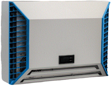
- Model: SCE-NG1870B230V
- Intended Use: Dissipation of heat from control cabinets and enclosures
- Voltage: 230V
User Manual
This instruction manual contains information and instructions to enable the user to work safely, correctly and economically on the unit. Understanding and adhering to the manual can help one:
- Avoid any dangers
- Reduce repair costs and stoppages
- Extend and improve the reliability and working life of the unit
PLEASE ENSURE TO USE THE RIGHT VERSION OF THE INSTRUCTION MANUAL SUITABLE FOR YOUR UNIT
Intended use
The unit is to be used exclusively for the dissipation of heat from control cabinets and enclosures in order to protect temperature sensitive components in an industrial environment. To meet the conditions of use, all the information and instructions in the instruction manual must be adhered to.
 General Danger
Indicates compulsory safety regulations which are not covered by a specific pictogram such as one of the following. High Electric Voltage
Indicates electric shock danger. Important Safety Instruction
Indicates instructions for safe maintenance and operation of the unit. Attention
Indicates possible burns from hot components. Attention
Indicates possible damage to the unit. Instruction
Indicates possible danger to the environment.
Legal Regulations
Liability
The information, data and instructions contained in this instruction manual are current at the time of going to press. We reserve the right to make technical changes to the unit in the course of its development. Therefore, no claims can be accepted for previously delivered units based on the information, diagrams or descriptions contained in this manual. No liability can be accepted for damage and production caused by:
- Disregarding the instruction manual
- Operation error
- Inappropriate work on or with the unit
- The use of non-specified spare parts and accessories
- Unauthorized modifications or changes to the unit by the user or his personnel
Saginaw Control & Engineering is only liable for errors and omissions as outlined in the guarantee conditions contained in the main contractual agreement. Claims for damages on any grounds are excluded.
Safety Instructions
- Upon delivery the unit is already meeting current technical standards therefore it can be safely taken into operation. Only trained specialists are allowed to work on the unit. Unauthorized personnel must be prohibited from working on the unit. Operating personnel must inform their superiors immediately if any malfunction of the unit becomes apparent.
- Please note that before starting to work on or with the unit, a procedure must be carried out inside the cabinet on which the unit is to be mounted.
Before commencing work inside the cabinet, the control cabinet manufacturer’s instruction must be read with regards to:
- Safety instructions
- Instructions on taking the cabinet out of operation
- Instructions on the prevention of unauthorized cabinet reconnection
The electric equipment meets the valid safety regulations. One can find dangerous voltage (above 50V AC or above 100V DC):
- Behind the control cabinet doors
- On the power supply in the unit housing
The units have to be fused according to the type plate and the wiring diagram. Switch the unit off immediately if the electric power supply is interrupted.
- Danger Through Incorrect Work on the Unit
Only specialized personnel are allowed to maintain and clean the unit. Regular maintenance and cleaning must be kept in order to ensure that the unit remains in perfect working condition and has a long working life. - Danger from Electric Voltage
Only specialized personnel are allowed to maintain and clean the unit. The personnel must ensure that for the duration of the maintenance and cleaning, the unit is disconnected from the electrical supply. - Attention
Damage to the unit through the use of inappropriate cleaning materials. Please do not use aggressive cleaning material. - Instruction
Damage to the environment through unauthorized disposal. All spare parts and associated material must be disposed of according to the environmental laws.
Controllers Used
There are variations of controllers with this unit. The options are as followed variation A, IR33+ controller, and variation B, DISP-1503 controller. Please find the controller on your unit and proceed to the corresponding section.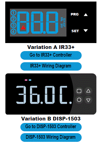
IR33+ Controller Programming
- The cooling unit is intended to be used as a complementary accessory to larger industrial equipment. The unit is used where heat needs to be dissipated from electrical control cabinets or similar enclosures in order to protect heat sensitive components. It is not intended for household use. The unit has two completely separate air circuits which ensure that the clean cabinet air does not come into contact with the ambient air which may well be dirty or polluted. Enclosure cooling units can dissipate large quantities of heat from sealed enclosures such as electrical enclosures into the ambient air and at the same time reduce the cabinet internal temperature to below that of the ambient air.
- The unit can function without problems in extreme ambient conditions (e.g. dusty and oily air) with a standard operating temperature ranging between +10°C and +55°C. Units can be ordered with an additional electrical cabinet heater. For the cooling capacities and environmental ratings please refer to the type plate data.
Controller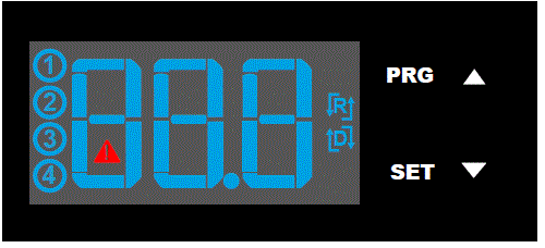
- The display shows the temperature in the range of -50°C to +150°C (-58°F to +302°F). The temperature is displayed with resolution of tenths between -19.9° and +99.9°.
- During programming, it shows the codes and values of the parameters. The display also shows icons according to occurring events.
Display icons Icon Function Description
- Compressor relay active Flashes when activation is delayed or inhibited by protection times, external disabling, or other procedures in progress
- Alarm relay active
- Heater relay active
- Ambient blower relay active
 Alarm Flashes when alarms are active
 Heating mode Signals operation of unit in heating mode
 Cooling mode in progress Activated only by manual procedure
Programming
The operating parameters can be modified using the front keypad. Access differs depending on the type of parameter. Access to configuration parameters is protected by a password that prevents unwanted modifications or access by unauthorized persons.
Setting cooling set point, St1: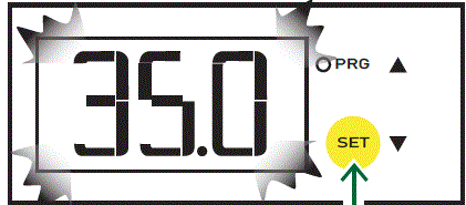
- Press and hold “SET” until the display shows St1. Once released the pre-set value of St1 will appear.(default: +35°C / +95°F)
- Reach the desired value by using ▲ or ▼.
- Press “SET” again to save the new value of St1.
Setting heating set point, St2 (only for units supplied with internal heater):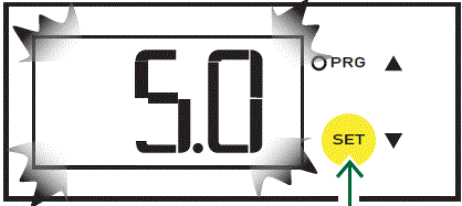
- Press “SET” twice slowly and display should show St2 and then the pre-set value of St2. (default:+5°C / +41°F)
- Reach the desired value by using ▲ or ▼.
- Press “SET” again to save the new value of St2.
Setting temperature units (°C / °F), low temperature alarm and high temperature alarm: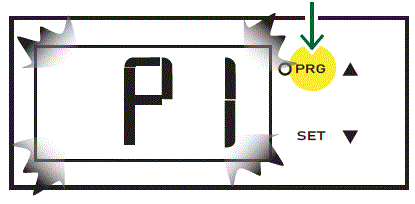
- Press “PRG” button for 5 seconds to reach the modifiable parameter list.
- Use ▲ or ▼ to reach the desired parameter:
- C18 for temperature unit of measure
- °C = 0
- °F = 1
- P25 for low temperature alarm threshold (default -10°C / +14°F)
- P26 for high temperature alarm threshold (default +55°C / +131°F)
- Press “SET” on the desired parameter to display the current value.
- Use ▲ or ▼ to reach the desired value.
- Pressing “SET” temporarily saves the new value and returns to the parameters list.
- Repeat steps 2-5 to set other parameters.
- Press “PRG” for 5 seconds to permanently save the new values.
Test Function
Different test functions can be used depending on the combination of keys pressed. Such tests run for the duration of 4 minutes.
- “SET+▲” tests Compressor and Ambient Blower relays.
- “SET+▼” tests Alarms and Heater relays
Alarm Relay Function
Both normally closed (NC) and normally open (NO) alarm contacts are provided. These refer to the alarm state. Under normal conditions, the NC contact is closed and the NO contact is open. When an alarm condition is present or the door contact is open, the NC contact will open and the NO contact will close. System power failure will give an alarm condition.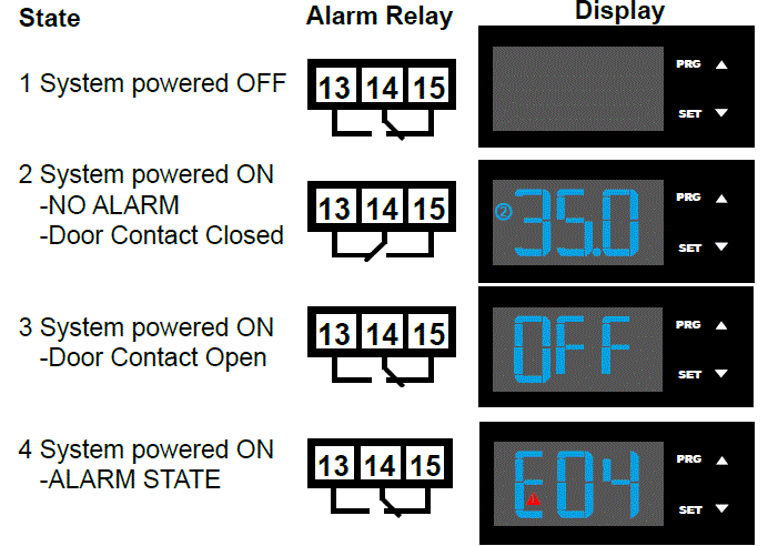
Notes:
- State 2: Additional icons (1,3,4, Reverse, Direct, Test) depending on operation.
- State 3: The display shows “OFF” alternating with the standard display.
- State 4: The display shows “EXX” alternating with the standard display – at the same time, the alarm icon flashes.
Failure table:
The display shows either ‘’OFF’’ or “EXX” with an icon flashing (triangle), alternating with the standard display. If more than one error occurs, these are shown in sequence on the display.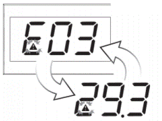
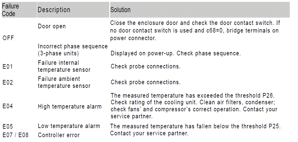
Typical alarm codes:
Error Code Description
- E01 Probe B1 fault
- E02 Probe B2 fault
- E04 High temperature alarm
- E05 Low temperature alarm
Important Notes
- Whilst programming, if no button is pressed for 10 seconds, the display starts flashing, and after 1 minute returns to the main display without saving changes.
- To increase scrolling speed, press and hold the ▲ or ▼ button for at least 5 seconds.
- When pressing “PRG” for 3 seconds, the firmware revision code is displayed for 2 seconds.
- When cleaning the controller panel, do not use ethanol, hydrocarbons, ammonia or their by products. Use neutral detergents and water.
- In order to protect the unit’s components, minimum relay output on (3 or 7 minutes) and off (4 minutes) times and minimum time (7 or 11 minutes) between activation of the same relay output are applied.
- In case of digital inputs not configured, probes not fitted or configured, or St2 not enabled on the controller the display shows ‘nO’.
DISP-1503 Controller Programming
- The cooling unit is intended to be used as a complementary accessory to larger industrial equipment. The unit is used where heat needs to be dissipated from electrical control cabinets or similar enclosures in order to protect heat sensitive components. It is not intended for household use.
- The unit has two completely separate air circuits which ensure that the clean cabinet air does not come into contact with the ambient air which may well be dirty or polluted. Enclosure cooling units can dissipate large quantities of heat from sealed enclosures such as electrical enclosures into the ambient air and at the same time reduce the cabinet internal temperature to below that of the ambient air.
- The unit can function without problems in extreme ambient conditions (e.g. dusty and oily air) with a standard operating temperature ranging between +10°C and +55°C (+50°F and +131°F). Units can be ordered with an additional electrical cabinet heater. For the cooling capacities and environmental ratings please refer to the type plate data.
Controller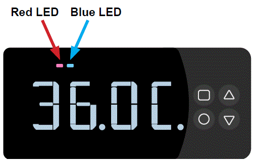
Buttons LED Functions
 Menu Blue LED: Steady On – Cooling mode
 Blue LED: Blinking – min. comp. off time not elapsed
 Red LED: Blinking – Alarm
 Down
Down
The display shows the temperature in the range of -30°C to +110°C (-22°F and +230°F). The temperature is displayed with a resolution of 0.1° between -9.9° and +110°, and 1° between -30° and -10°. On start-up, the screen shows the unit’s internal temperature and this is considered the Home Menu of the controller.
Programming Quick Reference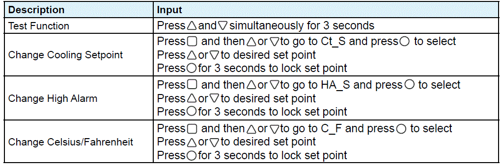
Operations from Home Screen
- Pressing or for 1 second will go to Menu 1. This will show the status of DI1, DI2, S1, S2 and Onboard Sensor. Pressing or will toggle between sensors/digital inputs.
- Pressing will go to Menu 2.
- Any Alarms will appear on the Home Screen.
- If the Door Contact is Open, the Home Screen will show an OFF status.
- Pressing and simultaneously for 3 seconds will start Test Mode.
Operations from inside the Menus
- Pressing from any menu will return to the Home Screen.
- Pressing while in Menus 2/2 shows the parameter value.
- Pressing for 3 seconds while showing a parameter, will save the parameter.
- Pressing while showing a parameter, will return to the respective menu. All parameters are sorted in 2 separate menus below
Menu 1
| Parameter | Description | Range |
| Sbrd | Onboard Sensor Reading | – |
| S1 | S1 Sensor Reading | – |
| S2 | S2 Sensor Reading | – |
| d1 | Digital Input 1 Reading |
|
| d2 | Digital Input 2 Reading |
|
Menu 2
| Parameter | Description | Input | Setting range |
| Ct_S | Control Setpoint |
|
|
| HA_S | High Alarm Setpoint |
|
|
| LA_S | Low Alarm Setpoint |
|
|
| Ht_S | Heater Setpoint |
|
|
| C_F | Celsius / Fahrenheit |
|
|
| IP_1 | Input 1 Invert |
|
|
| StAt | System State | Read Only |
|
| OUtP | Relay Outputs | Read Only |
|
Alarm codes
| Alarm Code | Description |
| AL1 – HI | High Temp Alarm |
| AL2 – LO | Low Temp Alarm |
| AL3 – PrEP | Pressure Pipe Alarm |
| AL4 – AbS | Ambient Sensor Faulty |
| AL5 – PPS | Pressure Pipe Sensor Faulty |
| AL6 – ICES | Ice Sensor Faulty |
| AL7 – InS | Internal Sensor Faulty |
| NA | Not Available |
| AL9 | …Check ‘Digital Input 2’ Table below |
| AL10 – ICE | Ice Algorithm Active |
| AL11 – SLOC I | Incorrect Sensor Location |
Digital Input 2 Table
| dIn2 | Generic Error |
| PH_F | Phase Failure |
| Pr_S | Pressure Switch |
| FL_S | Float Switch |
Digital Input 2 Table
- Test mode is started by simultaneously pressing and for 3 seconds from the Home screen.
- When Test run is active, tESt will be shown blinking on the display
Test procedure when Internal Temperature is between 10°C and 50°C C (50°F and 122°F)
| 0 to 30 seconds | Ambient Blower |
| 30 seconds to 5:30 Minutes | Ambient Blower + Compressor |
| 5:30 Minutes to 6:30 Minutes | Ambient Blower + Heater |
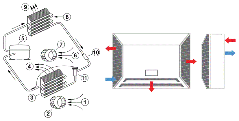
Functional Principle
- The cooling unit for enclosures works on the basis of a refrigeration circuit consisting of four main components: compressor, evaporator, condenser and expansion device.
- The circuit is hermetically sealed and R134a refrigerant circulates inside it (R134a is chlorine free and has an Ozone Destruction Potential [ODP] of 0 and a Global Warming Potential [GWP] of 1430).
- The compressor compresses the refrigerant (thus taking it to high pressure and high temperature), and pushes it through the condenser, where it is cooled by ambient air thus passing from the gas to the liquid state. At the liquid state it then passes through the capillary pipe being a much lower pressure the refrigerant arrives to the evaporator where it absorbs the necessary heat to change from liquid to gas state. The gas is then drawn back into the compressor completing the cycle.
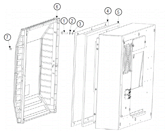
- Air Intake, Cabinet Side
- Radial Fan, Cabinet Side
- Evaporator
- Air Outlet, Cabinet Side
- Compressor
- Air Intake, Ambient Side
- Radial Fan, Ambient Side
- Condenser
- Air Outlet, Ambient Side
- Filter Dryer
- Expansion Valve
Technical Data
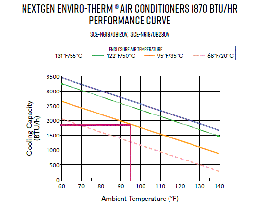
- Part Number SCE-NG1870B230V
- Cooling Capacity @ 95°F / 95°F 1880 BTU
- Cooling Capacity @ 95°F / 131°F 410 W @ 50 Hz 440 W @ 60 Hz
- Compressor Rotary piston
- Refrigerant / GWP R134a / 1430
- Refrigerant Charge 98 g / 3.46 oz
- High / Low Pressure 363 / 87 psi
- Operating Temperature Range 50°F – 140°F
- Air Volume Flow (System / Unimpeded) Ambient Air Circuit: 200 / 408 m³/h
- Cabinet Air Circuit: 122 / 180 m³/h
- Mounting Wall Mounted / Recessed
- Housing Material Mild Steel, Powder Coated
- Dimensions (H x W x D) 14.6 x 20.5 x 6.2 inch
- Weight 35.3 lbs
- Rated Operating Voltage / Frequency 230 V ~ 50/60 Hz
- Rated Current @ 95°F / 95°F 1.8 A @ 50 Hz 1.8 A @ 60 Hz
- Starting Current 6 A
- Max. Current 2.5 A
- Nominal Power 95°F / 95°F 355 W @ 50 Hz 380 W @ 60Hz
- Max. Power 560 W
- Fuse Rating 15 A (T)
- Circuit Breaker MCB Type D or K 15A [Slow Acting]
- Connection
- 5 pole terminal for signals
- 4 pole terminal for power
- 3 pole terminal block for RS 485 Modbus
- NEMA Protection Class Type 3, 3R, 12, 4
- Approvals CE, cURus, cULus
Short Circuit Current Rating for Air Conditioners and Heat Exchangers
- As per UL508A Supplement SB, Seifert Systems’ air conditioners have a default SCCR of 5 kA.
- If no additional measures are taken in the installation, the resulting SCCR rating in the control panel would be 5 kA, assuming that the air conditioner is the lowest rated component in the panel.
However, a high fault SCCR is conditional on the use of specific over current protective devices. - Table SB4.2 (UL508A) lists the Fuse Peak let through currents, Ip, and clearing, I2t, based on available short circuit current levels for a number of fuse types. A high fault SCCR can be achieved with the use of a time delay fuses such as Class CC. The current limiting fuse used must have a SCCR higher or equal than that of the panel. Additionally, the let through current Ip of the fuse must be less than 5 kA. The fuses must be marked as Current Limiting and the let through current must be verified from the manufacturer’s curves. Refer to the unit’s type plate data for fuse rating
- Article 409 of the 2008 National Electric Code (NFPA 70) requires industrial control panels to be marked with a short circuit current rating. As specified in the National Electric Code, UL508A-2001
- Supplement SB, the Standard of Safety for Industrial Control Equipment, provides an accepted method for determining the short-circuit current rating of the control panel.
- The SCCR rating for our air conditioners and heat exchangers has a default value of 5 kA.
- You may use a 5 or 10 kVA isolation transformer between the customer’s panel and our air conditioner and not have an effect on the customer’s 65kA rating. You may use a fuse or circuit breaker with a 5 kA short circuit rating on the line side of the ACU and its branch circuit protective device and not have an effect on the customer’s 65 kA rating.
- The current limiting fuse or circuit breaker used on the line side of the branch circuit protection for the ACU must have a SCCR => that of the panel rating. Additionally for a current limiting fuse the customer would need to verify using table SB4.2 of UL 508A, that the let through current (Ip * 103)of the fuse is <= 5KA. If a circuit breaker is used as feeder protection, it must be marked Current Limiting type from the manufacturer, and the panel builder would need to verify based on the manufacturers published curves that it will let through <= 5kA. Examples of these curves are included in UL 508A supplement SB.
- You can run separate circuits for the panel and the air conditioner as long as each is labeled with their individual SCCR ratings. (5 kA and 65 kA) If the customer does not implement one of the options above, then the resulting SCCR rating would be the 5 kA rating of the ACU, if that is the lowest rated component in the panel.
- Testing represents another option; however, if the customer does not implement these options, then the resulting short circuit rating of the panel is based on the lowest short circuit current rating of all power circuit components installed in the panel.
Mounting
- The power supply rating on unit rating plate must comply with mains rating.
- Always disconnect the power supply before opening the unit.
- Heat load to be dissipated from enclosure should not exceed specific cooling output of the unit at any condition. When selecting a cooling unit, always allow for a safety margin of at least 15% extra cooling output in the worst conditions.
- Air inlets and outlets must be completely free from obstruction. Ensure that flows of air leaving and entering the cooling unit, internal and external, are not obstructed. It must also be ensured in accordance with UL, that the air outlet is not blowing air directly at an equipment operator. Should this be the case a barrier or duct shall be provided to redirect the airflow.
- Cooling unit enclosure air suction hole must be installed at the highest possible point. When installing the unit on a door ensure it can take the weight.
- Before drilling the enclosure, ensure the fixing elements and couplings will not interfere with the equipment inside the enclosure itself. Disconnect power before starting any work inside the enclosure.
- Following the Drilling Template, drill the holes and make the required cuts on the enclosure. This template may have been affected by storage conditions, please check this template by verifying values of the largest dimensions before drilling. Fit the sealing strip to the cooling unit on the side connected to the enclosure and follow the installation diagram.
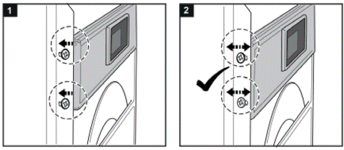
- If the unit is mounted in a recessed position, the controller bracket can be pulled according to the wall thickness of the enclosure outwards as per steps below.
Condensate Management
High humidity and low temperatures inside the enclosure can lead to condensation on the evaporator. Condensate that flows back into the enclosure can damage sensitive control electronics. The integrated condensate evaporation of the cooling unit releases the condensate to the environment. If condensate formation is too great, additional condensate can drip into an overflow trough, which then drains off on the ambient side. In order to prevent the formation of excessive condensate, you should nevertheless:
- Check the seals at regular intervals
- Consider installing a door contact switch. This can prevent condensation forming when enclosure door is left open.
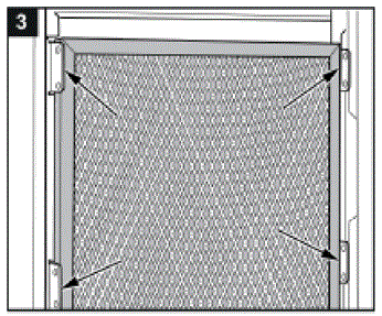
Filter installation
If you install / replace a filter please follow the steps below.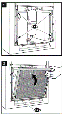
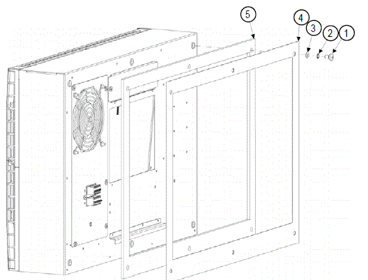
Mounting Principle
- Do not use within the first 15 minutes after installation!
- Use only the supplied mounting hardware.
- Tighten Screws to 4.5 Nm.
- Ensure the mounting surface does not warp after assembly and reinforce it if necessary.
- M6 screws
- M6 toothed washers
- M6 flat washers
- Enclosure
- Mounting gasket
- Lifting hook
- Cover
- M4 screws
Fig. 1 Recessed
Fig. 2 External
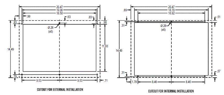
Cutout Dimensions
Dimensions (H x W x D)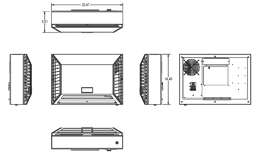
Electrical Connection
Caution, risk of death
- Unconnected and / or faulty protective conductor systems can lead to dangerous voltages and electric shocks which can cause serious accidents.
- Work on electrical connections may only be carried out by trained electrical engineers.
Alarm Contacts
Alarm contacts ratings:
- Maximum switching power 60 W / 125 VA, maximum switching voltage 220 VDC / 250 VAC, maximum switching current 2 A, maximum carrying current 2 A.
- These contacts are not suitable for fluorescent loads (neon lights, etc.) that use starters (ballasts) with phase shifting capacitors. Fluorescent lamps with electronic controllers or without phase shifting capacitors can be used, depending on the operating limits specified for each type of relay.
Strain relief function
In order to maintain the UL listing approval, the supplied strain relief bracket and cable glands must be installed.
IR33+ Wiring Diagram
Part List
- Sa: Ambient Temperature Sensor (Optional)
- Si: Internal Temperature Sensor
- Hcc: Compressor c/case heater (Optional)
- Hce: Condensate evaporator heater
- Hi: Internal heater
- Cc: Compressor capacitor
- Ps: DC Power Supply
- Mc: Compressor
- Ma: Ambient fan
- Mi: Internal fan
Notes
- See unit type plate for correct operating voltage and frequency. Suitable protective devices should be installed on the supply line. Use copper conductors only.
- Use supply wires suitable for (167°F).
- Connected for units with internal heater. (Optional)
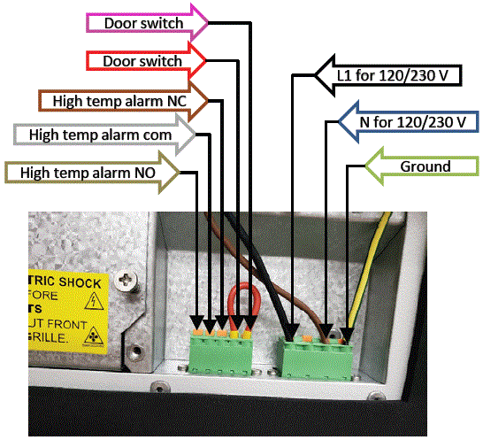
| Power Connector | 1 | L |
| 2 | – | |
| 3 | N | |
| 4 | PE | |
| Alarms/signals connector | 1 | Normally closed alarm contact |
| 2 | Alarm contact (COM) | |
| 3 | Normally open alarm contact | |
| 4 | Door contact | |
| 5 | Door contact | |
| RS485 connector | 1 | A |
| 2 | Gnd | |
| 3 | B |
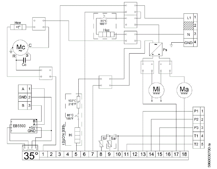
Notes
High temp alarm can be wired NC or NO
- When wires: P1 P2 – NC
- When wires: P2 P3 – NO
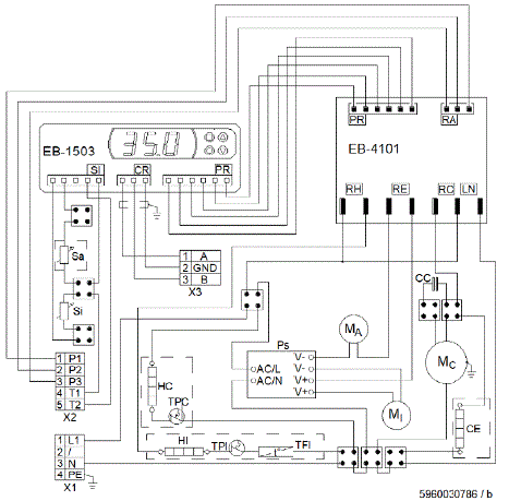
DISP-1503 Wiring Diagram
Part List
- X1: Power connector
- X2: Signals/alarms connector
- X3: Master/slave connector
- Mi: Internal fan
- Ma: Ambient fan
- Mc: Compressor
- Cc: Compressor capacitor
- Si: Internal temperature sensor
- Sa: Ambient temperature sensor
- Hi: Internal heater
- Hc: Compressor crankcase heater
- Ps: 12VDC power supply
- Ce: Condensate Evaporator
Notes
- Use supply wires suitable for (167°F).
- Use copper conductors only.
- Optional components in dashed borders.
Modbus Connection
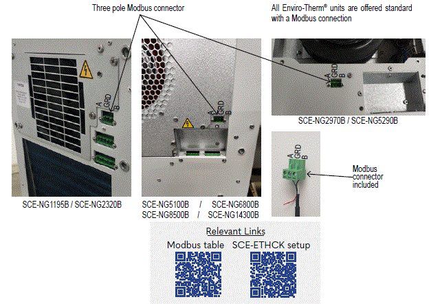
Detailed instructions on Modbus communication can be found in the link below https://www.saginawcontrol.com/instman/modbus-table.pdf
Further notes:
- From Modbus side, any setting can be with 0.1°C precision. From the display, the precision is 0.5°C. When having a setting, example 30.4°C, this will be rounded to 30.5°C when accessed via display.
- When system detects incorrect sensor mapping, it sends unit into idle and triggers an alarm on display. No alarm is shown on Modbus.
- When Ambient, Icing and Pressure are not enabled, the value displayed (Modbus/Seifert Software) is -50°C.
- When saving settings via communication, S is shown on display for 1 second.
- When system goes in Cooling Mode, C is shown on display for 1 second.
- When system goes in Heating Mode, H is shown on display for 1 second.
- When accessing the Display Settings of Menu 2/3/4, any settings from Modbus are ignored.
- When running a test with the door contact open, the display only shows TEST, since the unit will not be OFF.
- When running a test with Alarms, the Alarms and TEST are shown together.
- On Start-up, the communication is by default Modbus. It can be changed to Seifert Protocol by writing a code in register SET_CHANGE_PROTOCOL. After 10 seconds of no communication, system changed back to Modbus.
- When unit is not Modbus Address 1, the Master/Slave and Redundancy parameters are hidden from Menu3 when using Client Password. (MS1, MS2, MdL, rS1, rS2, rS3).
- Enabling the Pressure sensor from Modbus can only be done if the unit is not in cooling mode.
- The Blue LED is ON when the unit is cooling.
- A red LED is ON when the unit is heating.
- The red LED flashes when an alarm is present
Taking Into Operation
Attention!
- The unit can be damaged by lack of lubricant. To ensure that the compressor is adequately lubricated, the oil, which has been displaced during transport, must first be allowed to flow back into place.
- The unit must therefore be allowed to stand for at least 30 min. before being connected to the mains and taken into operation.
- The unit / system must be protected with a MCB Type D or K. Upon connection the internal fan will start working. If the temperature inside the enclosure is higher than the set value of the controller both the compressor and external air fan start working. The cooling cycle will either stop once the air inside the enclosure reaches the set temperature minus hysteresis or once the minimum On-time is reached.
- The hysteresis is 3K, the minimum ON-time is 4 minutes, the minimum OFF-time is 3 minutes, for units with a cooling capacity of more than 1 kW is it usually 7 minutes.
- The setpoint for the internal enclosure temperature is pre-set at 95°F.
Maintenance & Cleaning
Always switch power supply off before starting any maintenance on the unit. Wait for 5 minutes for electrical components to discharge.
- The cooling unit is generally maintenance free and can be operated without filters in most environments.
- If the ambient air is extremely dusty, we recommend installing filter mats (see accessories). These should be cleaned or replaced at regular intervals. Oily or greasy filter mats should be replaced immediately. Do not use a steam jet or high pressure to clean the filter mats. Do not wring out the filter mats. If the ambient air is extremely oily, we recommend the use of metal filters (see accessories).
- They can be cleaned with standard cleaning agents and reused. In addition the unit should have regular functional tests (approx every 2,000 hours depending on the grade of ambient pollution).
Note: The use of filter mats / metal filters reduces the cooling capacity of the unit.
Disposal
The cooling unit contains R134a refrigerant and small quantities of lubricating oil. Replacement, repairs and final disposal must be done according to the regulations of each country for these substances.
Transportation & Storage
Malfunction due to transport damage
On delivery the carton box containing the unit must be examined for signs of transport damage. Any transport damage to the carton box could indicate that the unit itself has been damaged in transit which in the worst case could mean that the unit will not function.
The unit can only be stored in locations which meet the following conditions:
- Temperature range: -40°F to 158°F
- Relative humidity (at 77°F): max. 95%
- The cooling unit should always be stored according to the installation position
Returning the unit
To avoid transport damage the unit should be returned in the original packing or in a packing case and must be strapped to a pallet. If the unit cannot be returned in the original packing please ensure that:
- A space of at least 30 mm must be maintained at all points between the unit and the external packing
- The unit must be shipped in the same position as it was mounted
- The unit must be protected by shock resistant padding (hard foam corner pieces, strips or cardboard corner pieces)
Parts Supplied
Parts Supplied
- Full version of instruction manual
- CE declaration of conformity
- 1:1 mounting template
- M6 * 16 bolts x 6
- A6.4 toothed washers x 6
- A6.4 washers x 6
- 5 – pole terminal block for signals x 1
- 4 – pole terminal block for electrical connection x 1
- 3 – pole terminal block for RS 485 MODBUS x 1
- Drain fitting x 1
- Foam tape
Troubleshooting
| Failure | Condition | Cause | Solution |
| Unit Does Not Cool | Internal fan does not work | Power not connected | Verify power supply |
| Internal fan works, external fan and compressor do not work | Enclosure temperature is below setting temperature (St) | Verify values of parameter “St” | |
| Door switch contact is open | Verify door switch | ||
| Controller does not work | Replace controller | ||
| Internal fan works, external fan and compressor do network Display shows alternating “OFF” and temperature | The sequence of the phases inside the power supply connector is incorrect | Change phases inside power supply connector | |
| External and internal fan work, compressor does not work | Compressor motor electrical failure | Verify external fan, verify ambient temperature, clean condenser | |
| Capacitor for compressor failed | Replace capacitor | ||
| Compressor works, external fan does not work | External fan needs to be replaced | Replace external fan | |
| Enclosure Overheating | Compressor and fans (external and internal) work all the time | Unit cooling undersized | Enclosure needs a bigger cooling unit |
| Compressor and external fan work in alternating mode (ON / OFF) | Thermal compressor protector triggered | Verify ambient temperature, clean condenser | |
| Refrigerant leakage | Contact dealer/service center | ||
| Excessive Condensate | Door enclosure open | Ambient air gets into the enclosure | Ensure door is closed, add a door switch and connect it to controller |
| Door enclosure closed | Enclosure IP degree minimumIP54 | Seal openings on enclosure | |
| Damaged/misplaced sealing strip | Repair strip accordingly |
Warranty / Limits of Liability
- All goods manufactured by SCE shall be warranted to be free of defects in material or workmanship for a period of two years from the date of shipment. Should the product be proven to SCE to be defective, we shall option to repair or replace the product. At no time will SCE reimburse purchaser for unauthorized rework on any product.
Air Conditioners & Heat Exchangers are warranted on parts and service for a period of two years from the date of shipment by Saginaw Control and subject to the following conditions and exclusions: - All Goods must be installed and operated according to the following specifications: Maximum voltage variation no greater than plus or minus 10% of nominal rating; Maximum frequency variation no greater than plus or minus 3 Hz. from nominal rating; Must not exceed minimum and maximum rated temperatures; Must not exceed (BTU/Hr) rating; Filters must be cleaned regularly; Must be installed and grounded in accordance with all relevant electrical and safety codes, as well as the National Electric Code and OSHA rules and regulations; Must be installed in a stationery application, free of vibration.
- Our warranty does not warranty product that has been modified, subjected to abuse, negligence in operation or maintenance, or if product is used in a manner that exceeds its designed capabilities and rating.
- Warranty related claims will be returned to the factory for evaluation and final disposition of the claim, any replacement parts will be invoiced at standard pricing and credit issued for the returned product. If the product has been found to have been modified, subjected to abuse, negligence in operation or maintenance, or if product has been used in a manner that exceeds its designed capabilities and rating, credit may be reduced, denied or additional cost may be assessed and passed on to the purchaser, such as return freight.
Saginaw Control and Engineering
- 95 Midland Road
- Saginaw, MI 48638-5770
- Phone: 989-799-6871
- Fax: 989-799-4524
- sce@saginawcontrol.com
FAQ
- Q: Who is allowed to work on the unit?
- A: Only trained specialists are permitted to work on the unit. Unauthorized personnel must not handle the unit.
- Q: What precautions should be taken before starting work on the unit?
- A: Before commencing work, ensure that the control cabinet manufacturer’s instructions are read thoroughly, and all safety regulations are met. Additionally, make sure the unit is disconnected from the power supply if maintenance or cleaning is required.
Documents / Resources
 |
SCE DISP-150 Controller Video [pdf] User Manual IR33, DISP-1503, DISP-150 Controller Video, Controller Video, Video |