SandC CS-1A Type Switch Operators
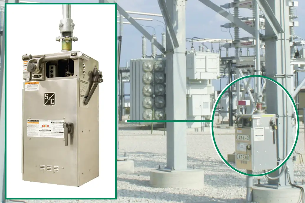
High-speed Type CS-1A Switch Operators are expressly designed for power operation of S&C Mark V Circuit-Switchers.
Introduction
Type CS-1A Switch Operators provide the highspeed, high-torque power operation required to secure the full inherent mechanical and electrical performance characteristics of Mark V Circuit- Switchers, including close interphase simultaneity, long life of fault-closing contacts under normal operating duties, and avoidance of excessive switching transients caused by prolonged or unstable prestrike arcing.
For vertical‑break and integer-style Mark V Circuit‑Switchers, Type CS-1A Switch Operators also provide two‑time duty‑cycle fault‑closing ratings of 30,000 amperes RMS three-phase symmetrical, 76,500 amperes peak; and opening and closing without hesitation under 3/4-inch (19-mm) ice formation. And for center-break style Mark V Circuit-Switchers, Type CS-1A Switch Operators also provide two-time duty-cycle fault-closing ratings of 40,000 amperes RMS three-phase symmetrical, 102,000 amperes peak, and opening and closing without hesitation under 1½-inch (38-mm) ice formation.
Figure 1 on page 2 shows some of the important features discussed in detail in the “Construction and Operation” section on page 2.
S&C TYPE CS-1A SWITCH OPERATORS
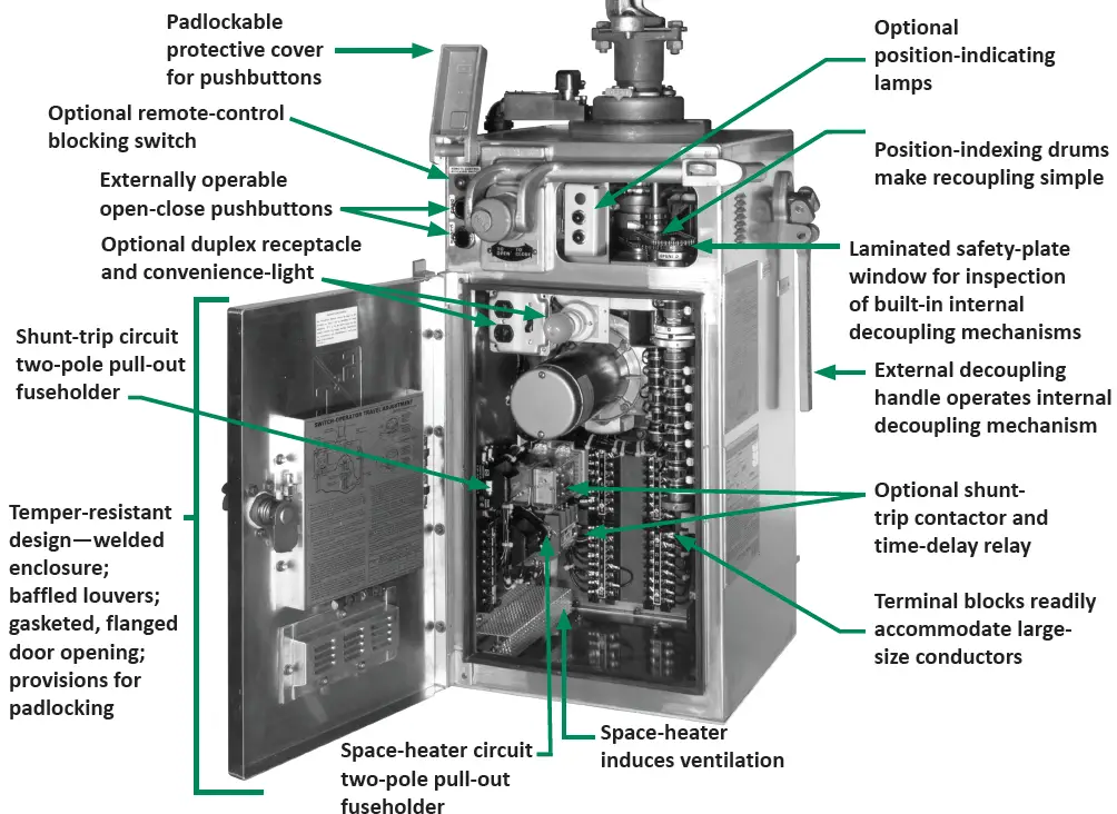
Construction and Operation
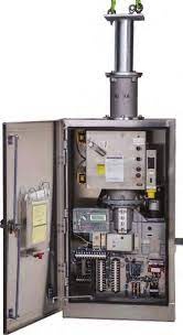
The Enclosure
The switch operator is housed in a weatherproof, dust-proof enclosure of sturdy, 3/32-inch (2.4‑mm) sheet aluminum. All seams are welded, and enclosure openings are sealed with gasketing or O-rings at all possible water-ingress points. A fused space heater is provided to maintain air circulation for condensation control. The space heater is factory-connected for 240-Vac operation but can be readily field-reconnected for 120-Vac operation. Access to the interior components is by door rather than by removal of the entire enclosure, an obvious advantage during foul weather.
To ensure the utmost security against unauthorized entry, the enclosure includes such features as:
- A cam-action latch, which seals the door in compression against gasket
- Two concealed hinges
- A laminated safety-plate glass, gasket-mounted observation window
- A padlockable door handle, pushbutton protective cover, manual operating handle, and decoupling handle
- A key interlock (when specified)
Power Train
The power train consists essentially of a reversible motor coupled to the output shaft at the top of the operator. Motor direction is controlled by a supervisory switch that actuates the opening or closing contactor as appropriate to energize the motor and to release the electromagnetic brake. Fingertip precision adjustment of output-shaft rotation is provided by means of self-locking spring-biased cams. Anti-friction bearings are used throughout; the gear-train shafts feature tapered roller bearings.
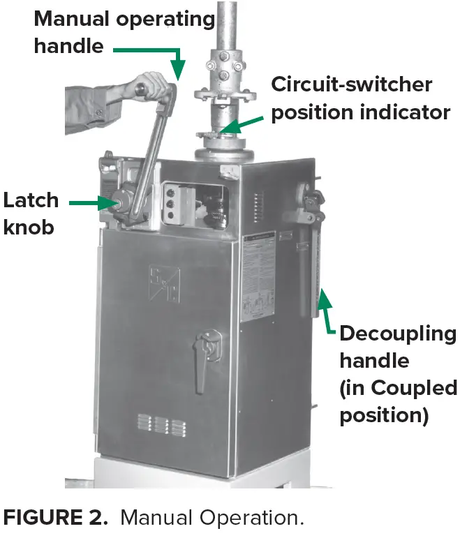
Manual Operation
A built-in nonremovable, foldaway manual operating handle for manually opening and closing the circuit-switcher is located on the front of the switch‑operator enclosure. See Figure 2. By pulling the latch knob on the hub of the manual operating handle, the handle can be pivoted from its Storage position to the Cranking position.
As the handle is pivoted forward, the motor brake is mechanically released, both leads of the power source are automatically disconnected, and both the opening and closing motor contactors are mechanically blocked in the Open position. However, the circuit‑switcher shunt-trip device (if furnished) remains operative.
If desired, the switch operator may also be disconnected from the control during manual operation.
Externally Operable Internal Decoupling Mechanism
An integral external selector handle for operating the built-in internal decoupling mechanism is located on the right-hand side of the switchoperator enclosure. See Figure 2 on page 3.
By swinging this handle upright and rotating it clockwise 50º, the switch-operator mechanism is decoupled from the output shaft. When thus decoupled, the switch operator may be manually or electrically operated without operating the circuitswitcher, and the shunt-trip device (if furnished) is rendered inoperative. 1 When decoupled, the switchoperator output shaft is prevented from moving by a mechanical locking device within the operator enclosure.
During the intermediate segment of the disconnect handle travel, which includes the position at which actual disengagement (or engagement) of the internal decoupling mechanism occurs, the motorcircuit source leads are momentarily disconnected, and both the opening and closing motor contactors are mechanically blocked in the Open position. Visual inspection through the observation window helps verify whether the internal decoupling mechanism is in the Coupled or Decoupled position. See Figure 3. The disconnect handle may be padlocked in either position.
Recoupling is simple. It is impossible to couple an “open” circuit-switcher with the switch operator in the Closed position, or vice-versa. Coupling is possible only when the switch-operator output shaft is mechanically synchronized with the switchoperator mechanism. This synchronization is readily achieved by manually or electronically operating the switch operator to bring it to the same Open or Closed position as the circuit-switcher. The switch-operator position indicators, viewed through the observation window, show when the approximate Open or Closed position has been attained. See Figure 3. Then, to move the switch operator to the exact position for coupling, the manual operating handle is turned until the positionindexing drums are numerically aligned.

- Only the shunt-trip device is rendered inoperative. The switch operator can still be opened through the user’s protectiverelay circuit. Thus “elective” checkout of the system protective scheme is possible at any time.
Travel-Limit Switch Adjustment
A travel-limit switch coupled to the motor governs the extent of output-shaft rotation in the opening and closing directions. It includes six contacts operated by cam-actuated rollers. Positioning of the cams to properly engage the rollers is accomplished by means of two travel-limit discs, one for the opening stroke and one for the closing stroke.
Each travel-limit disc is precisely adjusted by means of a self-locking spring-biased cam. Opening travel is adjusted by raising and turning the openingstroke travel-limit disc to the required position on the indicator plate while holding the handwheel. Similarly, closing travel is adjusted by lowering and turning the closing-stroke travel-limit disc to the required position on the indicator plate while holding the handwheel.
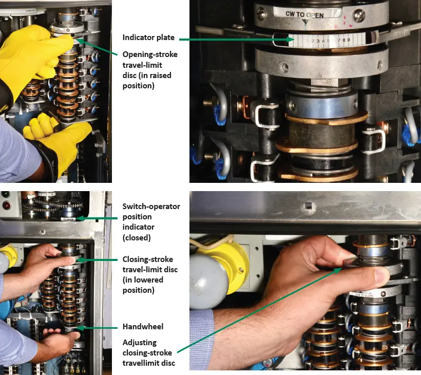
Actuating the opening-stroke travel-limit disc de‑energizes the opening contactor, which then de‑energizes the brake-release solenoid to halt motion of the mechanism. Actuating the closingstroke travel-limit disc de‑energizes the closing contactor, which then also de-energizes the brakerelease solenoid to halt motion of the mechanism.
Auxiliary Switches
An eight-pole auxiliary switch coupled to the motor is furnished as a standard feature. It provides eight individually adjustable contacts pre-wired to terminal blocks (six contacts are available if the switch operator is furnished with optional positionindicating lamps, catalog number suffix “-M”). These contacts are furnished so external circuits can be established to monitor switching operations.
Like the travel-limit discs, each auxiliary switch contact has a self-locking spring-biased cam that permits precise adjustment of cam-roller engagement at the desired point in the operating cycle. Cam position is adjusted by raising (or lowering) the cam toward its adjacent spring and rotating it to the desired position. See Figure 5. An extra four-pole auxiliary switch coupled to the motor and using the same construction is available as an option (catalog number suffix “-Q”)
An extra auxiliary switch coupled to the circuitswitcher is also available as an option and can be provided so the external contacts can be established to monitor circuit-switcher operations. This auxiliary switch also uses self-locking springbiased cams. It can be furnished in an eight-pole version (catalog number suffix “-W”) or in a 12-pole version (catalog number suffix “-Z”).

Provision for S&C Shunt‑Trip Device
S&C Mark V Circuit-Switchers equipped with the optional S&C Shunt-Trip Device provide 8-cycle maximum interrupting time. This high-speed circuit interruption facilitates the application of circuitswitchers at the primary side of transformers for protection of the transformers against internal faults, for multiple-contingency backup protection for overloads and secondary faults, and for protection of the source-side circuits from all kinds of transformer faults.
When the shunt-trip device is energized, a highspeed solenoid encased in a weatherproof housing on each pole-unit base rotates the slender lowinertia insulated shaft 15 degrees. This releases the stored energy within the brain for high-speed opening of the interrupter.
Type CS-1A Switch Operators, furnished with Mark V Circuit-Switchers equipped with the shunt-trip device, can be provided with an optional shunt-trip contactor and time-delay relay (catalog number suffix “-HP”). This optional feature minimizes controlcurrent inrush by energizing the shunt-trip device and switch-operator motor in sequence, thus generally permitting the use of smaller-sized control wire between the user’s protective or control relay and the switch operator.
Sequence Control
Correct operation of Mark V Circuit-Switchers depends on charging and latching the storedenergy source within each brain as the disconnect blades move to the fully Open position. The interrupter target located on the side of each brain housing appears yellow when the interrupter is open. The target appears gray (normal) when the interrupter is closed.
Interrupters should never be open while the blades are in the Closed position. To close the interrupters, the circuit-switcher must be completely opened and then reclosed. For this reason, the switch operator incorporates a control circuit that causes the switch operator to return automatically to the Open position whenever the control-source voltage is restored while the switch operator is at any position between fully open and fully closed.
This action takes place regardless of the direction in which it was operating prior to loss of voltage. This control circuit is a built-in feature to prevent the circuit-switcher from being closed from a partially Open position after the interrupters have tripped open.
- Based on minimum battery and external control wire size requirements specified in S&C Data Bulletin 719-60. Operating time will be less if larger-than-minimum battery size and/or external control wire size is used.
- The Type CS-1A Switch Operator is also suitable for use with equivalent models of Mark II, Mark III, and Mark IV Circuit- Switchers. Consult the nearest S&C Sales Office.
- Catalog number 38858R1-B for applications where the circuit-switcher is used in conjunction with an S&C Automatic Control Device, unless the switch operator is ordered with the optional Shunt-trip contactor and time-delay relay accessory, catalog number suffix “-HP.” In this instance, the catalog number is 3RS46R5-BHP.
- CDR-3183 for catalog number 38846R5-BHP; CDR-3195 for catalog number 3885SR1-B
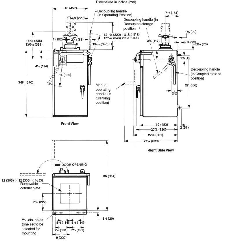
DIMENSION
© S&C Electric Company 2024, all rights reserved
sandc.com
Documents / Resources
 |
SandC CS-1A Type Switch Operators [pdf] Instructions CS-1A Type Switch Operators, CS-1A, Type Switch Operators, Switch Operators, Operators |