Ruijie RG-EST350 V2 Wireless Bridge
Copyright
Copyright © 2024 Ruijie Networks
All rights are reserved in this document and this statement.
Any reproduction, excerption, backup, modification, transmission, translation or commercial use of this document or any portion of this document, in any form or by any means, without the prior written consent of Ruijie Networks is prohibited.
Trademarks including ![]() , are owned by Ruijie Networks.
, are owned by Ruijie Networks.
All other trademarks or registered trademarks mentioned in this document are owned by their respective owners.
Disclaimer
The products, services, or features you purchase are subject to commercial contracts and terms, and some or all of the products, services, or features described in this document may not be available for you to purchase or use. Except for the agreement in the contract, Ruijie Networks makes no explicit or implicit statements or warranties with respect to the content of this document.
The names, links, descriptions, screenshots, and any other information regarding third-party software mentioned in this document are provided for your reference only. Ruijie Networks does not explicitly or implicitly endorse or recommend the use of any third-party software and does not make any assurances or guarantees concerning the applicability, security, or legality of such software. You should choose and use third-party software based on your business requirements and obtain proper authorization. Ruijie Networks assumes no liability for any risks or damages arising from your use of third-party software.
The content of this document will be updated from time to time due to product version upgrades or other reasons, Ruijie Networks reserves the right to modify the content of the document without any notice or prompt.
This manual is designed merely as a user guide. Ruijie Networks has tried its best to ensure the accuracy and reliability of the content when compiling this manual, but it does not guarantee that the content of the manual is completely free of errors or omissions, and all the information in this manual does not constitute any explicit or implicit warranties.
Preface
Intended Audience
This document is intended for:
- Network engineers
- Technical support and servicing engineers
- Network administrators
Technical Support
- Official Website of Ruijie Reyee: https://reyee.ruijie.com
- Technical Support Website: https://reyee.ruijie.com/en-global/support
- Case Portal: https://www.ruijienetworks.com/support/caseportal
- Community: https://community.ruijienetworks.com
- Technical Support Email: service_rj@ruijienetworks.com
- Online Robot/Live Chat: https://reyee.ruijie.com/en-global/rita
Conventions
- Signs
The signs used in this document are described as below:
 Danger
An alert that calls attention to safety operation instructions that if not understood or followed when operating the device can result in physical injury.
 Warning
An alert that calls attention to important rules and information that if not understood or followed can result in data loss or equipment damage.
 Caution
An alert that calls attention to essential information that if not understood or followed can result in function failure or performance degradation.
 Note
Note
An alert that contains additional or supplementary information that if not understood or followed will not lead to serious consequences.
 Specification
An alert that contains a description of product or version support. - Note
This manual provides the device installation steps, hardware troubleshooting, module technical specifications, and specifications and usage guidelines for cables and connectors. It is intended for the users who have some experience in installing and maintaining network hardware. At the same time, it is assumed that the users are already familiar with the related terms and concepts.
Product Overview
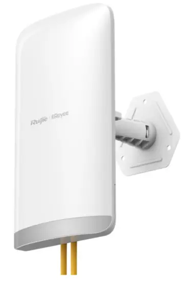
RG-EST350 V2
The RG-EST350 V2 is an 802.11ac wireless bridge launched by Ruijie Reyee. It provides surveillance video backhaul function. RG-EST350 V2 works in the 5GHz frequency band, supports two spatial streams and 2 x 2 MIMO, and provides a wireless link speed of up to 867Mbps. The design of RG-EST350 V2 adapts to inclement outdoor environments such as the cold and humidity. This substantially simplifies installation and maintenance.
Package Contents
Table 1-1 Package Contents
| No. | Item | QTY |
| 1 | RG-EST350 V2 (Network Video Recorder End) | 1 |
| 2 | RG-EST350 V2 (Camera End) | 1 |
| 3 | 24 V/0.5 A Passive PoE Adapter | 2 |
| 4 | Universal Joint | 2 |
| 5 | Universal Joint Nut | 2 |
| 6 | Hose Clamp | 2 |
| 7 | Mounting Bracket | 2 |
| 8 | Power Cord | 2 |
| 9 | Product Manual | 1 |
| 10 | Warranty Card | 1 |
| 11 | Wall Anchor | 6 |
| 12 | Phillips Pan Head Screw (ST4.2×19) | 8 |
![]() Note
Note
A normal delivery should contain the above mentioned items, which may differ from the actual delivery, depending on purchase contracts. Please check your goods carefully against the Package Contents or purchase contract. If you have any questions or there are any errors, please contact your distributor.
Appearance
Figure 1-1 Appearance
Front View

Rear View

![]() Note
Note
The label is located on the back of the device.
Port & Button
Figure 1-2 Port

Table 1-1 Port
| No. | LED, Button and Port | Meaning |
| 1 | Status LED | 6 status LEDs (1 system status LED, 2 LAN port status LEDs and 3 RSSI LEDs) |
| 2 | 12 V DC Port | Support 12 V/1 A DC power supply |
| 3 | LAN2 Port | 10/100/1000Base-T Ethernet port |
| 4 | LAN1/PoE Port | 10/100/1000Base-T Ethernet port, support 24 V/0.5 A PoE |
| 5 | Reset Button | Reset button |
Table 1-2 LED
| LED | State | Meaning | ||
| System Status | Solid green | The device is working properly. | ||
| Blinking green | The system is initializing, restoring factory settings, upgrading or resetting. | |||
| Off | The device is not powered on. | |||
| Solid green | The LAN port is link up and not receiving or transmitting data. | |||
| LAN1/LAN2
Port Status |
Blinking green | The LAN port is link up and receiving or transmitting data. | ||
| Off | The LAN port is not connected. | |||
| STR [1:3]
RSSI (3 LEDs in Total) |
STR1 blinking/on | The device is bridged. | ||
| STR1 on | RSSI > -75 dBm | |||
| STR1 on + STR2 blinking | RSSI > -73 dBm | |||
| STR1 on + STR2 on | RSSI > -71 dBm | |||
| STR1 on + STR2
STR3 blinking |
on | + | RSSI > -68 dBm | |
| STR1 on + STR2
STR3 on |
on | + | RSSI > -64 dBm | |
Table 1-3 Button
| Button | Function | Operation |
| Reset | Reboot | Press the button for less than 2 seconds, and the device will be rebooted. |
| Reset | Press the button for over 5 seconds, and the device will be reset. |
Device Specification
Table 1-4 Specification
| Radio Design | Single-Frequency Dual-Stream |
| Transmission Protocol | 802.11 a/n/ac |
| Operating Frequency | 5 GHz: 802.11a/n/ac: 5.150 GHz to 5.350 GHz, 5.470 GHz to 5.725 GHz, 5.725
GHz to 5.850 GHz
Country-specific restrictions apply. |
| Antenna Type | Built-in Directional Antenna |
| Bridging Distance | 5 km |
| Spatial Streams | 2 x 2MIMO |
| Max Throughput | The 5GHz frequency band provides a wireless link speed of up to 867Mbps. |
| Modulation Types |
|
| Receiver sensitivity |
|
| Max Transmit Power | 400 mw (26 dBm) (adjustable) |
| Transmit Power Adjustment | 1 dBm |
| Dimensions (L x W x H, without bracket) | 230 mm x 132 mm x 48 mm (9.05 in. x 5.19 in. x 1.89 in.) |
| Weight | 0.5 kg (1.1 lbs.) |
| Service Ports | Two 10/100/1000BASE-T Ethernet ports, LAN1/PoE port supports 24 V PoE power supply |
| Button | One reset button |
| Status LED | One system status LED, two LAN port status LEDs and three RSSI LEDs |
| Power Supply Method | 12 V/1 A DC and 24 V/0.5 A PoE power supply |
| Max Power Consumption | 9 W |
| Temperature | Working Temperature: -30°C to 65°C (-22°F to 149°F) |
| Storage Temperature: -40°C to 70°C (-40°F to 158°F) | |
| Humidity | Working Humidity: 5% to 95% (non-condensing) |
| Storage Humidity: 5% to 95% (non-condensing) | |
| Installation Methods | Wall Mounting/Pole Mounting |
| Certification | CE |
| MTBF | > 400000H |
![]() Note
Note
The weight refers to the weight of the main unit.
Power Specification
RG-EST350 V2 adopts 12 V/1 A DC or 24 V PoE power supply (standard accessory: 24 V/0.5 A PoE adapter).
Figure 1-3 Passive PoE Adapter

- RJ45 Connector for LAN: 1, 2, 3, 4, 5, 6, 7 and 8 are data cables.
- RJ45 Connector for PoE: 1, 2, 3, 4, 5, 6, 7 and 8 are data cables. 4 and 5 connect the positive post. 7 and 8 connect the negative post.
![]() Caution
Caution
- For DC power supply, please use the 12 V/1 A adapter certified by Ruijie (If needed, you can buy it from Ruijie).
- For PoE power supply, please use the PoE adapter provided with the product. Do not use a switch or a PoE adapter of another model for power supply. Otherwise, the device may be damaged.
Safety Precautions
![]() Note
Note
- To prevent device damage and physical injury, please read carefully the safety recommendations described in this chapter.
- The following safety suggestions do not cover all possible dangers.
General Safety Precautions
- Do not expose the device to high temperature, dusts, or harmful gases. Do not install the device in an inflammable or explosive environment. Keep the device away from EMI sources such as large radar stations, radio stations, and substations. Do not subject the device to unstable voltage, vibration, and noises.
- The installation site should be far away from the sea. Keep the device at least 500 meters away from the seaside and do not face it toward the wind from the sea.
- The installation site should be free from water flooding, seepage, dripping, or condensation. The installation site shall be selected according to network planning and features of communications device, and considerations such as climate, hydrology, geology, earthquake, electric power, and transportation
![]() Caution
Caution
Please follow the correct methods described in the installation guide to install and remove the device
Handling Safety
- Prevent the device from being frequently handled.
- Cut off all the power supplies and unplug all power cords before moving or handling the device
Electric Safety
![]() Warning
Warning
- Improper or incorrect electric operations may cause a fire, electric shock, and other accidents, and lead to severe and fatal personal injury and device damage.
- Direct or indirect contact with high voltage or mains power supply via wet objects may cause fatal dangers.
- Observe local regulations and specifications during electric operations. Only personnel with relevant qualifications can perform such operations.
- Check whether there are potential risks in the work area. For example, check whether the power supply is grounded, whether the grounding is reliable, and whether the ground is wet.
- Find out the location of the emergency power supply switch in the room before installation. First cut off the power supply in case of an accident.
- Be sure to make a careful check before you shut down the power supply.
- Do not place the device in a damp/wet location. Do not let any liquid enter the device.
- Keep the device far away from the grounding or lightning protection devices of power device.
- Keep the device away from high-power radio stations, radar stations, and high-frequency high-current devices.
Installation Environment Requirements
To ensure normal operation and a prolonged useful life of the device, the installation site must meet the following requirements.
Environment Requirements
- Install the device in a well-ventilated environment. If it is installed in a closed room, make sure there is a good cooling system.
- Make sure the site is sturdy enough to support the device and its accessories.
- Make sure the site has enough space for installing the device and leave sufficient space around the device for ventilation.
Lightning Protection Requirements
- When the connection cable between the main grounding conductor and local equipotential earthing terminal board (LEB) on each floor is shorter than 2 meters, use a stranded copper wire with a sectional area not less than 1.318 mm2 (16 AWG) for the connection cable.
- Use a shielded network cable if possible, ensure that devices connected to both ends of the shielded network cable are reliably grounded, and make sure that the sheath of the shielded network cable is also grounded if possible. If no shielded network cable is available, wire the network cable through a steel pipe and bury the steel pipe for lead-in, and properly ground both ends of the steel pipe.
- No additional lightning protector is required as a high-profile lightning protector is built in the device and the antenna port and power port support 4kV lightning protection. If a lightning protector of a higher profile is available, configure the lightning protector optionally. Before the configuration, connect the lightning protector to the ground cable.
Temperature/ Humidity Requirements
To ensure the normal operation and prolonged service life of the device, maintain an appropriate temperature and humidity in the equipment room.. The equipment room with too high or too low temperature and humidity for a long period may damage the device.
- In an environment with high humidity, the insulating material may have bad insulation or even leak electricity and sometimes the materials may suffer from mechanical performance change and metallic parts may get rusted.
- In an environment with low humidity, the insulating strip may dry and shrink, and static electricity is prone to occur and damage the internal circuits of the device.
- In an environment with high temperature, the device is subjected to even greater harm, as its performance may degrade significantly and its useful life may be shortened in the case of long-term exposure that expedites the aging process.
Table 2-1 Temperature and Humidity Requirements
| Operating Temperature | Operating Humidity: |
| -30°C to 65°C (-22°F to 149°F) | 5% to 95% RH (non-condensing) |
Anti-interference Requirements
- Take interference prevention measures for the power supply system.
- Keep the device far away from the grounding or lightning protection devices of power device.
- Keep the device far away from high-power radio stations, radar stations, and high-frequency high-current devices.
Tools
Table 2-2 Tools
| Common Tools | Marker, Philips screwdriver, drill, hammer, hose clamp, related copper and fiber cables, diagonal pliers, cable ties |
| Special Tools | Anti-static glove, stripping pliers, crimping pliers, crimping pliers for the crystal head, wire cutter, waterproof tape |
| Meter | Multimeter, network cable tester |
| Related devices | PC, screen, keyboard |
![]() Note
Note
The installation tools are not included in the scope of delivery and should be purchased separately.
Checking before Installation
Please check your goods carefully against the Package Contents. If you have any questions or there are any errors, please contact your distributor.
Installing The Device
![]() Caution
Caution
Before installing the device, make sure you have carefully read the requirements described in Chapter 2.
Installation Procedure

Preparing
Carefully plan and arrange the installation location, networking mode, power supply, and cabling before installation. Confirm the following requirements before installation:
- The installation position provides sufficient space for heat dissipation.
- The installation position meets the temperature and humidity requirements of the device.
- The power supply and required current are available in the installation position.
- The selected power supply modules meet the system power requirement.
- The network cables have been deployed in the installation position.
- The installation site meets all described requirements.
- The device meets the customers’ requirements.
Precautions
The device can be mounted on a wall and a pole (diameter: 35 mm to 89 mm). If the diameter of the pole is out of the range, the hose clamp is customer-supplied. In this case, we strongly recommend you to use a hose clamp with thickness of 2.5mm at least. Otherwise, the device could fall down and cause injuries. When multiple bridges are installed at close range, in order to avoid interference between bridges, the horizontal distance between two bridges should be 2m and the vertical distance be 0.5m, or the horizontal angle of the two bridges should be greater than 120 degrees. The installation site can vary due to on-the-spot surveys conducted by technical personnel.
Please make full preparations as described in Chapter 2 and observe the following precautions before installing the device.
- Please use the 24 V/0.5 A PoE power adapter (Pin 4 and 5 connect to the positive post. Pin 7 and 8 connect to the negative post) delivered with the device or use a power adapter of the same specification.
- The PoE adapter supports power supply over a 100-meter network cable(Cat5e/6/6a/7/8). Before connecting the network cable, make sure that the power supply module is off.
- Make sure that the connector of the power module is fully seated.
Mounting the Device
![]() Caution
Caution
- It is recommended to install the device where you can get the optimal coverage.
- The image shown here is for indicative purpose only. The actual product may differ.
Wall Mounting
- Secure the mounting bracket on the wall.
- Install the device to the mounting bracket.
Figure 3-1 Wall Mounting

Pole Mounting
- Secure the mounting bracket to the pole by threading a clamp through the mounting bracket.
- Install the device to the mounting bracket.
Figure 3-2 Pole Mounting

Connecting Cables
- Select a cable (CAT5e or higher) according to the distance between the wireless bridge and the PoE adapter.
- Plug one end of the cable into the PoE port of the PoE adapter and plug the other end into the LAN1/PoE port of the device. Connect the LAN port of the PoE adapter to the server or camera. Plug the PoE adapter into 220 V power socket.
Or you can connect the DC port of the device to the 12 VDC adapter, and connect the LAN port of the device to the server or camera.
Figure 3-3 Connecting Cables


![]() Warning
Warning
- Remember to install the bottom cover for waterproof and dustproof purpose.
- Please do not use a switch or a PoE adapter of another model. Otherwise, the device may be damaged.
Verifying Installation
- Checking the Device
- Verify if the external power supply matches the specification.
- Verify that the device has been fastened and will not move or tilt.
- Checking the Power Supply
- Make sure all power cables are properly connected.
- Make sure the device is operational after power-on
Verifying Operating Status
Setting up Configuration Environment
Power on the device via 12 V DC or 24 V PoE power supply. Make sure all power cables are properly connected and meet the safety requirement.
Checking Environment before/after Power-on
- Before power-on, check the following items:
- Verify that the power supply is properly connected.
- Verify that the input voltage matches the specification.
- After power-on, check the following item (Recommended):
- Check the indicator status
Monitoring and Maintenance
Indicator
When the RG-EST350 V2 is running, you can monitor the device status by observing the indicator.
Maintenance
If a hardware error occurs, please contact Ruijie Reyee Technical support for help.
Troubleshooting
General Troubleshooting Procedure

Appendix A Connectors and Media Description
1000BASE-T/100BASE-TX/10BASE-T
The 1000BASE-T/100BASE-TX/10BASE-T is a 10/100/1000 Mbps auto-negotiation port that supports auto MDI/MDIX.
Compliant with IEEE 802.3ab, 1000BASE-T requires Category 5e 100-ohm UTP or STP (STP is recommended) with a maximum distance of 100 meters (328 feet).
1000BASE-T requires all four pairs of wires be connected for data transmission, as shown in Figure 7-1.
Figure 7-1 1000BASE-T Connection

10BASE-T uses Category 3, 4, 5 100-ohm UTP/STP and 1000BASE-T uses Category 5 100-ohm UTP/STP for connections. Both support a maximum length of 100 meters. Figure A-2 shows100BASE-TX/10BASE-T pin assignments.
Figure 7-2 100BASE-TX/10BASE-T Pin Assignments

Figure 7-3 shows wiring of straight-through and crossover cables for 100BASE-TX/10BASE-T
Figure A-3 100BASE-TX/10BASE-T Connection


Documents / Resources
 |
Ruijie RG-EST350 V2 Wireless Bridge [pdf] Installation Guide RG-EST350 V2 Wireless Bridge, RG-EST350 V2, Wireless Bridge, Bridge |


