ROHM RKX-EVK-001 Kionix EVK GUI SW for Accelerometer User Guide

RKX-EVK-001 is an Evaluation Kit for ROHM accelerometer. Connecting an accelerometer evaluation board to the RKX-EVK-001 is one of the options for evaluating an accelerometer. ROHM EVK GUI SW is software for the RKX-EVK-001, offering the following functions.
- Showing acceleration waveform
- Changing accelerometer register
- Recording acceleration output
- Wake-up and Back-to-sleep demo
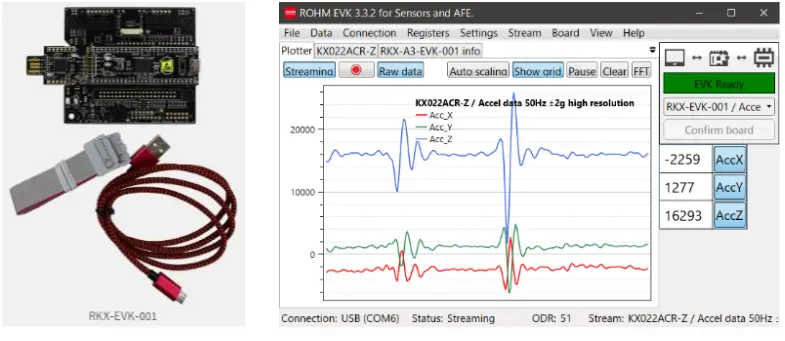
Figure 1 RKX-EVK-001 and ROHM EVK GUI SW
Now*¹, the following evaluation boards are available for ROHM EVK GUI SW.
- KX022ACR-EVK-001, KX132ACR-EVK-001, KX134ACR-EVK-001
- KXTJ3-1057-EVK-001, KX132-1211-EVK-001, KX134-1211-EVK-001

Figure 2 ROHM accelerometer evaluation board
*¹ As of January 2025. New parts will be available from time to time.
This User’s Guide shows how to use ROHM EVK GUI SW for accelerometer. We also provide the following reference manuals. The links to these manuals are available at Accelerometer Evaluation Kit.
- ROHM EVK SW User’s Guide
ROHM EVK GUI SW is used with several ROHM products. This document provides explanations of common functions. - ROHM EVK HW User’s Guide
This document provides explanations of RKX-EVK-001.
ROHM Accelerometer evaluation board reference information like pin assignment can be obtained from each product page. The links to each product page are available at Accelerometer ICs.
Setup and basic operations
Refer to ROHM EVK SW User’s Guide for setup and basic operations. It’s available at Accelerometer Evaluation Kit. A brief overview is given here.
SW download
Download and install ROHM EVK GUI SW from the following URL. Accelerometer Evaluation Kit
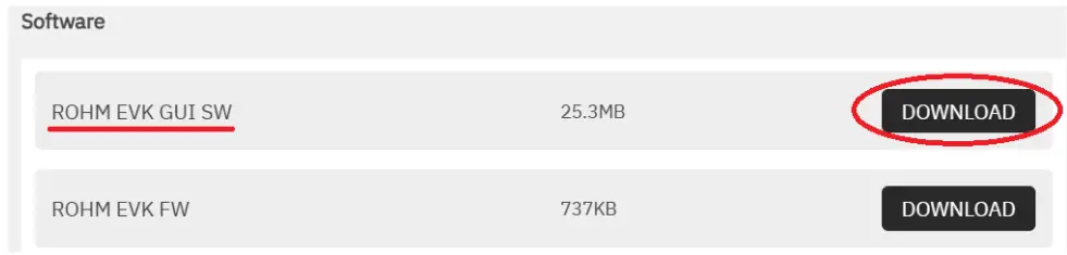
Figure 3 Software download
HW setup
Connect the Accelerometer evaluation board to the RKX-EVK-001 using either Option A or Option B and then connect the USB cable to the PC.

Figure 4 HW Connection
GUI start
Start ROHM EVK GUI SW from the shortcut created on the desktop or from the list of applications.
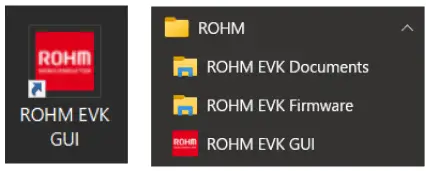
Figure 5 GUI start
EVK connection
Check that ‘EVK Connected’ is displayed in yellow at the top right of the screen. Select Accelerometer EVB and I/F from the drop-down menu. The following is an example of selecting I2C. Click ‘Confirm board’ and check that ‘EVK Ready’ is displayed in green.

When setting a high ODR (e.g., 6400Hz or higher), I2C may not be fast enough. In that case, it is recommended to use SPI.
Part number and Stream selection
From the Stream menu bar, select the connected EVB and choose Stream (preconfigured register settings). As an example, this section explains the ‘Accel data 50Hz ±2g high resolution’ case of KX022ACR-Z.
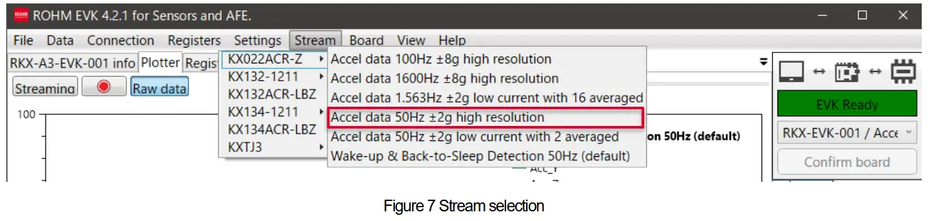
In the Plotter tab, the acceleration waveform is automatically output. Toggling Streaming will turn the acceleration waveform output ON/OFF.

Supporting features
Here are some useful features.
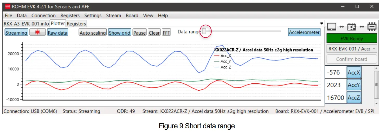
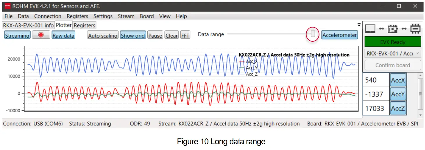
Data range (Time)
With the slider, it is possible to adjust the amount of data points shown in the plotter.
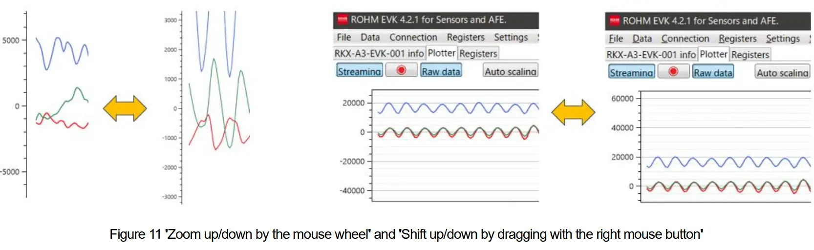
Output range (Acceleration)
The acceleration output range on the screen can be changed by using the mouse wheel. The acceleration output position on the screen can be shifted up and down by dragging up and down with the right mouse button.
Logging
ROHM EVK GUI SW has a logging function for acceleration data.
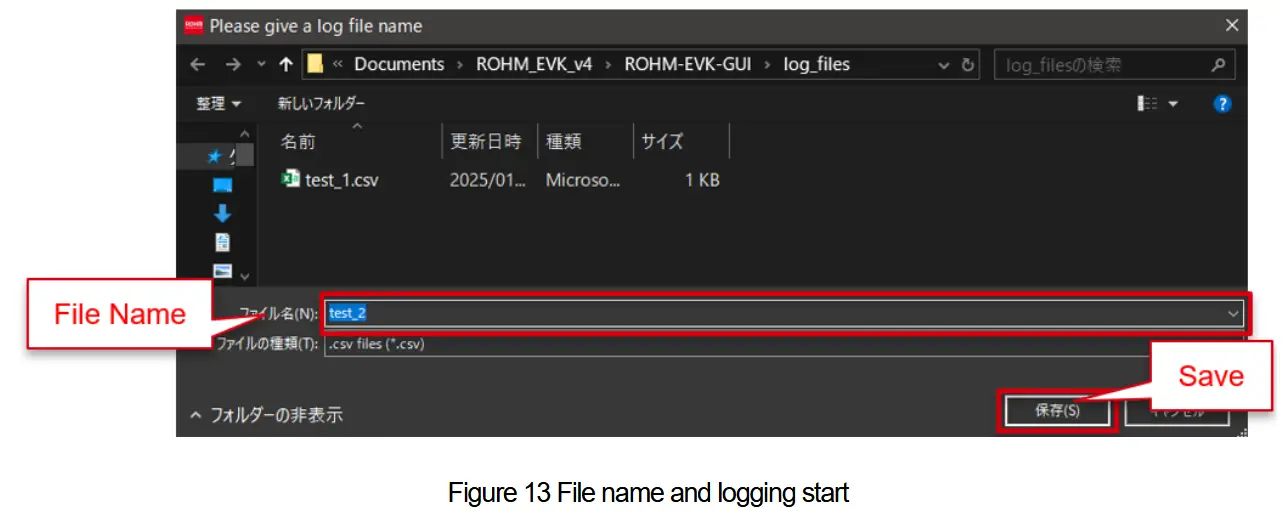
File name and logging start
When you press the red circle, the screen for setting the file name to save the acceleration data log will open. Keyboard shortcut is CTRL + L.

After entering the file name, press save to start logging. The file will be saved at the following address.
C:\Users\(Username)\Documents\ROHM_EVK_v4\ROHM-EVK-GUI\log_files
(Username) is username of the PC. When the software version is updated, ROHM_EVK_v4 may be replaced with, for example, ROHM_EVK_v5.
Logging stop
When you press the red circle again, logging will stop. Keyboard shortcut is also CTRL + L.
Registers change
This section explains how to change the accelerometer registers
Registers
Select Registers while the acceleration output is enabled (Streaming ON). Please note that if you change the registers while the acceleration output is disabled (Streaming OFF), the changes will not be reflected because the settings of the selected Stream will be overwritten when Streaming is turned ON.

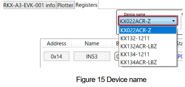
Device name
If the target device is not displayed in the Device name, select Device name from the drop-down menu.
Standby mode
To reflect the current register settings on the screen, press Read in CNTL1 at 0x18.

Uncheck PC1 in CNTL1 at 0x18 to enter standby mode, and press Write.

Registers change
Select, check, or enter the register value for the register you want to change, and press Write. Here is an example of changing the OSA (Accelerometer output data rate) from 100Hz to 12.5Hz.

When changing multiple registers, you can press Write all at the top of the screen at the end instead of pressing Write each time.

Operation mode
After completing all the register settings, check PC1 in CNTL1 at 0x18 to enter operation mode, and press Write.
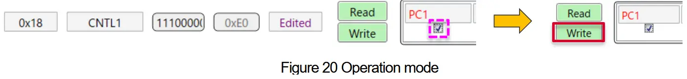
When you select the Plotter tab, the output after changing the registers is displayed. The original Stream name remains, but it is displayed as (MODIFIED), indicating that the register changes have been applied.

Note: Toggling Raw data will change the acceleration unit. Please note that when using SI units, changing the g-range will result in the output level on the screen not being correctly reflected. The g-range has been correctly changed, so if you switch to counts units, the correct output level will be shown on the screen. When changing the g-range, it is recommended to use counts units.

Note: If a too high ODR is set, a pop-up will appear (e.g., 6400Hz or higher in I2C). Pressing ESC will dismiss the pop-up, but the desired ODR has not been reached. Please take measures such as switching to SPI.

Wake-up and Back-to-sleep
This section explains Wake-up and Back-to-sleep. Wake-up and Back-to-sleep are available on the following accelerometers (KX022ACR-Z, KX132ACR-LBZ, KX134ACR-LBZ, KX132-1211 and KX134-1211). KXTJ3-1057 only supports Wake-up and does not support Back-to-sleep. As an example, this section explains the case of the KX022ACR-Z.
Stream selection
Select Wake-up from Stream.

Wake-up pop-up
When you lightly shake the accelerometer EVB by hand, Wake-up event occurs, and pop-up is displayed.

When the accelerometer EVB is then held still, Back-to-sleep event occurs, and the pop-up disappears. By changing the registers, you can customize the threshold and timer (e.g., WUFTH, WUFC) to your preferred values.
Yellow line
In the case of KX022ACR-Z, the yellow line represents the decimal value of STATUS_REG (15h). In Figure 26, the outputs of X-axis and Y-axis are masked to make the waveform easier to see. Positions A, B, C, and D indicate the locations of the yellow line.

In Figure 27, STATUS_REG (15h) values at each position are represented bitwise.

The INT bit becomes 1 when an interrupt occurs. The WAKE bit becomes 1 after a Wake-up event and becomes 0 after a Back-to-sleep event.
Revision history

Notice
- The information contained in this document is intended to introduce ROHM Group (hereafter referred to asROHM) products. When using ROHM products, please verify the latest specifications or datasheets before use.
- ROHM products are designed and manufactured for use in general electronic equipment and applications (such as Audio Visual equipment, Office Automation equipment, telecommunication equipment, home appliances, amusement devices, etc.) or specified in the datasheets. Therefore, please contact the ROHM sales representative before using ROHM products in equipment or devices requiring extremely high reliability and whose failure or malfunction may cause danger or injury to human life or body or other serious damage (such as medical equipment, transportation, traffic, aircraft, spacecraft, nuclear power controllers, fuel control, automotive equipment including car accessories, etc. hereafter referred to as Specific Applications). Unless otherwise agreed in writing by ROHM in advance, ROHM shall not be in any way responsible or liable for any damages, expenses, or losses incurred by you or third parties arising from the use of ROHM Products for Specific Applications.
- Electronic components, including semiconductors, can fail or malfunction at a certain rate. Please be sure to implement, at your own responsibilities, adequate safety measures including but not limited to fail-safe design against physical injury, and damage to any property, which a failure or malfunction of products may cause.
- The information contained in this document, including application circuit examples and their constants, is intended to explain the standard operation and usage of ROHM products, and is not intended to guarantee, either explicitly or implicitly, the operation of the product in the actual equipment it will be used. As a result, you are solely responsible for it, and you must exercise your own independent verification and judgment in the use of such information contained in this document. ROHM shall not be in any way responsible or liable for any damages, expenses, or losses incurred by you or third parties arising from the use of such information.
- When exporting ROHM products or technologies described in this document to other countries, you must abide by the procedures and provisions stipulated in all applicable export laws and regulations, such as the Foreign Exchange and Foreign Trade Act and the US Expor t Administration Regulations, and follow the necessary procedures in accordance with these provisions.
- The technical information and data described in this document, including typical application circuits, are examples only and are not intended to guarantee to be free from infringement of third parties intellectual property or other rights. ROHM does not grant any license, express or implied, to implement, use, or exploit any intellectual property or other rights owned or controlled by ROHM or any third parties with respect to the information contained herein.
- No part of this document may be reprinted or reproduced in any form by any means without the prior written consent of ROHM.
- All information contained in this document is current as of the date of publication and subject to change without notice. Before purchasing or using ROHM products, please confirm the latest information with the ROHM sales representative.
- ROHM does not warrant that the information contained herein is error-free. ROHM shall not be in any way responsible or liable for any damages, expenses, or losses incurred by you or third parties resulting from errors contained in this document.
![]() Thank you for your accessing to ROHM product informations.
Thank you for your accessing to ROHM product informations.
More detail product informations and catalogs are available, please contact us.
ROHM Customer Support System
https://www.rohm.com/contactus
www.rohm.com
© 2023 ROHM Co., Ltd. All rights reserved.
Documents / Resources
 |
ROHM RKX-EVK-001 Kionix EVK GUI SW for Accelerometer [pdf] User Guide RKX-EVK-001, RKX-EVK-001 Kionix EVK GUI SW for Accelerometer, Kionix EVK GUI SW for Accelerometer, EVK GUI SW for Accelerometer, GUI SW for Accelerometer |