ROHM EV Two-Wheeler Light Control Module Reference Board
Specifications
- Product Name: EV Two-Wheeler Light Control Module (LCM) Reference Board
- Key Blocks: Head Lamp, Day Time Running Lamp (DRL), Tail Lamp, Turn Indicator, Acoustic Vehicle Alerting System (AVAS)
- LED Driver ICs Used: BD18354, BD18347, BD18327
- MCU Interface: I2C
- Speech IC: ML22120TBZ0B-MX
Product Usage Instructions
Head Lamp:
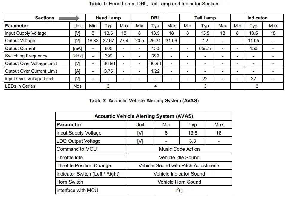
The Head Lamp consists of four LEDs in series with a 150mA string current. It is driven by the ROHM constant current driver (BD18354) using Boost-To-Vin topology.
Day Time Running Lamp (DRL):
The DRL uses a 4-ch constant current LED Driver (BD18347) with each channel configured for 70mA. The current limit is set by a 27k resistor.
Tail Lamp:
The Tail Lamp section also uses the BD18347 LED Driver, with each channel configured for 70mA. The current limit is set by a 27k resistor.
Turn Indicator:
The Turn Indicator operation is controlled by the ROHM LED Driver IC (BD18327) with protection features for LED open and short detections. It offers programmable blinking ON Duty cycle and adjusts PWM ON Duty under high input voltage conditions.
Acoustic Vehicle Alerting System (AVAS):
The AVAS feature is integrated with the main MCU using an I2C interface with a speech IC (ML22120TBZ0B-MX). Customized sound codes can be saved in a SPI Flash memory for generating alerts based on MCU inputs.
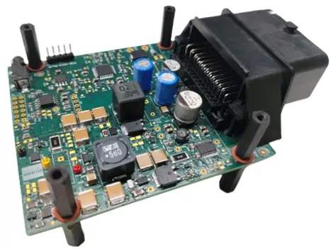
EV Two-Wheeler Light Control Module (LCM)
Reference Board
- This user guide contains instructions for using ROHM’s latest EV Two Wheelers (2W) Light Control Module (LCM) reference design (REF67013) with a built-in Acoustic Vehicle Alerting System (AVAS) feature. The evaluation board (EV2W_LCM-EVK-A05) will enable users to understand performance characteristics under various test conditions of the ROHM Head Lamp, DRL Driver (BD18354MUF), and Tail.
- Lamp Driver (BD18347AEFV), Turn Indicator Driver (BD18327EFV), Animation LED Driver (BD18333EUV) for automotive lighting applications. Devices used in this design are of automotive grade.
Applications
- Automotive LED Exterior Lamp
- Automotive LED Interior Lamp
- 2-Wheeler Turn Indicator
- 2-Wheeler AVAS
Block Diagram
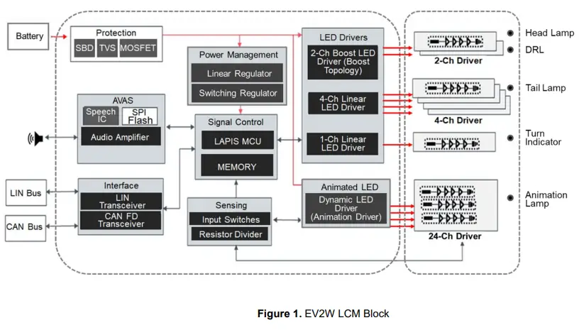
EV 2W Light Control Module (LCM) Reference Board
The design includes the following key blocks, namely Head Lamp, Day Time Running Lamp (DRL), Tail Lamp, Turn Indicator, and Acoustic Vehicle Alerting System (AVAS) as described below.
Head Lamp
The Head Lamp comprises three LEDs in series operating with 800mA string current, which uses a ROHM constant current driver (BD18354) to drive a Boost-To-Vin Topology. The driver switches the converter from 100kHz to 2.25MHz with a minimum pulse width support for 10µsec.
Day Time Running Lamp (DRL)
It comprises four LEDs in series with a 150mA string current. ROHM’s constant current driver (BD18354) has been used to drive the DRL by using the Boost-To-Vin topology.
Tail-LampThe
Tail Lamp section uses a 4-ch constant current LED Driver (BD18347). Each channel can be configured for a maximum current of 150mA. Programmed by SETx Pins, this solution has each channel configured for 70mA. A 27kΩ resistor has been used to set the current limit of 70mA.
Turn Indicator
This design uses the ROHM LED Driver IC (BD18327) for Turn Indicator operation. It comes with a protection feature for LED open and LED short detections. This design is capable of creating a programmable blinking ON Duty cycle. In the case of LED open detection, the output blinking rate has been doubled. Under high input voltage conditions, the output PWM ON Duty reduces to control heat dissipation across the IC and protect the LED load.
Acoustic Vehicle Alerting System (AVAS)
The Acoustic Vehicle Alerting System (AVAS) feature is integrated with the main MCU using an I2C interface with a speech IC (ML22120TBZ0B-MX). The customized sound codes can be saved in a SPI Flash memory that has been interfaced with a speech IC. According to MCU command inputs, dedicated sounds such as Turn Indicator alerts, Horn, or Throttle sounds can be generated in real time with varying pitches.
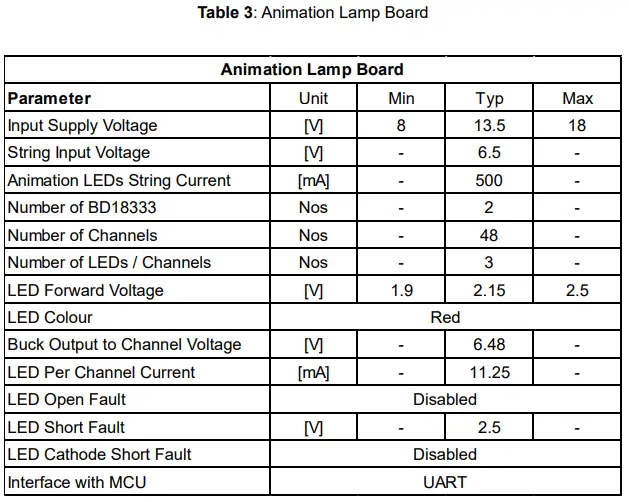
Animation Board
A separate Animation Module kit can be connected to the EV2W LCM board utilizing the UART interface with the existing MCU. A power converter with a step-down DC/DC topology can be used to power up the LED String in the Animation kit. For more information on the Animation module working and design file, you may refer to the ROHM reference design (REF66006-BD18333EUV-M). This reference design uses a 24-channel independently controllable LED driver (BD18333EUV-M), which can be utilized for improving the performance of the LED Rear Lamp, Turn Indicator, or Stop Lamp.
EV 2W Light Control Module (LCM) Reference Board
Evaluation Board
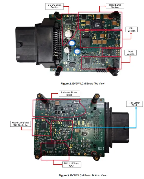
Figure 2 shows the top view of the EV2W LCM Board. It highlights Head Lamp, DRL, AVA, S, and DC-DC Buck converter blocks. Head Lamp power stage layout has been implemented by considering the minimum distance and to avoid parasitic effects. The switching and AVAS sections are placed in different blocks. Figure 3 shows the bottom view of the EV2W LCM board. It includes Turn Indicator Driver, Tail Lamp Driver, Head Lamp, and DRL controller, along with LIN and CAN devices.
Evaluation Board Operating Condition
Operating procedure
This EV2W LCM Board highlights the following blocks: Head Lamp, Tail Lamp, Turn Indicators, DRL, Animation Lamp, and AVAS. It can be operated with the interface switches, throttle, and brakes. For AVAS output, we can interface the speakers with the 3.5mm mono audio jack. The following steps have been suggested as guidance to operate the EV2W LCM Board.
- Check the wiring by referring to Tables 4A and 4 B. (Ensure the connection of peripherals: Head Lamp, Turn Indicators, DRL, Tail Lamp, Interface switches, Animation Tail LEDs, and speakers).
- Connect a 13.5 V / 2A DC Power source to Bat(+) and Bat(-) Pins.
- Turn on the DC power supply source.
- AVAS Sound for the vehicle idle state can be heard.
- Use the throttle to observe the AVAS sound pitch changes as per the throttle rev.
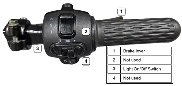
- Enable the Light On/Off switch to enable Head Lamp, DRL, Tail Lamp & Animation LEDs.The
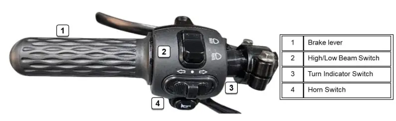
- head lamp’s high beam and low beam can be changed by toggling the High/Low beam switch.
- Brakes can be pressed to see the Tail Lamp intensity increase during braking conditions.
- Turn Indicators can be enabled by using the Left & Right Indicator switch, and the AVAS alert sound can be heard at the same time.
- The horn switch can be pressed to get the sound output from the speakers.
- Brakes can be pressed to see the Tail Lamp intensity increase during braking conditions.

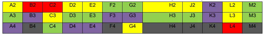
Connection Details
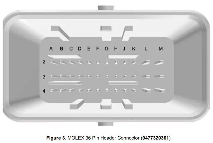
Table 4A: 36 Pin Connector Terminals (0477320361)
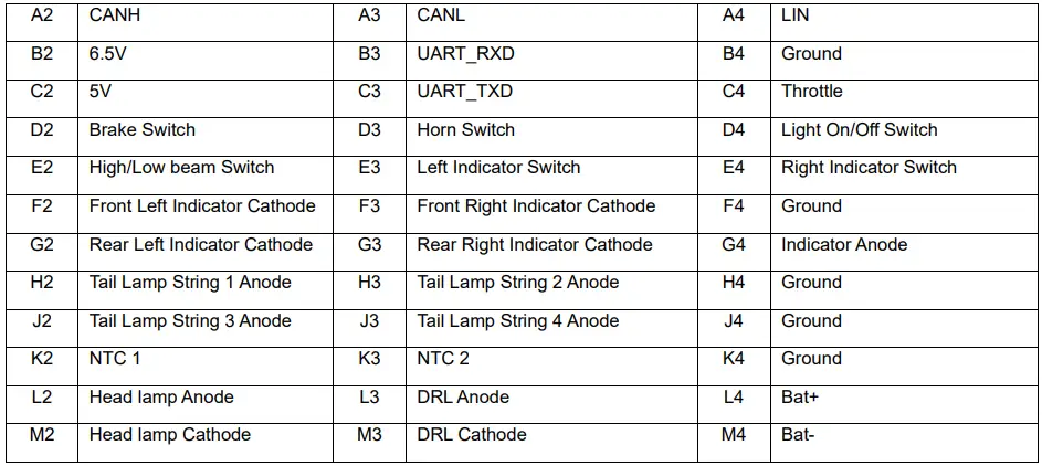
Table 4B: 36 Pin Connector Terminals (0477320361)
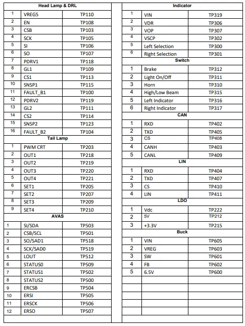
Test Points used in PCB
Table 5: PCB Test Points
Notice
- The information contained in this document is intended to introduce ROHM Group (hereafter referred to as ROHM) products. When using ROHM products, please verify the latest specifications or datasheets before use.
- ROHM products are designed and manufactured for use in general electronic equipment and applications (such as Audio Visual equipment, Office Automation equipment, telecommunication equipment, home appliances, amusement devices, etc.) or specified in the datasheets. Therefore, please contact the ROHM sales representative before using ROHM products in equipment or devices requiring extremely high reliability and whose failure or malfunction may cause danger or injury to human life or body or other serious damage (such as medical equipment, transportation, traffic, aircraft, spacecraft, nuclear power controllers, fuel control, automotive equipment including car accessories, etc. hereafter referred to as Specific Applications). Unless otherwise agreed in writing by ROHM in advance, ROHM shall not be in any way responsible or liable for any damages, expenses, or losses incurred by you or third parties arising from the use of ROHM Products for Specific Applications.
- Electronic components, including semiconductors, can fail or malfunction at a certain rate. Please be sure to implement, at your responsibility, adequate safety measures, including but not limited to fail-safe design against physical injury, and damage to any property, which a failure or malfunction of products may cause.
- The information contained in this document, including application circuit examples and their constants, is intended to explain the standard operation and usage of ROHM products, and is not intended to guarantee, either explicitly or implicitly, the operation of the product in the actual equipment it will be used. As a result, you are solely responsible for it, and you must exercise your independent verification and judgment in the use of such information contained in this document. ROHM shall not be in any way responsible or liable for any damages, expenses, or losses incurred by you or third parties arising from the use of such information.
- When exporting ROHM products or technologies described in this document to other countries, you must abide by the procedures and provisions stipulated in all applicable export laws and regulations, such as the Foreign Exchange and Foreign Trade Act and the US Export Administration Regulations, and follow the necessary procedures under these provisions.
- The technical information and data described in this document, including typical application circuits, are examples only and are not intended to guarantee that to are free from infringement of third parties’ intellectual property or other rights. ROHM does not grant any license, express or implied, to implement, use, or exploit any intellectual property or other rights owned or controlled by ROHM or any third parties concerning the information contained herein.
- No part of this document may be reprinted or reproduced in any form by any means without the prior written consent of ROHM.
- All information contained in this document is current as of the date of publication and subject to change without notice. Before purchasing or using ROHM products, please confirm the latest information with the ROHM sales representative.
- ROHM does not warrant that the information contained herein is error-free. ROHM shall not be in any way responsible or liable for any damages, expenses, or losses incurred by you or third parties resulting from errors contained in this document.
Thank you for accessing ROHM product information. More detailed product informations and catalogs are available; please contact us.
ROHM Customer Support System
- © 2023 ROHM Co., Ltd. All rights reserved.
FAQs
Q: Can I adjust the brightness of the Head Lamp?
A: The brightness of the Head Lamp is fixed based on the design specifications and cannot be adjusted.
Q: How do I configure the Turn Indicator blinking rate?
A: The Turn Indicator blinking rate is programmable; refer to the design documentation for details on adjusting the blinking rate.
Documents / Resources
 |
ROHM EV Two Wheeler Light Control Module Reference Board [pdf] User Guide REF67013, EV2W_LCM-EVK-A05, BD18354MUF, BD18347AEFV, BD18327EFV, BD18333EUV, ML22120TBZ0B-MX, EV Two Wheeler Light Control Module Reference Board, EV Two Wheeler Light Control Module, LCM, Reference Board |