Rockwell Automation 1794-ACN15 FLEX IO ControlNet Adapter
Specifications
- Catalog Numbers: 1794-ACN15, 1794-ACNR15, 1794-ACNR15XT, series D
Product Information
Overview
- The FLEX I/O ControlNet Adapters are designed to provide ControlNet network connectivity for various industrial applications.
Mounting Dimensions
- The adapter can be mounted on a DIN rail, panel, or wall, allowing for flexible installation options.
Wire the Adapter
- Properly wire the adapter following the installation instructions to ensure correct functionality.
Interpret the Status Indicators
- Understand the status indicators on the adapter to monitor its operation effectively.
Product Usage Instructions
Install Your Adapter
- Ensure all debris is kept away during mounting to prevent damage.
Mounting on a DIN Rail
- To mount on a DIN rail, follow the provided mounting dimensions and secure the adapter accordingly.
Mounting on a Panel or Wall
- If mounting on a panel or wall, use appropriate mounting hardware and follow the installation guidelines.
Mount or Replace the Adapter on an Existing System
- When integrating the adapter into an existing system, carefully replace or mount it following the provided instructions.
Wire the Adapter
- Connect the necessary wires to the adapter as per the wiring diagram provided in the installation instructions.
Interpret the Status Indicators
- Refer to the user manual to understand the meaning of different status indicators on the adapter.
Warning
 ATTENTION
Read this document and the documents listed in the Additional Resources section about installation, configuration and operation of this equipment before you install, configure, operate or maintain this product. Users are required to familiarize themselves with installation and wiring instructions in addition to requirements of all applicable codes, laws, and standards.
Activities including installation, adjustments, putting into service, use, assembly, disassembly, and maintenance are required to be carried out by suitably trained personnel in accordance with applicable code of practice. If this equipment is used in a manner not specified by the manufacturer, the protection provided by the equipment may be impaired.
Read this document and the documents listed in the Additional Resources section about installation, configuration, and operation of this equipment before you install, configure, operate, or maintain this product. Users are required to familiarize themselves with installation and wiring instructions in addition to requirements of all applicable codes, laws, and standards. Installation, adjustments, putting into service, use, assembly, disassembly, and maintenance are required to be carried out by suitably trained personnel in accordance with applicable code of practice. In case of malfunction or damage, no attempts at repair should be made. The module should be returned to the manufacturer for repair. Do not dismantle the module.
Environment and Enclosure
![]() ATTENTION: This equipment is intended for use in a Pollution Degree 2 industrial environment, in overvoltage Category II applications (as defined in EN/IEC 60664-1), at altitudes up to 2000 m (6562 ft) without derating.
ATTENTION: This equipment is intended for use in a Pollution Degree 2 industrial environment, in overvoltage Category II applications (as defined in EN/IEC 60664-1), at altitudes up to 2000 m (6562 ft) without derating.
This equipment is not intended for use in residential environments and may not provide adequate protection to radio communication services in such environments.
This equipment is supplied as open-type equipment for indoor use. It must be mounted within an enclosure that is suitably designed for those specific environmental conditions that will be present and appropriately designed to prevent personal injury resulting from accessibility to live parts. The enclosure must have suitable flame-retardant properties to prevent or minimize the spread of flame, complying with a flame spread rating of 5VA or be approved for the application if nonmetallic. The interior of the enclosure must be accessible only by the use of a tool. Subsequent sections of this publication may contain more information regarding specific enclosure type ratings that are required to comply with certain product safety certifications.
In addition to this publication, see:
- Industrial Automation Wiring and Grounding Guidelines, publication 1770-4.1, for more installation requirements.
- NEMA Standard 250 and EN/IEC 60529, as applicable, for explanations of the degrees of protection provided by enclosures.
Prevent Electrostatic Discharge
![]() ATTENTION: This equipment is sensitive to electrostatic discharge, which can cause internal damage and affect normal operation. Follow these guidelines when you handle this equipment:
ATTENTION: This equipment is sensitive to electrostatic discharge, which can cause internal damage and affect normal operation. Follow these guidelines when you handle this equipment:
- Touch a grounded object to discharge potential static.
- Wear an approved grounding wriststrap.
- Do not touch connectors or pins on component boards.
- Do not touch circuit components inside the equipment.
- Use a static-safe workstation, if available.
- Store the equipment in appropriate static-safe packaging when not in use.
![]() ATTENTION: This product is grounded through the DIN rail to chassis ground. Use zinc-plated chromate-passivated steel DIN rail to assure proper grounding. The use of other DIN rail materials (for example, aluminum or plastic) that can corrode, oxidize, or are poor conductors, can result in improper or intermittent grounding. Secure DIN rail to mounting surface approximately every 200 mm (7.8 in.) and use end-anchors appropriately. Be sure to ground the DIN rail properly. See Industrial Automation Wiring and Grounding Guidelines, publication 1770-4.1, for more information.
ATTENTION: This product is grounded through the DIN rail to chassis ground. Use zinc-plated chromate-passivated steel DIN rail to assure proper grounding. The use of other DIN rail materials (for example, aluminum or plastic) that can corrode, oxidize, or are poor conductors, can result in improper or intermittent grounding. Secure DIN rail to mounting surface approximately every 200 mm (7.8 in.) and use end-anchors appropriately. Be sure to ground the DIN rail properly. See Industrial Automation Wiring and Grounding Guidelines, publication 1770-4.1, for more information.
![]() ATTENTION: Electrical Safety Considerations
ATTENTION: Electrical Safety Considerations
Power to this equipment and all connected I/O must be supplied from a source compliant with the following:
- SELV source approved to EN/IEC60950-1, EN/IEC61010-2-201, or EN/IEC62368-1 (ES1)
- PELV source approved to EN/IEC60950-1, EN/IEC61010-2-201, or EN/IEC62368-1 (ES1)
Note: A power source approved to a U.S.A. or Canadian version of the above listed standards is required for system approval in the U.S.A. or Canada.
- All wiring must comply with applicable electrical installation requirements (for example, N.E.C. article 501-4(b)).
- Wire conductor and insulation ratings shall support minimum temperature rating of 105 °C (221 °F).
![]() WARNING
WARNING
- For Class I Division 2 applications, use only Class I Division 2 listed or recognized accessories and modules approved for use within the FLEX™ I/O platform.
- If you insert or remove the module while backplane power is on, an electric arc can occur. This could cause an explosion in hazardous location installations. Be sure that power is removed or the area is nonhazardous before proceeding.
- If you connect or disconnect the communications cable with power applied to this module or any device on the network, an electric arc can occur. This could cause an explosion in hazardous location installations. Be sure that power is removed or the area is nonhazardous before proceeding.
- If you connect or disconnect wiring while the field-side power is on, an electric arc can occur. This could cause an explosion in hazardous location installations. Be sure that power is removed or the area is nonhazardous before proceeding.
- When used in a Class I Division 2, hazardous location, this equipment must be mounted in a suitable enclosure with proper wiring method that complies with the governing electrical codes.
![]() ATTENTION: Use only a soft dry anti-static cloth to wipe down equipment. Do not use any cleaning agents.
ATTENTION: Use only a soft dry anti-static cloth to wipe down equipment. Do not use any cleaning agents.
![]() WARNING: Special Conditions for Safe Use:
WARNING: Special Conditions for Safe Use:
- This equipment shall be mounted in an UKEX/ATEX/IECEx Zone 2 certified enclosure with a minimum ingress protection rating of at least IP54 (in accordance with EN/IEC 60079-0) and used in an environment of not more than Pollution Degree 2 (as defined in EN/IEC 60664-1) when applied in Zone 2 environments. The enclosure must be accessible only by the use of a tool.
- This equipment shall be used within its specified ratings defined by Rockwell Automation.
- Transient protection shall be provided that is set at a level not exceeding 140% of the peak rated voltage value at the supply terminals to the equipment.
- The instructions in the user manual shall be observed.
- This equipment must be used only with UKEX/ATEX/IECEx certified Rockwell Automation backplanes.
- Secure any external connections that mate to this equipment by using screws, sliding latches, threaded connectors, or other means provided with this product.
- Do not disconnect equipment unless power has been removed or the area is known to be nonhazardous.
- Earthing is accomplished through mounting of modules on rail.
UK and European Hazardous Location Approval
The following applies to products marked![]() II 3 G:
II 3 G:
- Are Equipment Group II, Equipment Category 3, and comply with the Essential Health and Safety Requirements relating to the design and construction of such equipment given in Schedule 1 of UKEX and Annex II of EU Directive 2014/34/EU. See the UKEx and EU Declaration of Conformity at rok.auto/certifications for details.
- The type of protection is Ex ec IIC T4 Gc according to EN IEC 60079-0:2018, EXPLOSIVE ATMOSPHERES – PART 0: EQUIPMENT – GENERAL REQUIREMENTS, Issue Date 07/2018 and EN IEC 60079-7:2015+A1:2018, Explosive atmospheres. Equipment protection by increased safety “e”.
- Comply with Standard EN IEC 60079-0:2018, EXPLOSIVE ATMOSPHERES – PART 0: EQUIPMENT – GENERAL REQUIREMENTS, Issue Date 07/2018, EN IEC 60079- 7:2015+A1:2018 Explosive atmospheres. Equipment protection by increased safety “e”, reference certificate number DEMKO 14 ATEX 1342501X and UL22UKEX2378X.
- Are intended for use in areas in which explosive atmospheres caused by gases, vapors, mists, or air are unlikely to occur, or are likely to occur only infrequently and for short periods. Such locations correspond to Zone 2 classification according to UKEX regulation 2016 No. 1107 and ATEX directive 2014/34/EU.
IEC Hazardous Location Approval
The following applies to products marked with IECEx certification:
- Are intended for use in areas in which explosive atmospheres caused by gases, vapors, mists, or air are unlikely to occur, or are likely to occur only infrequently and for short periods. Such locations correspond to Zone 2 classification to IEC 60079-0.
- The type of protection is Ex ec IIC T4 Gc according to IEC 60079-0 and IEC 60079-7.
- Comply with Standards IEC 60079-0, Explosive atmospheres Part 0: Equipment – General requirements, Edition 7, Revision Date 2017, IEC 60079-7, 5.1 Edition revision date 2017, Explosive atmospheres – Part 7: Equipment protection by increased safety “e”, reference IECEx certificate number IECEx UL 14.0066X.
North American Hazardous Location Approval
The Following Information Applies When Operating This Equipment In Hazardous Locations.
Products marked “CL I, DIV 2, GP A, B, C, D” are suitable for use in Class I Division 2 Groups A, B, C, D, Hazardous Locations and nonhazardous locations only. Each product is supplied with markings on the rating nameplate indicating the hazardous location temperature code. When combining products within a system, the most adverse temperature code (lowest “T” number) may be used to help determine the overall temperature code of the system. Combinations of equipment in your system are subject to investigation by the local Authority Having Jurisdiction at the time of installation.
![]() WARNING: Explosion Hazard
WARNING: Explosion Hazard
- Do not disconnect equipment unless power has been removed or the area is known to be nonhazardous.
- Do not disconnect connections to this equipment unless power has been removed or the area is known to be nonhazardous. Secure any external connections that mate to this equipment by using screws, sliding latches, threaded connectors, or other means provided with this product.
- Substitution of components may impair suitability for Class I Division 2.
Overview
FLEX I/O ControlNet® single and redundant adapters (1794-ACN15, 1794-ACNR15, 1794-ACNR15XT, series D, firmware revision 10.3) function as drop-in replacements for series C adapters and continue to support 32-bit modules and numerical display of the firmware revision in RSNetWorx™ for ControlNet (revision 3.21 or later).
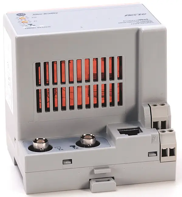
FLEX I/O ControlNet Adapter – 1794-ACN15, 1794-ACNR15, 1794-ACNR15XT, Series D

Component Identification
| Description | Description | ||
| 1 | ControlNet node selection dial | 5 | ControlNet programming terminal network access port (NAP) |
| 2 | Indicators | 6 | +24V DC connections |
| 3A | ControlNet network cable BNC connector A | 7 | 24V common connections |
| 3B | ControlNet network cable BNC connector B(1) | 8 | Flexbus connector |
| 4 | Adapter locking tab | ||
(1) The ControlNet network cable BNC connector B is available on 1794-ACNR15 and 1794-ACNR15XT adapters only.
Install Your Adapter
Read this for information on how to install the FLEX ControlNet adapter.

![]() ATTENTION: During mounting of all devices, be sure that all debris (metal chips, wire strands, and so on) is kept from falling into the module. Debris that falls into the module could cause damage on power-up.
ATTENTION: During mounting of all devices, be sure that all debris (metal chips, wire strands, and so on) is kept from falling into the module. Debris that falls into the module could cause damage on power-up.
Mounting Dimensions
The adapters have the following mounting dimensions:

Mount on a DIN Rail
- Position the ControlNet adapter (A) on an IEC standard (35 x 7.5 x 1 mm) top-hat DIN rail (B), Allen-Bradley® part number 199-DR1; 46277-3; EN50022, at a slight angle.
- Hook the lip on the rear of the adapter onto the top of the DIN rail, and rotate the adapter onto the rail.
- Press the adapter down onto the DIN rail until flush. Locking tab (C) snaps the adapter into position and locks it onto the DIN rail.
- If the adapter does not lock in place, use a screwdriver or similar device to move the locking tab down while pressing the adapter flush onto the DIN rail, and release the locking tab to lock the adapter in place. If necessary, push up on the locking tab to lock.
- Connect the adapter wiring. See Wire the Adapter.
Mount on a Panel or Wall
- To mount the adapter to a panel or wall, see Panel Mounting Kit Cat. No. 1794-NM1/B Installation Instructions, publication 1794-IN135.
Mount or Replace the Adapter on an Existing System
- Disconnect any wiring jumpered to the adjacent terminal base.
- Disconnect the BNC connectors from the front of the adapter.
- Open the module latching mechanism and remove the module from the base unit to which the adapter is attached.
- Push the Flexbus connector toward the right side of the terminal base to unplug the backplane connection.
- Release the locking tab and remove the adapter.
Before installing the new adapter, notice the notch on the right rear of the adapter. This notch accepts the hook on the terminal base unit. The notch is open at the bottom. The hook and adjacent connection point keep the terminal base and the adapter tight together, reducing the possibility of a break in communication over the backplane.
- Push down and in at the same time to lock the adapter to the DIN rail.
- If the adapter does not lock in place, use a screwdriver or similar device to move the locking tab down while pressing the adapter flush onto the DIN rail, and release the locking tab to lock the adapter in place. If necessary, push up on the locking tab to lock.
 When the adapter is locked onto the DIN rail, gently push the Flexbus connector into the adapter to complete the backplane.
- If the adapter does not lock in place, use a screwdriver or similar device to move the locking tab down while pressing the adapter flush onto the DIN rail, and release the locking tab to lock the adapter in place. If necessary, push up on the locking tab to lock.
- Reinstall the module in the adjacent terminal base unit.
Wire the Adapter

- Connect the ControlNet network cable to connector, terminal A.
- For 1794-ACNR15, 1794-ACNR15XT only: Connect the redundant ControlNet network cable to connector B.
- Connect +V DC power to the left side of the lower connector, terminal D.
- Connect -V common to the left side of the upper connector, terminal C.
- Connections E and F are used to pass -V common (E) and +V DC power (F) to the next module in the series (if necessary).
- Set the network address using the selection dials G. Valid settings range from 01…99.

![]() WARNING
WARNING
- If you connect or disconnect the ControlNet cable with power applied to this adapter or any device on the network, an electric arc can occur. This could cause an explosion in hazardous installations. Be sure that power is removed or the area is nonhazardous before proceeding.
- If you connect or disconnect wiring while the field side power is on, an electric arc can occur. This could cause an explosion in hazardous location installations. Be sure that power is removed or the area is nonhazardous before proceeding.
- When connecting wiring, torque terminal screws C, D, E, and F to 0.8 N•m (7 lb•in.).
- Power wiring must be less than 10 m (32.8 ft) in length.
- Do not wire more than 2 conductors on any single terminal.
![]() ATTENTION: Do not remove or replace a terminal base unit or an adapter while power is applied. Interruption of the backplane can result in unintentional operation or machine motion.
ATTENTION: Do not remove or replace a terminal base unit or an adapter while power is applied. Interruption of the backplane can result in unintentional operation or machine motion.
Interpret the Status Indicators
The adapter has LED indicators to specify its status and aid the user in troubleshooting.

Status Indicators

Specifications
General Specifications — FLEX I/O ControlNet Adapter
| Attribute | Value |
| I/O capacity | 8 modules |
| Supply voltage, input | 19.2…31.2V DC, 400 mA |
| Supply voltage, output | 5V DC, 640 mA |
| Inrush current | 14 A for 2 ms |
| Communication rate | 5 Mbps |
| Status indicators | I/O Status – Red/green Comm A – Red/green Comm B – Red/green |
| Isolation voltage | 50V (continuous), Basic Insulation Type
Type tested @ 860V AC for 60 s, power to system, power to ControlNet, and ControlNet to system No isolation between ControlNet channels |
| Power dissipation, max | 3.4 W @ 19.2V DC |
| Terminal screw torque | 0.8 N•m (7 lb•in) |
|
Wire size |
Power connections:
Single wire connection: 0.33…2.5 mm2 (22…12 AWG) solid or stranded copper wire rated at 105 °C (221 °F) or greater 1.2 mm (3/64 in.) insulation max Double wire connection: 0.33…1.3 mm2 (22…16 AWG) solid or stranded (not intermixed) copper wire rated at 105 °C (221 °F) or greater 1.2 mm (3/64 in.) insulation max |
| Wire category(1) | 3 – on power ports
2 – on communications ports |
| Dimensions, approx. (HxWxD) | 87.4 x 94 x 92 mm (3.44 x 3.7 x 3.6 in.) |
| Weight, approx. | 220 g (7.76 oz) |
| Enclosure type rating | None (open-style) |
| ControlNet cable | Belden RG-6/U |
| North American temp code | T4A |
| UKEX/ATEX temp code | T4 |
| IECEx temp code | T4 |
(1) Use this Conductor Category information for planning conductor routing. See Industrial Automation Wiring and Grounding Guidelines, publication 1770-4.1.
Environmental Specifications
| Attribute | 1794-ACN15, 1794-ACNR15 | 1794-ACNR15XT |
|
Temperature, operating |
IEC 60068-2-1 (Test Ad, Operating Cold),
IEC 60068-2-2 (Test Bd, Operating Dry Heat), IEC 60068-2-14 (Test Nb, Operating Thermal Shock): -25…+55 °C (-13…+131 °F) |
IEC 60068-2-1 (Test Ad, Operating Cold),
IEC 60068-2-2 (Test Bd, Operating Dry Heat), IEC 60068-2-14 (Test Nb, Operating Thermal Shock): -25…+70 °C (-13…+158 °F) |
|
Temperature, nonoperating |
IEC 60068-2-1 (Test Ab, Unpackaged Nonoperating Cold),
IEC 60068-2-2 (Test Bb, Unpackaged Nonoperating Dry Heat), IEC 60068-2-14 (Test Na, Unpackaged Nonoperating Thermal Shock): -40…+85 °C (-40…+185 °F) |
|
| Surrounding air temperature, max | 55 °C (131 °F) | 70 °C (158 °F) |
| Relative humidity | IEC 60068-2-30 (Test Db, Unpackaged Damp Heat): 5…95% noncondensing | |
| Vibration | IEC60068-2-6 (Test Fc, Operating): 5 g @ 10…500 Hz | |
| Shock, operating | IEC60068-2-27 (Test Ea, Unpackaged shock): 30 g | |
| Shock, nonoperating | IEC60068-2-27 (Test Ea, Unpackaged shock): 50 g | |
| Emissions | IEC 61000-6-4 | |
| ESD immunity | IEC 61000-4-2:
6 kV contact discharges 8 kV air discharges |
|
| Radiated RF immunity | IEC 61000-4-3:
10V/m with 1 kHz sine-wave 80% AM from 80…6000 MHz |
|
| Attribute | 1794-ACN15, 1794-ACNR15 | 1794-ACNR15XT |
| EFT/B immunity | IEC 61000-4-4:
±4 kV at 5 kHz on power ports ±2 kV at 5 kHz on communications ports |
|
| Surge transient immunity | IEC 61000-4-5:
±2 kV line-earth (CM) on communications ports |
|
| Conducted RF immunity | IEC 61000-4-6:
10V rms with 1 kHz sine-wave 80% AM from 150 kHz…80 MHz |
|
Certifications
| Certifications (when product is marked)(1) | Value |
| c-UL-us | UL Listed Industrial Control Equipment, certified for US and Canada. See UL File E65584.
UL Listed for Class I Division 2 Group A,B,C,D Hazardous Locations, certified for U.S. and Canada. See UL File E194810. |
|
UK and CE |
UK Statutory Instrument 2016 No. 1091 and European Union 2014/30/EU EMC Directive, compliant with: EN 61326-1; Meas./Control/Lab., Industrial Requirements
EN 61000-6-2; Industrial Immunity EN 61131-2; Programmable Controllers EN 61000-6-4; Industrial Emissions UK Statutory Instrument 2012 No. 3032 and European Union 2011/65/EU RoHS, compliant with: EN 63000; Technical documentation |
| RCM | Australian Radiocommunications Act, compliant with: EN 61000-6-4; Industrial Emissions |
|
Ex |
UK Statutory Instrument 2016 No. 1107 and European Union 2014/34/EU ATEX Directive, compliant with: EN IEC 60079-0; General Requirements
EN IEC 60079-7; Explosive Atmospheres, Protection “e” II 3 G Ex ec IIC T4 Gc DEMKO 14 ATEX 1342501X UL22UKEX2378X |
|
IECEx |
IECEx System, compliant with:
IEC 60079-0; General Requirements IEC 60079-7; Explosive Atmospheres, Protection “e” Ex ec IIC T4 Gc IECEx UL 14.0066X |
| KC | Korean Registration of Broadcasting and Communications Equipment, compliant with: Article 58-2 of Radio Waves Act, Clause 3 |
| Morocco | Arrêté ministériel n° 6404-15 du 29 ramadan 1436
䔂ⵖ䚍❡ㅷ雩霆㹊倶錞ⴭ 旘歏孞 |
| CCC | CNCA-C23-01
CNCA-C23-01 CCC Implementation Rule Explosion-Proof Electrical Products |
(1) See the Product Certification link at rok.auto/certifications for Declarations of Conformity, Certificates, and other certification details.
Additional Resources
For more information on the products that are described in this publication, use these resources. You can view or download publications at rok.auto/literature.
| Resource | Description |
| FLEX I/O and FLEX I/O-XT Selection Guide, publication 1794-SG002 | A description and overview of the 1794 series FLEX I/O and FLEX I/O-XT™ modules and compatible control platforms. |
| Industrial Automation Wiring and Grounding Guidelines, publication 1770-4.1 | Provides general guidelines for installing a Rockwell Automation industrial system. |
| Product Certifications website, rok.auto/certifications | Provides declarations of conformity, certificates, and other certification details. |
Rockwell Automation Support
Use these resources to access support information.
| Technical Support Center | Find help with how-to videos, FAQs, chat, user forums, Knowledgebase, and product notification updates. | rok.auto/support |
| Local Technical Support Phone Numbers | Locate the telephone number for your country. | rok.auto/phonesupport |
| Technical Documentation Center | Quickly access and download technical specifications, installation instructions, and user manuals. | rok.auto/techdocs |
| Literature Library | Find installation instructions, manuals, brochures, and technical data publications. | rok.auto/literature |
| Product Compatibility and Download Center (PCDC) | Download firmware, associated files (such as AOP, EDS, and DTM), and access product release notes. | rok.auto/pcdc |
Documentation Feedback
Your comments help us serve your documentation needs better. If you have any suggestions on how to improve our content, complete the form at rok.auto/docfeedback.
Waste Electrical and Electronic Equipment (WEEE)
 At the end of life, this equipment should be collected separately from any unsorted municipal waste.
Rockwell Automation maintains current product environmental compliance information on its website at rok.auto/pec.
Contact
Connect with us

AMERICAS: Rockwell Automation, 1201 South Second Street, Milwaukee, WI 53204-2496 USA,
- Tel: (1) 414.382.2000
EUROPE/MIDDLE EAST/AFRICA: Rockwell Automation NV, Pegasus Park, De Kleetlaan 12a, 1831 Diegem, Belgium,
- Tel: (32) 2663 0600
ASIA PACIFIC: Rockwell Automation SEA Pte Ltd, 2 Corporation Road, #04-05, Main Lobby, Corporation Place, Singapore 618494,
- Tel: (65) 6510 6608
UNITED KINGDOM: Rockwell Automation Ltd., Pitfield, Kiln Farm, Milton Keynes, MK11 3DR, United Kingdom,
- Tel: (44)(1908) 838-800
FAQ
- Q: Can the adapter be used in hazardous locations?
- A: Yes, the adapter has approvals for hazardous locations. Refer to the manual for specific details.
Documents / Resources
 |
Rockwell Automation 1794-ACN15 FLEX IO ControlNet Adapter [pdf] Installation Guide 1794-ACN15, 1794-ACNR15, 1794-ACNR15XT, 1794-ACN15 FLEX IO ControlNet Adapter, 1794-ACN15, FLEX IO ControlNet Adapter, ControlNet Adapter, Adapter |