
RFID RF-N8204 UHF Reader Instruction Manual

1 Demo Instruction
The Demo mainly carries out the functions of system control, parameter set and get, tag reading and writing, and data display, etc.
Before using the demo, please check whether the reader hardware connection is all done, and pay attention to the following aspects:
- The network parameters are configured correctly (connect WIFI if necessary);
- The antenna ports that need to be used are connected to antennas;
- The reader is power-on( the buzzer is ringing).
2 Demo Applicating Environment
- Software Environment
Windows Server 2003、Windows XP Service Pack 2、Windows 7、Windows10 operating systems. - Hardware Environment
P4/1.7GHz PC with better configuration,512M or larger storage, 40G hard disk.
3 Demo Version
- V0.17.0.0
4 Demo Operation
4.1 Connect Reader
All functions can only be operated after a successful connection.
4.1.1 RS232 Communication Connection
Double click “GReaderDemo.exe” to start the Demo. Grey icons on the main interface means the reader is not connected. Select communication mode “RS232 connection”, “connection parameters”, “COM”( the COM number of the PC chose) in Device Connection. Choose 115200(default) as Baud rate, then click “Confirm”, as figure 4.1.1.1 shows.

Figure 4.1.1.1 RS232 Connection
If the connection is successful, the icons in the tool bar will be colored as figure 4.1.1.2 shows. It means COM is connected. Figure

Figure 4.1.1.2 RS232 Connection success
4.1.2 RS485 Communication Connection
Select communication mode “RS485 connection” in Device Connection, fill in the parameters, and then click “Confirm” to connect the device, as Figure 4.1.2.1 shows. If the connection is successful, the icons will be colored as Figure 4.1.2.2 shows.

Figure 4.1.2.1 RS485 Connection

Figure 4.1.2.2 RS485 Connection success
4.1.3 TCP Client Communication Connection
Select communication mode” TCP client” in the “ connect reader”, “connection parameter”, and fill in” “192.168.1.168:8160 ” (192.168.1.168 is the default IP of the reader, 8160 is the port number). Click “Confirm”, as Figure 4.1.3.1 shows. If the connection is successful, the icons will be colored like Figure 4.1.3.2.

Figure 4.1.3.1 TCP Connection

Figure 4.1.3.2 TCP Connection success
4.2 Data Displaying Area
Click ,the data displaying area will be like Figure 4.2.1.
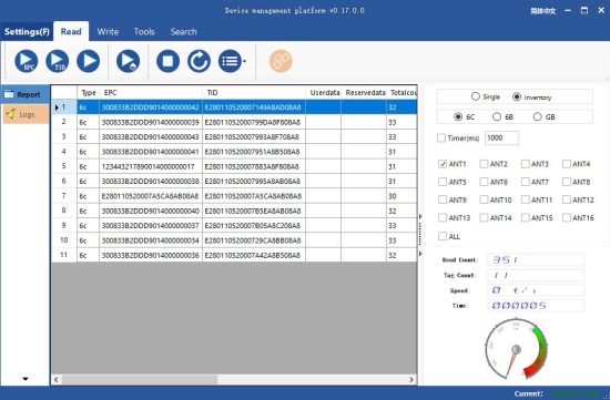
Figure 4.2.1 data displaying area parameter meaning
Type: type of tag:6C, 6B and GB ;
EPC: EPC data of the tag which is readable and writable ;
TID: TID data of the tag, which is a unique identification and readable only ;
Userdata: data of the user area, readable and writable ;
Reservedata: data of the reserved data, to store the tag password, etc. ;
Totalcount: total number of the times the tag read ;
ANT1: number of the times antenna 1 read ;
ANT2: number of the times antenna 2 read ;
ANT3: number of the times antenna 3 read ;
ANT4:number of the times antenna 4 read ;
ANT5: number of the times antenna 5 read ;
ANT6: number of the times antenna 6 read ;
ANT7: number of the times antenna 7 read ;
ANT8: number of the times antenna 8 read ;
RSSI: signal strength ;
Frequency: the frequency of the tag being read ;
Phase: phase value of the tag being read ;
ReadTime: reading time .
4.2.1 Read EPC
Click ![]() , and the EPC being read will be displayed on the data displaying area. It can read the EPC data area of the ISO18000-6C tag and national standard tag.
, and the EPC being read will be displayed on the data displaying area. It can read the EPC data area of the ISO18000-6C tag and national standard tag.
EPC is displayed in hexadecimal strings, and the length is in words (1 word=2 bytes=4 hexadecimal character) .
To read the EPC data of custom length, please refer to Custom Reading for details.
4.2.2 Read TID
Click ![]() , and the EPC and TID data being read will be displayed on the data displaying area. It can read the EPC and TID data area of ISO18000-6B, ISO18000-6C, and national standard tag.
, and the EPC and TID data being read will be displayed on the data displaying area. It can read the EPC and TID data area of ISO18000-6B, ISO18000-6C, and national standard tag.
TID is displayed in hexadecimal strings, and the length is in words (1 word=2 bytes=4 hexadecimal character) . The length of TID is defaulted to be 6 words.
To read the TID data of custom length, please refer to Custom Reading for details.
4.2.3 Custom Read
4.2.3.1 ISO18000-6C Tag
Select ”6C” as tag type , click ![]() , and a dialog box will pop up, like Figure 4.2.3.1. Detail parameter instruction will be as follows:
, and a dialog box will pop up, like Figure 4.2.3.1. Detail parameter instruction will be as follows:
Match parameter, which can be read by matching the known tag data, means that only this tag can be read.
Read TID: select read tag TID data. The reading mode is defaulted to be “self-adaptable” and the reading length is in words, as shown in Figure 4.2.3.1.
Read user data: choose to read the data of the tag user area. The starting address and reading length are in words, as shown in Figure 4.2.3.2.
Read reserved area: select the data of the tag reserve area. The starting address and reading length are in words, as shown in Figure 4.2.3.3.
Access password, the access password for tag checking, as shown in Figure 4.2.3.4.

Figure 4.2.3.1 Custom Reading for EPC Tag (TID)

Figure 4.2.3.2 Custom Reading for EPC Tag (Userdata)

Figure 4.2.3.3 Custom Reading for EPC Tag (reserved area)

Figure 4.2.3.4 Custom Reading for EPC Tag (Access Password/Other)
4.2.3.2 ISO18000-6B Tag
Select ”6B” as tag type, click ![]() , and the dialog box will pop up. As shown in Figure 4.2.3.5. TID data or user data can be selected to read, and TID matching reading can be performed. Users unfamiliar with tag protocol please ignore this function. The starting address and reading length are in words.
, and the dialog box will pop up. As shown in Figure 4.2.3.5. TID data or user data can be selected to read, and TID matching reading can be performed. Users unfamiliar with tag protocol please ignore this function. The starting address and reading length are in words.

Figure 4.2.3.5 Custom Reading for 6B tag
4.2.3.3 GB/T 29768―2013 Tag
Select”GB” as tag tye, click ![]() ,and the dialog box will pop up as shown in Figure 4.2.3.6. TID data or user data can be selected to read, and TID matching reading can be performed.
,and the dialog box will pop up as shown in Figure 4.2.3.6. TID data or user data can be selected to read, and TID matching reading can be performed.

Figure 4.2.3.6 Custom Reading for GB-T 29768―2013 Tag (TID)

Figure 4.2.3.7 Custom Reading for GB-T 29768―2013 Tag (userdata)

Figure 4.2.3.7 Custom Reading for GB-T 29768―2013 Tag (accesss password)
4.2.4 Stop
Click ![]() to stop all RFID operations of the reader and put the reader into an idle state.
to stop all RFID operations of the reader and put the reader into an idle state.
4.3 Write Data
4.3.1 Write EPC Data
Select Write on the main interface -> click ![]() , and the dialog box will pop up as shown in Figure 4.3.1 .
, and the dialog box will pop up as shown in Figure 4.3.1 .

Figure 4.3.1 Write EPC Data
Select data (with TID information) of a tag, fill in EPC data (hexadecimal character string), then click “Confirm”.
4.3.2 Write User Data
Select Write on the main interface -> click ![]() and the dialog box will pop up, as shown in Figure 4.3.2.
and the dialog box will pop up, as shown in Figure 4.3.2.
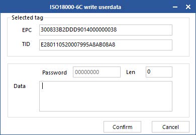
Figure 4.3.2 write user data
Select data (with TID information) of a read tag, fill in EPC data (hexadecimal character string), then click “Confirm”.
4.3.3 Custom Tag Operation
Select a tag data in the displaying data area before custom tag operation. Otherwise, the tag with the best signal will be the default one. Take care to follow the communication protocol about the writing/ reading/ locking/ destroying for the tag.
4.3.3.1 ISO18000-6C Tag
Select 6C as tag type. Click ![]() , and the dialog box will pop up, as shown in Figure 4.3.3.1. Writing operation can change data of the specified area of the tag. Access passwor is needed if such area is locked.
, and the dialog box will pop up, as shown in Figure 4.3.3.1. Writing operation can change data of the specified area of the tag. Access passwor is needed if such area is locked.

Figure 4.3.3.1 6C Tag Custom Operation(Write)
Locking operation to 6C tag. The interface is 6C as shown in Figure 4.3.3.2. Select the area for operation and corresponding operation, fill in password then the operation can be done, or it will fail (it also fails for tag without any password).

Figure 4.3.3.2 6C Tag Custom Operation( Lock)
Destroying operation to 6C tag is as shown in Figure 4.3.3.3. Click Destroy after filling in the password, then the tag will be destroyed. This operation is irrevocable and the tag destroyed will be invaid permanently.

Figure 4.3.3.3 6C Tag Custom Operation(Destroy)
4.3.3.2 ISO18000-6B Tag
Select 6B as tag type. Click ![]() , and the dialog box will pop up, as shown in Figure 4.3.3.4. Only user area is writable area for 6B tag. Click “Write” after filling in the start address and writing content.
, and the dialog box will pop up, as shown in Figure 4.3.3.4. Only user area is writable area for 6B tag. Click “Write” after filling in the start address and writing content.

Figure 4.3.3.4 6B Tag Custom Operation(Write)
The locking operation for 6B tag includes locking and locking get. As shown in Figure 4.3.3.5, fill in operation address, and click “Lock” to lock this address. The locked address is irreversible. Click “Get” to check if the adress is locked.
Notes: The locking for 6B tag is irrevocable and irreversibel. And The lock operation defined by this command is a single operation.

Figure 4.3.3.5 6B Tag Custom Operation(lock)
4.3.3.3 GB/T 29768―2013 Tag
Select GB as tag type. Click ![]() , and the dialog box will pop up, as shown in Figure 4.3.3.6. Select the writing area, fill iin the address and content, click “Write”, then the opertion is done with the Write successfully Prompt. Read the data after writing to check if the data writing is correct if needed.
, and the dialog box will pop up, as shown in Figure 4.3.3.6. Select the writing area, fill iin the address and content, click “Write”, then the opertion is done with the Write successfully Prompt. Read the data after writing to check if the data writing is correct if needed.

Figure 4.3.3.6 GB/T 29768―2013 Tag Custom Operation(Write)
The locking operation of national-standard tag is as shown in Figure 4.3.3.7. Select the area for operation and corresponding operation, fill in password then the operation can be done, or it will fail (it also fails for tag without any password).

Figure 4.3.3.7 GB/T 29768―2013 Tag Custom Operation(Lock)
Destroying operation to national-standard tag is as shown in Figure 4.3.3.8. Click Destroy after filling in the password, then the tag will be destroyed. This operation is irrevocable and the tag destroyed will be invaid permanently.

Figure 4.3.3.8 National-standard Tag Custom Operation(destroy)
4.4 Device Configuration
Select Device Control in the main interface of the Demo ->Device Configuration and then the dialog will pop up as shown in Figure 4.4 .

Figure 4.4 Device Configuration
4.4.1 RS232 Parameter
The COM parameter is on the top left corner as shown in Figure 4.4.1. Click “Get” to acquire the communication baud rate parameter of the COM. Then click Setting to set the communication baud rate parameter of the COM. Baud rate includes 9600 bps, 19200 bps, 115200 bps, 230400 bps and 460800bps, and the others are unsupported. The default one is 115200 bps.

Figure 4.4.1 COM Parameter
4.4.2 RS485 Parameter
The RS485 parameter is on the top left corner as shown in Figure 4.4.2. Click “Get” to acquire the communication baud rate parameter of the RS485. Then click Setting to set the communication baud rate parameter of the COM. Baud rate includes 9600 bps, 19200 bps, 115200 bps, 230400 bps and 460800bps. The default one is 115200 bps. The RS485 BUS address(0~255) is on the text box on the right.

Figure 4.4.2 RS485 parameter
4.4.3 Ethernet Parameter
The Ethernet parameter is on the lower left corner as shown in Figure 4.4.3.1. Click “Get” to check the Ethernet parameter of the reader, then click Setting to set the Ethernet parameter.
Click “Get” to check the Ethernet parameter after configuration(as shown in Figure 4.4.3.2) if Acquire IP Automatically is being used as shown in Figure 4.4.3.3. Connect the reader with TCP as shown in Figure 4.4.3.4,fill in IP address, click “Set”, then the prompt will pop up as shown in Figure 4.4.3.5. Acquire IP Automatically normally works with a router.

Figure 4.4.3.1 Ethernet parameter

Figure 4.4.3.2 Acquire IP Automatically

Figure 4.4.3.3 IP Parameter

Figure 4.4.3.4 TCP Connection

Figure 4.4.3.5 TCP Connect Success
4.4.4 Reader Time
The reader time is on the top right of the reader as shown in Figure 4.4.4.1. Click “Get” to acquire the time of the reader. The time is based on UTC and displayed according to the current time zone. Double click the text box to fill in the current system time automatically. Click setting to set the reader time as shown in Figure 4.4.4.2 .

Figure 4.4.4.1 Get the Reader Time

Figure 4.4.4.2 Reader Time Setting
4.4.5 Reader MAC
The MAC parameter is on the top right of the popup as shown in Figure 4.4.5. Click “Get” to acquire the MAC parameter of the reader.

Figure 4.4.5 Reader MAC
4.4.6 TCP Server/Client Mode
The TCP server/client mode parameter is on the lower right of the popup as shown in Figure 4.4.6.1. Click “Get” to acquire the TCP server/client mode parameter of the reader. If it is configured to be client mode, this IP should be fill in the IP of the user’s computer, then click Setting as shown in Figure 4.4.6.2. The default port is 8160.
Disconnect and go back to the main interface after setting, select Connect Device ->Tcp Server,then the tcp server interface will pop up as shown in Figure 4.4.6.3. Click Start Monitoring as shown in Figure 4.4.6.4, there will be prompt saying the connection is successful after a few seconds. Then click Stop Monitoring or close the popup directly.

Figure 4.4.6.1 TCP Server/Client Mode Parameter

Figure 4.4.6.2 Set TCP Server/Client Mode Parameter

Figure 4.4.6.3 TCP Client Mode

Figure 4.4.6.4 Monitoring Port

Figure 4.4.6.5 Connection success
4.5 GPI/O Configuration
Select Device Control in the main interface of the Demo->Device Configuration, and the dialog box will pop up. Select GPIO on the left of the popup and enter the GPIO controlling interface as shown in Figure 4.5 .

Figure 4.5 GPIO Configuration
4.5.1 GPO Configuration
GPO configuration is on the top left of the interface, through which the electrical level of the GPO can be configured as shown in Figure 4.5.1. The low electrical level will be on and high electrical level will be off, if it is connected with a relay. If it is connected with a optocoupler, the electrical levels remain unchanged.

Figure 4.5.1 GPO Configuration
4.5.2 GPI State Get
The GPI state is on the top right of the interface. Through which the GPI state can be queried as shown in Figure 4.5.2.

Figure 4.5.2 GPI State Get
4.5.3 GPI Operation Configuration
The GPI operation is on the lower right of the interface. Select a GPI port number, and click “Get” to check the related configuration of the port as shown in Figure 4.5.3.1. There are multiple conditions optional for trigger condition and Stop condition. Trigger instructions can be written according to communication protocols or extract directly from logs with the following methods:
1. Suppose that a port (GPI1) need to be configured to read the TID of the 6C tag after triggering. Operations are detailed in Read TID, as shown in Figure 4.5.3.2 and Figure 4.5.3.3 ;
2. Click ![]()
on the left to switch and an interface as shown in Figure 4.5.3.4 will be seen ;
3. Find data with “send-[MsgBaseInventoryEpc]-[5A000102100008000000010102
0006ED08]” in the log interface and extract” 5A0001021000080000000101020006ED
08” from it ;
4. Remove the 2-digit frame header and 4-digit check code in the end. 0001021000080000000101020006 is the TID command for tag reading. Other command can be also acquired with the same operation ;
5. Open GPIO interface, select GPI 1 get as shown in Figure 4.5.3.1. Select trigger condition and stop condition, fill the command from step 4 in the trigger command, then click Configure as shown in Figure 4.5.3.4. When the configuration is successful, the reader reads the TID operation of 6C tag when the electrical level of GPI1 port is high and stop reading when the electrical level is low .
When the stop condition is “delay stop”, the specific delay time can be filled in at delay time area (0 means infinite delay time). And the unit is 10ms. The reader will stop after corresponding period when the stop condition is triggered if the configuration is done.

Figure 4.5.3.1 GPI Operation Get

Figure 4.5.3.2 Main Interface

Figure 4.5.3.3 Read TID of 6C tag

Figure 4.5.3.3 Log

Figure 4.5.3.4 GPI Operation Configuration
4.6 RFID Configuration
Select Device Control in the main interface of the Demo-> RFID Configuration and the dialog will pop up as shown in Figure 4.6 .

Figure 4.6 RFID Configuration
4.6.1 EPC Baseband Parameter
The EPC baseband parameter is on the top left as shown in Figure 4.6.1. Click “Get” to acquire the EPC baseband parameter. And click Setting to set the EPC baseband parameter.

Figure 4.6.1 Baseband Parameter Configuration
R/W effect changes with the changing of the baseband parameter configuration (the configuration can be customized according to the real application, but under the guidance of our engineer).
There are 6 choices for EPC baseband rate: Tair=25us, FM0, LHF=40KHz; dense reading mode; Tair=25us, Miller4, LHF=300KHz; fast reading mode; Tari=25us, Miller4, LHF=320KHz; 255/AUTO . 4 choices for Session:0 ; 1 ; 2 ; 3 .
16 choices for Q value:0/single tag; 1; 2; 3; 4/multiple tag; 5; 6; 7; 8; 9; 10; 11; 12; 13; 14; 15 .
3 choices for tag searching: A side inventory-taking; B side inventory-taking; A|B double sides inventory-taking .
4.6.2 Power Configuration for Antenna Port
The antenna port is on the lower left as shown in Figure 4.6.2. Click “Get” to acquire the antenna power. And click Setting to set the antenna power.

Figure 4.6.2 Power Configuration for Antenna Port
Select the corresponding antenna port(connected with antenna), and select corresponding power value from the power list. Then click Set, and the Configured Successfully prompt will pop up.
4.6.3 Auto-idleness Configuration
Automatic idle mode means: when in constantly reading, the reader will enter idle state automatically for power saving for a period if no tag is read for 3 round constantly. When the idle state is over time, the reader will start reading again as shown in Figure 4.6.3.

Figure 4.6.3 Automatic Idleness Configuration
4.6.4 Tag Filtering
The antenna power is on the lower left as shown in Figure 4.6.4. Click “Get” to acquire the tag uploading parameter. And click Setting to set the tag uploading parameter.
Filtering Time: means during a reading instruction execution period, the same tag content can only be uploaded once in repeated tag filtering time, 0~65535,the time unit is 10ms.
RSSI threshold value:give up uploading and discard when the RSSI value of the tag is lower than the threshold value.

Figure 4.6.4 Tag Filtering
4.6.5 Hopping Frequency Management


Figure 4.6.5.1 Hopping Frequency Management

Figure 4.6.5.2 Working Frequency Range Selection

Figure 4.6.5.3 Hopping Frequency Switch Selection

Figure 4.6.5.4 Frequency Selection
Notes: When doing this setting, the purpose of the automatic operations is to avoid the external signal interference. Normally it is defaulted to be automatically(as shown in the spinner of Figure 4.6.5.3).
4.7 Other Configurations
4.7.1 Wiegand Communication Parameter Configuration
Select Device Control in the main interface of the Demo->Device Configuration, and the dialog box will pop up. Select GPIO on the left popup. The Wiegand Configuration is at the lower left. Click “Get” to check the Wiegand communication parameter of the current device as shown in Figure 4.7.1.1.
There are 3 types of Wiegand communication: Wiegand 26, Wiegand 34 and Wiegand 66. Reader extracts the end data of EPC code or TID code according to Wiegand communication format and outputs it through Wiegand signal. It extracts 3 bytes at the end for Wiegand 26 , 4 bytes for Wiegand 34 format and 8 bytes for Wiegand 66 format. There are 2 types for data transfer: Transfer EPC end data and transfer TID end data. Click Set after selecting corresponding parameters as shown in Figure 4.7.1.2.

Figure 4.7.1.1 Wiegand Communication Parameter Get

Figure 4.7.1.2 Wiegand Communication Parameter Configuration
4.7.2 Buzzer Control
Select Device Control in the main interface of the Demo->Device Configuration, and the dialog box will pop up. Select GPIO in the popup on the left. The Buzzer Control is on the lower left. Click Set to set the state of the buzzer as shown in Figure 4.7.2.

Figure 4.7.2 Buzzer Control
4.7.3 EAS Alarm
Select Device Control in the main interface of the Demo -> Device Configuration, and the dialog box will pop up. Select Custom-1 in the popup on the left as shown in Figure 4.7.3. This operation is used for configuration for matching alarm parameters. “matching succeeded operation” will be performed when the tags meet the matching condition is read. And “match failed operation” will be performed when the tags fail to meet the matching condition is read. The matching rules are as below:
The calculated result of the mask Bitwise AND and zone data to be matched in the tag is A. And the result of the mask Bitwise AND and zone data matched is B. If A is equal to B, then the matching is successfully, and then the EAS match-successfully operation shall be performed. Conversely, the EAS match-failed operation shall be performed.

Figure 4.7.3 EAS Alarm
4.8 Tools
4.8.1 Restart
Select Tools ->“ ![]() ”Restart as shown in Figure 4.8.1.1. Click the icon, and the Command Sent Successfully prompt will pop up as shown in Figure 4.8.1.2.
”Restart as shown in Figure 4.8.1.1. Click the icon, and the Command Sent Successfully prompt will pop up as shown in Figure 4.8.1.2.
The reader will restart when it receives this message. And the restart is finished when the beep from the buzzer is heard.

Figure 4.8.1.1 Restart

Figure 4.8.1.2 Command Sent Successfully
4.8.2 Restore Factory Setting
Select Tools in the main interface ->“ ![]() ”Factory Reset as shown in Figure 4.8.2.1. Click the icon, and the prompt “Factory Reset?” will pop up as shown in Figure 4.8.2.2. This operation will restore all parameters, including RFID configuration parameters, to factory setting except for system time and MAC address.
”Factory Reset as shown in Figure 4.8.2.1. Click the icon, and the prompt “Factory Reset?” will pop up as shown in Figure 4.8.2.2. This operation will restore all parameters, including RFID configuration parameters, to factory setting except for system time and MAC address.

Figure 4.8.2.1 Factory Reset

Figure 4.8.2.2 Prompt
4.8.3 Data Export

Figure 4.8.3 Data Export
The tag data supports data export and the exporting format can be .csv and .xls(Excel datasheet).
4.8.4 Upgrade


Figure 4.8.4.1 upgrade baseband

Figure 4.8.4.2 Select Upgrade Files

Figure 4.8.4.3 Upgrading baseband

Figure 4.8.4.4 Restart Confirm
The upgrading process of baseband software is the same as the application software. And the detail operation is the same also.
4.8.5 Custom Command
Select Tools ->“ ![]() ” Custom Command as shown in Figure 4.8.5.1. Click the icon, and a custom command sending popup will come out as shown in Figure 4.8.5.2.
” Custom Command as shown in Figure 4.8.5.1. Click the icon, and a custom command sending popup will come out as shown in Figure 4.8.5.2.
Head: data frame header, defaulted to be 5A
Command: can be written according to the communication protocol of the reader, or extract by double clicking lines of the log window (detailed in GPI Operation Configuration)
CRC: check code(automatically generated by filling in command and head and clicking the CRC text box).

Figure 4.8.5.1 Custom Command

Figure 4.8.5.2 Custom Command Sending

Figure 4.8.5.3 Send Custom Command
4.8.6 Device Info

Figure 4.8.6.1 Device Info

Figure 4.8.6.2 Device Info Popup
4.8.7 Devices Search
Select Device searching in the main interface of the Demo -> ![]() Device Search (as shown in Figure 4.8.7.1) and then a dialog box will pop up as shown in Figure 4.8.7.2. Open the popup, and the reader will start searching the devices with the same network segment as the computer. And the devices will be in the list as shown in Figure 4.8.7.3.
Device Search (as shown in Figure 4.8.7.1) and then a dialog box will pop up as shown in Figure 4.8.7.2. Open the popup, and the reader will start searching the devices with the same network segment as the computer. And the devices will be in the list as shown in Figure 4.8.7.3.
Notes: This function is also workable when the demo is not connected with any device.

Figure 4.8.7.1 Network Devices Searching

Figure 4.8.7.2 Searching Devices

Figure 4.8.7.3 Searching Devices Successfully
FCC WARNING
This device complies with part 15 of the FCC Rules. Operation is subject to the following two conditions: (1) this device may not cause harmful interference, and (2) this device must accept any interference received, including interference that may cause undesired operation.
Any changes or modifications not expressly approved by the party responsible for compliance could void the user’s authority to operate the equipment.
NOTE: This equipment has been tested and found to comply with the limits for a Class B digital device, pursuant to Part 15 of the FCC Rules. These limits are designed to provide reasonable protection against harmful interference in a residential installation. This equipment generates, uses and can radiate radio frequency energy and, if not installed and used in accordance with the instructions, may cause harmful interference to radio communications.
However, there is no guarantee that interference will not occur in a particular installation. If this equipment does cause harmful interference to radio or television reception,
which can be determined by turning the equipment off and on, the user is encouraged to try to correct the interference by one or more of the following measures:
- Reorient or relocate the receiving antenna.
- Increase the separation between the equipment and receiver.
- Connect the equipment into an outlet on a circuit different from that to which the receiver is connected.
- Consult the dealer or an experienced radio/TV technician for help.
To maintain compliance with FCC’s RF Exposure guidelines, This equipment should be installed and operated with minimum 20cm distance between the radiator and your body: Use only the supplied antenna.
Read More About This Manual & Download PDF:
Documents / Resources
 |
RFID RF-N8204 UHF Reader [pdf] Instruction Manual RF-N8204 UHF Reader, RF-N8204, UHF Reader, Reader |