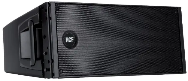
RCF HDL20-A Active 2 Way Dual 10 Line Array Module
SAFETY PRECAUTIONS
- All the precautions, in particular the safety ones, must be read with special attention, as they provide important information.
WARNING: to prevent the risk of fire or electric shock, never expose this product to rain or humidity. - POWER SUPPLY FROM MAINS
- The mains voltage is sufficiently high to involve a risk of electrocution; install and connect this product before plugging it in.
- Before powering up, make sure that all the connections have been made correctly and the voltage of your mains corresponds to the voltage shown on the rating plate on the unit, if not, please contact your RCF dealer.
- This unit is CLASS I construction, so it must be connected to a MAIN socket outlet with a protective earthing connection.
- Appliance coupler or PowerCon Connector® is used to disconnect device from MAIN power. This device shall remain readily accessible after the installation
- Protect the power cable from damage; make sure it is positioned in a way that it cannot be stepped on or crushed by objects.
- To prevent the risk of electric shock, never open this product: there are no parts inside that the user needs to access.
- Make sure that no objects or liquids can get into this product, as this may cause a short circuit.
This apparatus shall not be exposed to dripping or splashing. No objects filled with liquid, such as vases, shall be placed on this apparatus. No naked sources (such as lighted candles) should be placed on this apparatus. - Never attempt to carry out any operations, modifications or repairs that are not expressly described in this manual.
Contact your authorized service centre or qualified personnel should any of the following occur:- The product does not function (or functions in an anomalous way).
- The power cable has been damaged.
- Objects or liquids have got in the unit.
- The product has been subject to a heavy impact.
- If this product is not used for a long period, disconnect the power cable.
- If this product begins emitting any strange odours or smoke, switch it off immediately and disconnect the power cable.
- Do not connect this product to any equipment or accessories not foreseen.
For suspended installation, only use the dedicated anchoring points and do not try to hang this product by using elements that are unsuitable or not specific for this purpose. Also check the suitability of the support surface to which the product is anchored (wall, ceiling, structure, etc.), and the components used for attachment (screw anchors, screws, brackets not supplied by RCF etc.), which must guarantee the security of the system / installation over time, also considering, for example, the mechanical vibrations normally generated by transducers.
To prevent the risk of falling equipment, do not stack multiple units of this product unless this possibility is specified in the user manual. - RCF S.p.A. strongly recommends this product is only installed by professional qualified installers (or specialised firms) who can ensure correct installation and certify it according to the regulations in force.
The entire audio system must comply with the current standards and regulations regarding electrical systems. - Supports and trolleys
The equipment should be only used on trolleys or supports, where necessary, that are recommended by the manufacturer. The equipment / support / trolley assembly must be moved with extreme caution. Sudden stops, excessive pushing force and uneven floors may cause the assembly to overturn. - There are numerous mechanical and electrical factors to be considered when installing a professional audio system (in addition to those which are strictly acoustic, such as sound pressure, angles of coverage, frequency response, etc.).
- Hearing loss
Exposure to high sound levels can cause permanent hearing loss. The acoustic pressure level that leads to hearing loss is different from person to person and depends on the duration of exposure. To prevent potentially dangerous exposure to high levels of acoustic pressure, anyone who is exposed to these levels should use adequate protection devices. When a transducer capable of producing high sound levels is being used, it is therefore necessary to wear ear plugs or protective earphones. See the manual technical specifications to know the maximum sound pressure level.
IMPORTANT NOTES
To prevent the occurrence of noise on line signal cables, use screened cables only and avoid putting them close to:
- Equipment that produces high-intensity electromagnetic fields.
- Power cables.
- Loudspeaker lines.
The equipments considered in this manual can be used in electromagnetic environment E1 to E3 as specified on EN 55103-1/2: 2009.
OPERATING PRECAUTIONS
- Place this product far from any heat sources and always ensure an adequate air circulation around it.
- Do not overload this product for a long time.
- Never force the control elements (keys, knobs, etc.).
- Do not use solvents, alcohol, benzene or other volatile substances for cleaning the external parts of this product.
IMPORTANT NOTES
Before connecting and using this product, please read this instruction manual carefully and keep it on hand for future reference. The manual is to be considered an integral part of this product and must accompany it when it changes ownership as a reference for correct installation and use as well as for the safety precautions. RCF S.p.A. will not assume any responsibility for the incorrect installation and / or use of this product.
CAUTION: to prevent electric shock hazard, do not connect to mains power supply while grille is removed
PRODUCT INFORMATIONS
- The concept of this unique speaker derives from the touring industry, bringing in a compact cabinet all the experience of RCF professional sound.
- The vocals are natural, the sound is clear at longer distances, the spl power is stable at very high levels.
- The RCF Precision transducers equipping D LINE have been representing for decades the ultimate performance, the highest power handling and the mos advanced technology in the professional and touring industry.
- The high power woofer delivers extremely accurate punchy bass, the custom made compression driver offers a transparent midrange and extreme fidelity.
- RCF Class-D power amplifiers technology packs huge performance operating with high efficiency into a lightweight solution. D LINE amplifiers deliver ultra fast attack, realistic transient response and impressive audio performance.
- The integrated DSP manages crossover, equalisation , soft limiter, compressor and dynamic bass boost. D LINE cabinets are moulded on a special polypropylene composite material designed to dampen down vibrations even at maximum volume settings.
- From moulding to the final texture, D LINE offers the maximum reliability and strength for the intensive use on the road.
- The HDL20-A and HDL10-A are very compact, self-powered, 2-way line array loudspeaker modules. The 700-watt Class-D amp modules accurately match the high quality digital signal input boards with precise, complex filter responses that result in the natural, detailed reproduction of the best direct radiating designs. They are the ideal choice when line-array performance is needed but the venue size doesn’t call for the very long-throw characteristics of larger line-arrays and a fast and easy setup is a must. The speakers deliver extraordinary power handling, clarity, flexibility and great sound in a compact, easy to handle and affordable package.
THE INPUT SECTION PROVIDES:
- Out XLR connectors;
- IN XLR Jack combo
- system volume control;
- 5 configuration switch;
- 4 status LEDs.
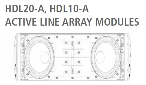
HDL20-A IS A 2-WAY ACTIVE SYSTEM FEATURING:
- 10” neo woofer, 2,5” voice coil in horn loaded configuration;
- 2” exit, 3” voice coil neo compression driver;
- 100° x 15°, constant directivity coverage angle.
HDL10-A IS A 2-WAY ACTIVE SYSTEM FEATURING:
- 8” neo woofer, 2,0” voice coil in horn loaded configuration;
- 2” exit, 2,5” voice coil neo compression driver;
- 100° x 15°, constant directivity coverage angle.
THE AMPLIFIER SECTION FEATURES:
- 700 Watt switching power supply module;
- 500 Watt low frequency digital amplifier module;
- 200 Watt high frequency digital amplifier module;
- extra capacitor bus able to sustain the voltage for 100 ms burst signals.
The total available power supply power is 700 Watt and can be distributed to the 2 final amplifier sections. Each amplifier section has a very high maximum output power capability in order to provide, when necessary, maximum output bursts in a specific frequency range.
POWER REQUIREMENTS AND SET-UP
The HDL line arrays Systems are designed to operate in hostile and demanding situations. Nevertheless it is important to take extremely care of the AC power supply and set up a proper power distribution. The HDL line arrays Systems are designed to be GROUNDED. Always use a grounded connection.
The HDL amplifiers are designed to work within the following AC Voltage limits:
- 230 V NOMINAL VOLTAGE: minimum voltage 185 V, maximum voltage 260 V
- 115 V NOMINAL VOLTAGE: minimum voltage 95 V, maximum voltage 132 V.
If the voltage goes below the minimum admitted voltage the system stops working If the voltage goes higher than the maximum admitted voltage the system can be seriously damaged. To obtain the best performances from the system it is very important that the voltage drop it is as low as possible. Make sure that all the system is properly grounded. All the grounding points shall be connected to the same ground node. This will improve reducing hums in the audio system.
The module is provided with a Powercon outlet to daisy chain other modules. The maximum number of modules that is possible to daisy chain is:
16 (SIXTEEN) OR 4 HDL 18-AS + 8 HDL 20-A MAXIMUM OR 8 HDL18-A. 230 Volt NOMINAL VOLTAGE: minimum voltage 185 Volt, maximum voltage 264 Volt (for UK 240V+10%) 115 Volt NOMINAL VOLTAGE: minimum voltage 95 Volt, maximum voltage 132 Volt.
A superior number of modules in daisy chain will exceed the Powercon connector maximum ratings and create a potentially dangerous situation. When the HDL line arrays systems are powered from a three phase power distribution it is very important to keep a good balance in the load of each phase of the AC power. It is very important to include subwoofers and satellites in power distribution calculation: both subwoofers and satellites shall be distributed between the three phases.
GROUNDING 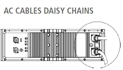
WARNING
POWERING FROM THREE PHASE
REAR PANEL
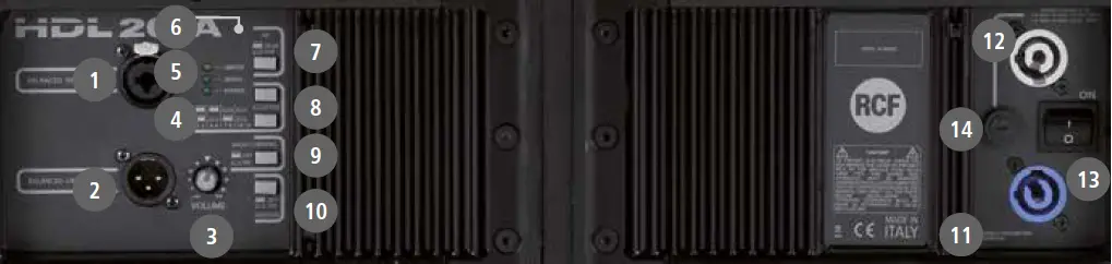
- MAIN XLR INPUT (BAL/UNBAL).The system accept male XLR/Jack input connectors with line level signals from a mixing console or other signal source.
- LINK XLR OUTPUT. The output XLR male connector provides a loop trough for speakers daisy chaining.
- VOLUME. Controls the volume of the power amplifier. The control ranges from – (maximum attenuation) to the MAX level ∞ (maximum output).
- POWER INDICATOR. Power on indicator. When the power cord is connected and the power switch is turned on this indicator lights green.
- SIGNAL INDICATOR. The signal indicator lights green if there is signal present on the main XLR input.
- LIMITER INDICATOR. The amplifier has a built in limiter circuit to prevent clipping of the amplifiers or overdriving the transducers. When the peak clipping circuit is active the LED blinks orange. It is okay if the limit LED blinks occasionally. If the LED blinks frequently or lights continuously, turn down the signal level. The amplifier has a built in RMS limiter. If the RMS limiter is active the LED lights red. The RMS limiter has the purpose to prevent damages the transducers. The speaker shall never be used with the limit indicator red, continuous operation with the RMS protection active can cause damages to the speaker.
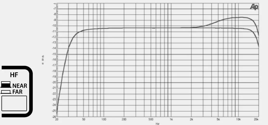
- HF. The switch gives the possibility to set high frequencies correction depending on target distance (air absorption correction):
- NEAR (used for pole mount applications or near field)
- FAR (for farthest field).
- CLUSTER. The combination of the 2 switches gives 4 possibilities of mid low frequencies correction depending on cluster size.
- 2-3 modules (used for pole mount applications ground stacking)
- 4-6 modules (small flown systems)
- 7-9 modules (medium flown systems)
- 10-16 modules (maximum flown configuration).
- HIGH CURVING. The switch gives the extra possibility to boost mid frequencies depending on a high curving cluster configuration of few pieces.
- OFF (not active correction)
- ON (for high curving arrays of few pieces HDL20-A or HDL10-A).
- INDOOR. The switch gives the extra possibility to set low frequencies correction depending on a indoor/outdoor use, in order to compensate room reverberation on lows.
- OFF (not active correction)
- ON (correction for reverberant indoor rooms).
AC POWERCON RECEPTACLE. RCF D LINE uses a POWERCON locking 3-pole AC mains. Always use the specific power cord provided in the package.
- AC POWERCON LINK RECEPTACLE. Use this receptacle to link one or more units. Always make sure that the maximum current requirement does not
exceed the maximum admitted POWERCON current. In case of doubt call the closest RCF SERVICE CENTRE. - INDOOR. The switch gives the extra possibility to set low frequencies correction depending on a indoor/outdoor use, in order to compensate room reverberation on lows.
- OFF (not active correction)
- ON (correction for reverberant indoor rooms).
- POWER MAIN SWITCH. The power switch turns the AC power ON and OFF. Make sure that the VOLUME is set to – when you turn on the speaker.
- FUSE.
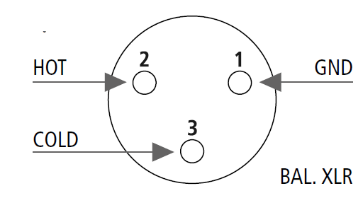
The XLR connectors use the following AES standard:- PIN 1 = GROUND (SHIELD)
- PIN 2 = HOT (+)
- PIN 3 = COLD (-)
At this point you can connect the power supply cable and the signal cable, but before turning on the speaker make sure that the volume control is at the minimum level (even on the mixer output). It is important that the mixer is already ON before turning on the speaker. This will avoid damage to the speakers and noisy “bumps” due to turning on parts on the audio chain. It is a good practice to always turn on speakers at last and turn them off immediately after the show. Now you can turn ON the speaker and adjust the volume control to a proper level.
WARNING: Always make sure that the maximum current requirement does not exceed the maximum admitted POWERCON current. In case of doubt call the closest RCF SERVICE CENTRE.
- 230 Volt, 50 Hz SETUP: FUSE VALUE T3,15A – 250V
- 115 Volt, 60 Hz SETUP: FUSE VALUE T6, 30A – 250V
Audio signal can be daisy-chained using the male XLR loop through connectors. A single audio source can drive multiple speakers modules (like a full left or right channel made of 8-16 speaker modules); make sure that the source device is able to drive the impedance load made of the modules input circuits in parallel.The HDL line arrays input circuit presents a 100 KOhm input impedance. The total input impedance seen as a load from the audio source (ex. audio mixer) will be:
- system input impedance = 100 KOhm / number of input circuits in parallel.
The required output impedance of the audio source (ex. audio mixer) will be:
- source output impedance > 10 * system input impedance;
- always make sure that XLR cables used to feed audio signal to the system are:
- balanced audio cables;
- wired in phase.
A single defective cable can affect the performance of the overall system!
BEFORE TURNING ON THE SPEAKER
WARNING
VOLTAGE SETUP
(RESERVED TO THE RCF SERVICE CENTRE)
SIGNAL CABLES DAISY CHAINS
SINGLE HDL20-A, HDL10-A
The HDL is a flexible system that can be used in ground-supported or suspended applications. The following information will help you set up your HDL system safely and effectively.
When using stands or poles, be sure to observe the following precautions:
- Check the stand or pole specification to be certain the device is designed to support the weight of the speaker. Observe all safety precautions specified by the manufacturer.
- Be certain that the surface on which the system is to be stacked is flat, stable and solid.
- Inspect the stand (or pole and associated hardware) before each use and do not use equipment with worn, damaged, or missing parts.
- Do not attempt to place more than two HDL loudspeakers on a stand or pole.
- When mounting two HDL speakers on a pole or tripod, integral rigging hardware must be used to secure the speakers to each other.
- Always be cautious when deploying the system outdoors. Unexpected winds may topple a system. Avoid attaching banners or similar items to any part of a speaker system. Such attachments could act as a sail and topple the system.
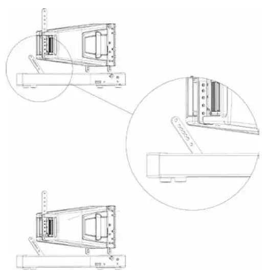
A single HDL may be used on a tripod stand (AC S260) or on a pole (AC PMA) over its D LINE Series subwoofers. The use of a subwoofer is recommended for applications requiring more low-frequency power and extension and needs a pole (P.N. 13360110).
Usually, the cluster switch on the input panel should be set to the 2-3 position and the HF on NEAR when a single speaker is used. Indoor switch use depends on the speaker placement. Place the speaker on the pole or on a tripod using its own hardware LIGHT BAR HDL20-A (P.N. 13360229) or LIGHT BAR HDL10-A (P.N. 13360276) as shown in the following picture.
POLE AND TRIPOD SAFETY WARNINGS 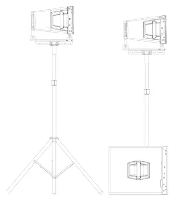
BEFORE INSTALLATION – SAFETY – PARTS INSPECTION
- Since this product has been designed to be lifted above objects and people, it is essential to dedicate particular care and attention to the inspection of the product’s mechanics, accessories and safety devices in order to guarantee maximum reliability during use.
- Before lifting the Line Array, carefully examine all mechanics involved in lifting including hooks, quick lock pins, chains and anchor points. Make sure they are intact, with no missing parts, fully functional, with no signs of damage, excessive wear or corrosion that could compromise safety during use.
- Verify that all accessories supplied are compatible with the Line Array and that they are installed correctly according to the instructions provided in the manual. Make sure they perform their function perfectly and are able to support the weight of the device safely.
- If you have any doubts about the safety of the lifting mechanisms or accessories, do not lift the Line Array and contact our service department immediately. The use of a damaged device or with unsuitable accessories can cause serious injury to you or other people.
- When inspecting the mechanics and accessories, pay maximum attention to every detail, this will help ensure safe and accident-free use.
- Before lifting the system, have all parts and components inspected by trained and experienced personnel.
- Our company is not responsible for incorrect use of this product caused by failure to comply with inspection and maintenance procedures or any other failure.
INSPECTION OF MECHANICS, ACCESSORIES AND LINE ARRAY SAFETY DEVICES 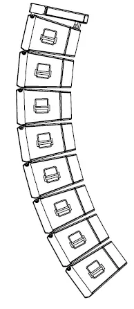
- Visually inspect all mechanics to ensure there are no desoldered or bent parts, cracks or corrosion.
- Inspect all the holes on the mechanics; check that they are not deformed and that there are no cracks or corrosion.
- Check all cotter pins and shackles and make sure they perform their function correctly; replace these components if it is not possible to fit them and lock them correctly on the fixing points.
- Inspect any lifting chains and cables; check that there are no deformations, corroded or damaged parts.
- Check that the pins are intact and have no deformities
- Test the operation of the pin making sure the button and spring work properly
- Check the presence of both spheres; make sure they are in their correct position and that they retract and exit correctly when the button is pressed and released.
INSPECTION OF MECHANICAL ELEMENTS AND ACCESSORIES
INSPECTION OF QUICK LOCK PINS
- Suspending loads should be done with extreme caution.
- When deploying a system always wear protective helmets and footwear.
- Never allow people to pass under the system during the installation process.
- Never leave the system unattended during the installation process.
- Never install the system over areas of public access.
- Never attach other loads to the array system.
- Never climb the system during or after the installation.
- Never expose the system to extra loads created from the wind or snow.
WARNING: The system must be rigged in accordance with the laws and regulations of the Country where the system is used. It is responsibility of the owner or rigger to make sure that the system is properly rigged in accordance with Country and local laws and regulations.
WARNING: Always check that all the parts of the rigging system that are not provided from RCF are:
- appropriate for the application;
- approved, certified and marked;
- properly rated;
- in perfect condition.
WARNING: Each cabinet support the full load of the part of the system below. It is very important that each single cabinet of the system is properly checked.
- The suspension system is designed to have a proper Safety Factors (configuration dependent). Using the “RCF Shape Designer” software it is very easy to understand safety factors and limits for each specific configuration. To better comprehend in which safety range the mechanics are working a simple introduction is needed: HDL mechanics are built with certified UNI EN 10025-95 S 235 JR and S 355 JR Steel.
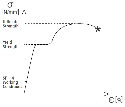
- S 235 JR is a structural steel and has a stress-strain (or equivalent Force-Deformation) curve like the following.
- The curve is characterized by two critical points: the Break Point and the Yield Point. The tensile ultimate stress is simply the maximum stress attained. Ultimate tensile stress is commonly used as a criterion of the strength of the material for structural design, but it should be recognized that other strength properties may often be more important. One of these is for sure the Yield Strength. Stress-strain diagram of S 235 JR exhibit a sharp break at a stress below the ultimate strength. At this critical stress, the material elongates considerably with no apparent change in stress. The stress at which this occurs is referred to as the yield point.
- Permanent deformation may be detrimental, and the industry adopted 0.2% plastic strain as an arbitrary limit that is considered acceptable by all regulatory agencies. For tension and compression, the corresponding stress at this offset strain is defined as the yield.
- S 355 J and S 235 JR characteristic values are R=360 [N/mm2] and R=510 [N/mm2] for Ultimate Strength and Rp0.2=235 [N/mm2] and Rp0.2=355 [N/mm2] for Yield Strength. In our prediction software the Safety Factors are calculated considering the Maximum Stress Limit equal to the Yield Strength, according with many international standards and rules. The resulting Safety Factor is the minimum of all the calculated safety factors, for each link or pin. This is where you are working with a SF=4:
Depending on local safety regulation and on situation the required safety factor can vary. It is responsibility of the owner or rigger to make sure that the system is properly rigged in accordance with Country and local laws and regulations. The “RCF Shape Designer” software gives detailed information of the safety factor for each specific configuration. The safety factor is the result of the forces acting on fly bar’s and system’s front and rear links and pins and depends on many variables:
- number of cabinets;
WARNING
“RCF SHAPE DESIGNER” SOFTWARE AND SAFETY FACTOR 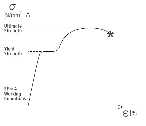
- fly bar angles;
- angles from cabinets to cabinets. If one of the cited variables change the safety factor MUST BE recalculated using the software before rigging the system.
In case the fly bar is picked up from 2 motors make sure that the fly bar angle is correct. An angle different from the angle used in the prediction software can be potentially dangerous. Never allow persons to stay or pass under the system during the installation process. When the fly bar is particularly tilted or the array is very curved the centre of gravity can move out from the rear links. In this case the front links are in compression and the rear links are supporting the total weight of the system plus the front compression. Always check very carefully with the “RCF Shape Designer” software all this kind of situations (even with a small number of cabinets).
THE MAXIMUM NUMBER OF SPEAKERS THAT MAY BE SUSPENDED USING
THE HDL20-A FRAME IS:
- n° 16 HDL20-A;
- n° 8 HDL18-AS;
- n° 4 HDL 18-AS + 8 (EIGHT) HDL 20-A USING ACCESSORY LINK BAR HDL20-HDL18-AS
THE MAXIMUM NUMBER OF SPEAKERS THAT MAY BE SUSPENDED USING
THE HDL10-A FRAME IS:
- n° 16 HDL10-A;
- n° 8 HDL15-AS;
- n° 4 HDL 15-AS + 8 (EIGHT) HDL 10-A USING ACCESSORY LINK BAR HDL10-HDL15-AS
MAXIMUM ARRAY SIZE
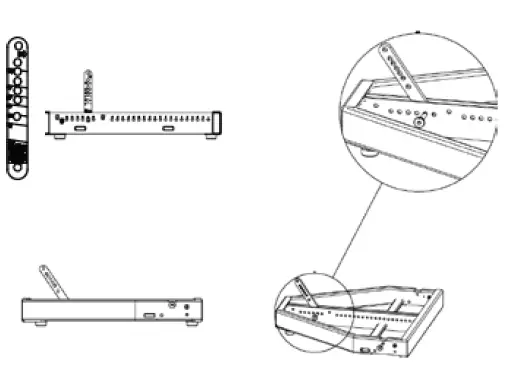
THE HDL FLY BAR
- FRONT FLYING BRACKET. Front mounting.
- QUICK LOCK PIN HOLE. Front mounting (to be used to lock the front bracket before installation).
- FRONT BRACKET – TRANSPORT HOLES.
- CENTRAL PICK UP POINTS.
- The pickup point is asymmetric and can be fit in two positions (A and B).
A position brings the shackle towards the front.
B position allows an intermediate step using the same fixing holes. - Move the pickup bracket in the position suggested by RCF Shape Designer.
- Fix the pickup bracket with the two pins on the bracket’s lanyard to lock the pickup.
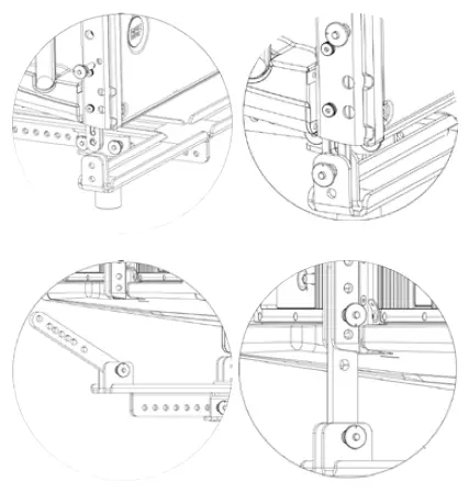
THE HDL FLY BAR FEATURES: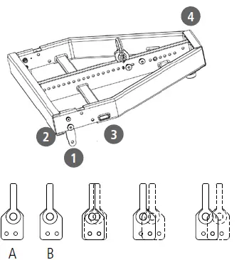
 Check that all the pins are secured and locked.
Rigging the system follow the procedure:- RIGGING CHAIN HOIST.
- CERTIFIED SHACKLE.
- FLY BAR.
RIGGING PROCEDURE
- Connect the fly-bar F to the chain hoist H (o motors) using the certified shackle. Secure the shackle.
- Connect the second pin on the front bracket to make sure that the connecting bracket is vertical.
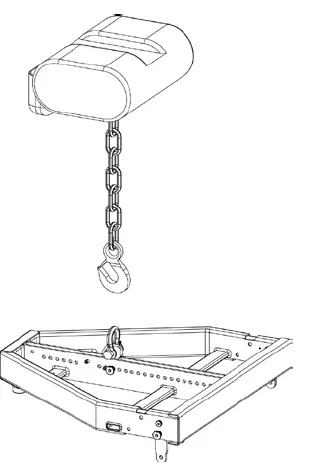
- Connect the front bracket to the first HD cabinet using 2 quick lock pins.
USING THE FLY BAR HDL 20 LIGHT (P.N. 13360229) IT IS ALLOWED TO CONNECT A MAXIMUM OF 4 HDL 20-A MODULES.
USING THE FLY BAR HDL 10 LIGHT (P.N. 13360276) IT IS ALLOWED TO CONNECT A MAXIMUM OF 6 HDL 10-A MODULES.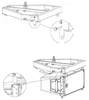
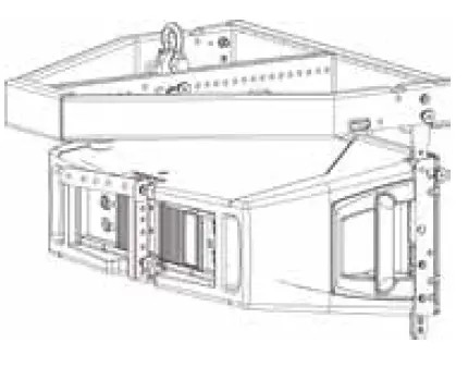
- Reverse and connect the 1 rear bracket to the fly-bar using 2 quick lock pins.
The first HDL has to be fixed always starting at 0° with respect of the frame. No other angles are allowded.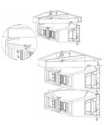
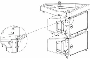
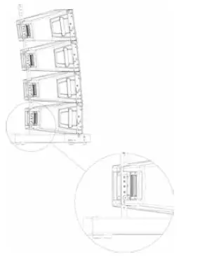
- Connect the second cabinet to the first always starting from the 2 front brackets.
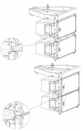
- Reverse and connect the rear bracket of the second cabinet using the hole for the proper angle.
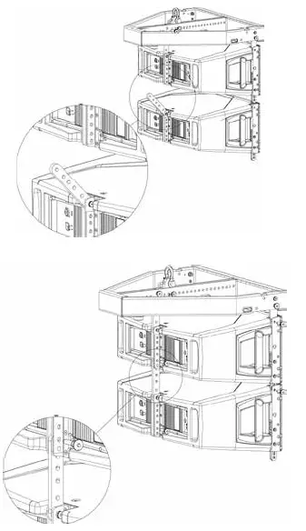
- Connect all the other cabinets following the same procedure and connecting a single cabinet each time.
ARRAY SYSTEMS DESIGN
HDL allow users to choose from different face-to-face angle adjustments to create arrays with varying curvature. Thus, designers can create arrays custom-tailored to each venue’s profile.
The basic approach to array design dependent on three factors:
- Number of Array Elements;
- Vertical Splay Angles;
- Horizontal Coverage.
Determining the number of elements to use is critical: the number of elements greatly affects the SPL available from the system as well as the uniformity of coverage in both SPL and frequency response. The number of elements profoundly effects the directivity at lower frequencies. The next easy equation, works as an approximation for flat listening planes. Coverage (x) ≈ 8n (m) Coverage distance required = x (metres).
Changing the splay angles between cabinets has a significant impact on vertical coverage for the high frequencies, with the result that narrower vertical splay angles produce a higher Q vertical beamwidth, while wider splay lowers the Q at high frequencies. In general, the splay angles do not affect the vertical coverage at lower frequencies.
The curved array system design can be summarized as:
- flat-front HDL for long throw sections;
- increase curvature as distance decreases;
- add more enclosures for more output.
This approach focuses more transducers mounted on long-throw horns at the farthest seat, gradually focusing fewer transducers as distance decreases. As long as the no gap rule is maintained, arrays constructed according to these principles will provide even SPL and a consistent sonic character throughout the venue without requiring complex processing. This approach, where the same amount of acoustic energy is spread over a larger or smaller vertical angle depending on required throw, typically have the following objectives:
- even horizontal and vertical coverage;
- uniform SPL;
- uniform frequency response;
- sufficient SPL for the application.
This discussion represents, of course, just a basic approach. Given the infinite variety of venues and performers, users will find themselves needing to solve specific problems in specific situations. RCF Shape Designer software designed to help calculate optimum splay angles, aiming angles, and fly-bar pick points (crucial in aiming the array) for a given venue, will be explained later in this Guide.
SOFTWARE EASY SHAPE DESIGNER
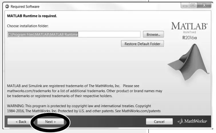
The software was developed with Matlab 2015b and requires Matlab programming libraries. At the very first installation user should refer to the installation package, available from the RCF website, containing the Matlab Runtime (ver. 9) or the installation package that will download the Runtime from the web. Once the libraries are correctly installed, for all the following version of the software the user can directly download the application without the Runtime. Two versions, 32-bit and 64-bit, are available for the download. IMPORTANT: Matlab no longer supports Windows XP and hence RCF Easy Shape Designer (32 bit) doesn’t work with this OS version.
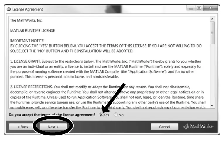
You may wait a few seconds after the double click on the installer because the software checks if Matlab Libraries are available. After this step the installation begins. Double-click the last installer (check for the last release in the download section of our website) and follow the next steps.
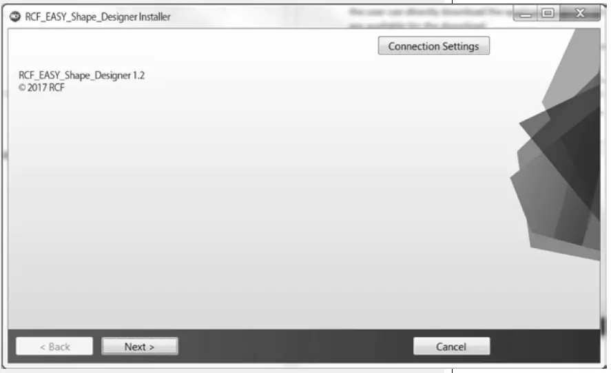
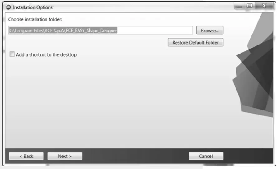
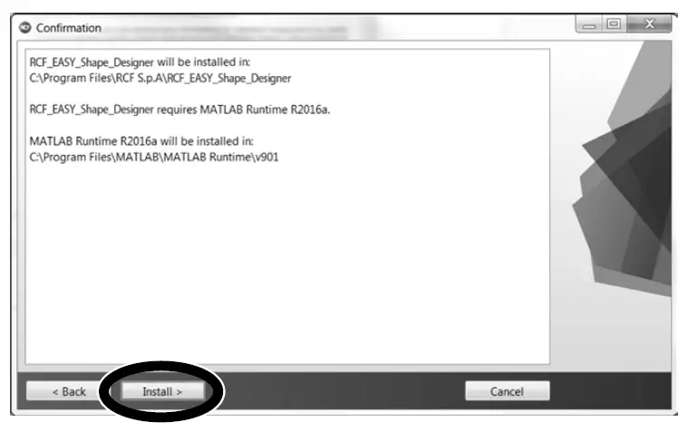
After the choice of folders for RCF Easy Shape Designer software (Figure 2) and Matlab Libraries Runtime the installer takes a couple of minutes for the installation procedure. 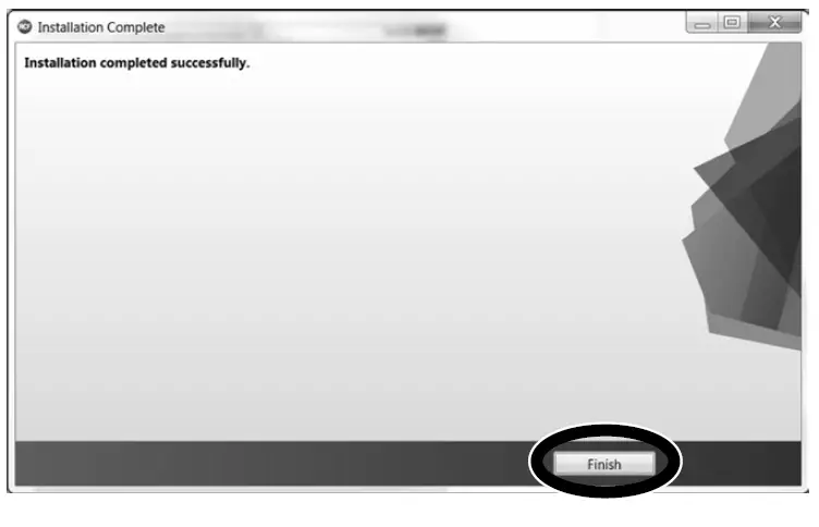
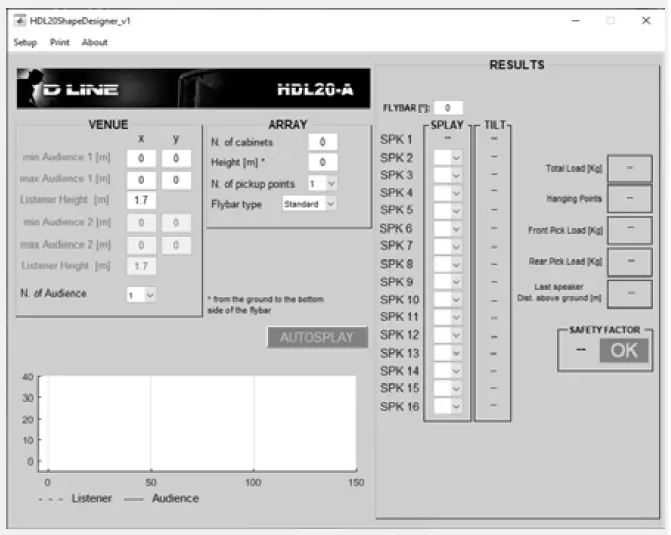
The RCF Easy Shape Designer software is divided into two macro sections: the left part of the interface is dedicated to project variables and data (size of audiences to cover, height, number of modules, etc.), the right part shows the processing results. At first the user should introduce the audience data choosing the proper pop-up menu depending on the size of the audience and introducing the geometrical data. It is also possible to define the height of the listener.
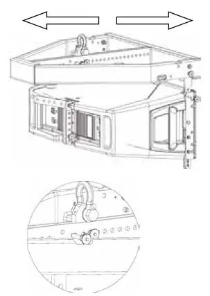
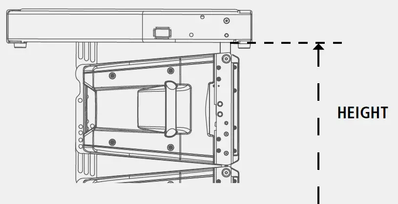
The second step is the array definition selecting the number of cabinets in the array, the hanging height, the number of hanging points and the kind of available flybars. When selecting two hanging points consider those points positioned at the flybar extremes. The height of the array should be considered referred to the bottom side of the flybar, as shown in the picture below.
After entering all the data input in the left part of the user interface, by pressing the AUTOSPLAY button the software will perform:
- Hanging point for the shackle with A or B position indicated if a single pickup point is selected, rear and front load if two pickup points are selected.
- Flybar tilt angle and cabinet splays (angles that we have to set to each cabinet before lifting operations).
- Inclination that each cabinet will take (in case of one pick up point) or will have to take if we were to tilt the cluster with the use of two engines. (two pick up points).
- Total load and Safety Factor calculation: if the selected setup doesn’t give Safety Factor > 1.5 the text message shows in red color the failure to meet the minimum conditions of mechanical safety.
- Low Frequency Presets (a single preset for all the array) for RDNet use or for rear panel rotary knob use (“Local”).
- High Frequency Presets (a preset for every array module) for RDNet use or for rear panel rotary knob use (“Local”).
OPTIMIZING THE ARRAY
- Once the design (number of elements and vertical splay angles) has been designed using Shape Designer software, you can effectively optimise the array depending on the environment and the application by driving it using different DSP presets stored onboard. Typically arrays are divided in two or three zones depending the design and size of the array.
- To optimise and EQ the array, different strategies are used for high frequencies (long throws and short throws) and low frequencies.
- The longer the distance, the greater the attenuation at high frequencies. Generally, high frequencies need a correction to compensate for energy lost over distance; the correction needed is usually proportional to the distance and high-frequency air absorption. In the near- to mid-field, the air absorption is not nearly as critical; in this zone, high frequencies need little additional correction.
In the next figure is shown the equalization that corresponds to HF settings for NEAR and FAR: 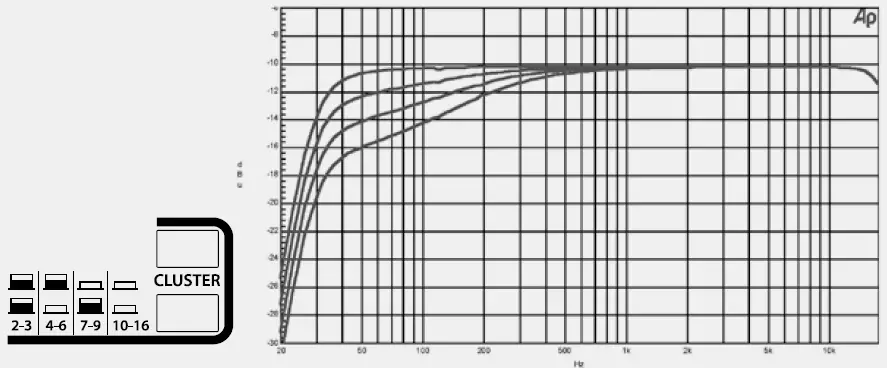
- While wave-guides provide isolated control over various mid- to high-frequency coverage areas, the low-frequency section of a HDL array still requires mutual coupling – with equal amplitude and phase – to achieve better directionality. Low-frequency directionality is less dependent on the array’s relative splay angles and more dependent on the number of elements of the array.
- At low frequencies, the more elements in the array (the longer the array), the more directional the array becomes, providing more SPL in this range. The directional control of the array is achieved when the length of the array is similar or larger than the wavelength of the frequencies being reproduced by the array.
- Although the array can (and usually should) be zoned for implementing different equalization curves for high frequencies, identical equalization should be maintained in all the low-frequency filters.
- Different low-frequency equalization settings in the same array will degrade the desired coupling effect. For the same reason, gain differences are not recommended for line arrays, since adjusting various zones with an overall amplitude control for each results in decrease of Low-frequency headroom and directionality.
- In any case, line arrays generally need a correction to compensate for energy sum on lows.
- In the next figure is shown the equalization that corresponds to CLUSTER settings, referring to different number of speakers from 2-3 up to 10-16. Increasing the number of cabinets, response curves are decreased in order to compensate the low-frequency section mutual coupling.
HIGH-FREQUENCY EQUALIZATION STRATEGIES
LOW-FREQUENCY COUPLING EFFECTS
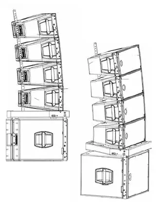
HDL10-A & HDL20-A GROUND STACKED
HDL modules can still be stacked on top of RCF subwoofers using the HDL fly bar.
HDL 20-A compatible Subwoofers:
- SUB 8004-AS
- SUB 8006-AS
- HDL 18-AS
HDL 10-A compatible Subwoofers:
- SUB 8004-AS
- SUB 8006-AS
- HDL 15-AS
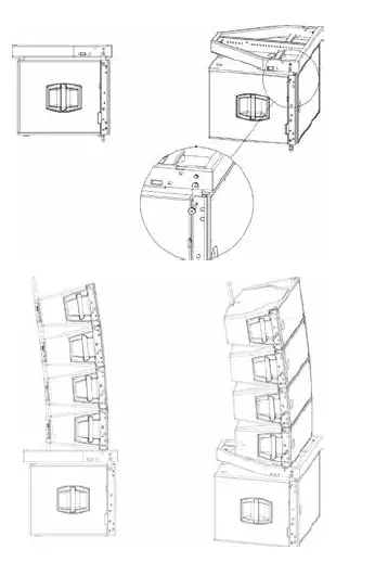
- Fix the HDL fly bar on subs as shown in the picture.
- The stacking bar adds a fixed amount of up or downtilt to ground-stacked HDL modules, with additional 15 degrees of adjustment possible (from +7,5° to -7,5°).
- Connect front bracket of the first HDL cabinet using 2 quick lock pins.
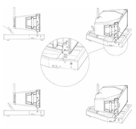
- The baffle of the bottom box in a stacked array does not necessarily have to be parallel to the stage or the array frame. It can be tilted up or downward if desired. In this way arced arrays can be readily created from a ground stack position.
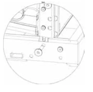
- The bottom box in a stacked array can be tilted to obtain proper coverage patterns (from+7,5° to -7,5°). Reverse and connect the 1 rear stacking bar bracket to the first enclosure using the hole for the proper angle and quick lock pins.
Add HDL cabinets one by one as indicated for flown configurations. Up to four HDL enclosures can be stacked and interlinked using the standard D LINE rigging components and the D LINE subs as ground support.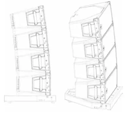
- It is possible to stack HDL speakers on the ground using its own fly bar as shown in the pictures.
RCF S.p.A.
Via Raffaello Sanzio, 13 42124 Reggio Emilia – Italy T
- el +39 0522 274 411
- Fax +39 0522 232 428
- e-mail: info@rcf.it
Frequently Asked Questions
- Q: Can I use this product outdoors?
A: To prevent the risk of fire or electric shock, it is advised not to expose this product to rain or humidity. - Q: What should I do if I detect strange odors coming from the product?
A: Immediately switch off the product, disconnect the power cable, and contact authorized service personnel for assistance.
Documents / Resources
 |
RCF HDL20-A Active 2 Way Dual 10 Line Array Module [pdf] Instruction Manual HDL20-A Active 2 Way Dual 10 Line Array Module, HDL20-A, Active 2 Way Dual 10 Line Array Module, 10 Line Array Module, Array Module |