![]() Networked Media Processor
Networked Media Processor
NMP221-R-CU/NMP221-R-LU
Quick Guide
Product introduction
The Q-NEX Networked Media Processor integrates the Ethernet connection into the device control system, allowing users to remotely control the device. It is mainly designed for assisting school’s IT admin to well manage various electronic facilities in a school, and freeing teachers from complicated operation of a multimedia classroom.
Components of NMP

2.1 NMP front view

- Wireless microphone channel
- RF: wireless microphone radio frequency indicator
- DOWN: switch channel down
- UP: switch channel up
- AF: wireless microphone audio frequency indicator
- POWER-VOL: wireless microphone volume knob
2.2 NMP rear view interfaces
| ① RJ45 ② 3* 3HDMI matrix ③ Display power supply ④ Electronic projection screen power supply ⑤ NMP power supply ⑥ External device Single pole double throw power relay ⑦ Power fuse ⑧ Electric lock control ⑨ External speaker output |
⑩ Audio output ⑪ Audio input ⑫ Mic output ⑬ Mic input ⑭ Smart touch USB ports (1&2 for USB Host, 3 for USB Device) ⑮ USB2.0 ports ⑯ IR learner port ⑰ Control Panel connection ⑱ RS232 |
2.3 Control panel features

- Computer: indicator on means HDMI out A switched to HDMI in 1, recommend PC as input.
- Visualizer: indicator on means HDMI out A switched to HDMI in 2, recommend visualizer as input
- HDMI 3: indicator on means HDMI out A switched to HDMI in 3
- Display: indicator on means power on the device connected to Display
- Light: indicator on means power on the device connected to External, recommend light
- Main power: indicator in blue/red means power on/off
- MIC: to control volume of mic when the indicator is on, to control volume of speaker when the indicator is off
- VOL.-: the indicator is on when volume is down to the least
- VOL indicator light: more indicators on as volume increases
- IC Card Area: tap the IC card to unlock the panel, can power on NMP when it’s off
- VOL.+:the indicator is on when volume is up to the max.
- Mute: indicator on means the speaker is mute
- Lock: indicator on means the panel is locked
2.4 Touch panel features
2.5 Handheld mic features

- LCD screen
- Power
a. Press once to power on, long press to power off.
b. When the handheld microphone is on, press the power button to switch to the next channel.
c. When the handheld microphone is on, continuously click the power button three times to enter the pairing mode.
2.6 Lapel mic features

- Lapel mic port
- Power button
- Antenna
- LCD screen
- Volume adjust
- Channel pairing: press three times to enter the pairing mode, the LCD screen displays IR—; press to switch channels
2.7 Pairing Touch Panel with Wireless Mic Pairing steps:
- Power on microphone and enter pairing mode.
For Handheld microphone: Press power button 3 times to enter pairing mode
 For Lapel microphone – press round button 3 times to enter pairing mode

- Then click on touch Panel or swipe a IC card to turn on NMP, the microphones will automatically pair with the receiver built in the NMP.
 When it is successfully paired, the indicator in front of NMP will turn green as below:

Note:
- Don’t turn on Q-NEX NMP before setting the wireless microphones in pairing mode, otherwise, the pairing process will fail!
- Both handheld and lapel microphones are paired with NMP accordingly already before leaving factory, so you DON’T have to pair them when it is FIRST TIME to unbox Q-NEX NMP.
Get ready before installation
3.1 Require an Admin account of Q-NEX Console from Q-NEX team.
Log in https://mg.qnextech.com/. and bind in NMP devices to a created virtual organization in the system for identification.
3.2 Prepare the power cable for power out of Display:
- Uncovered copper wire length>=10mm
- Wire cable with insulation paste>=25mm
- Tighten the single copper wire

3.2.1 Pry open the shrapnel inside the hole with a screwdriver, in the meantime, insert the thread. Release the screwdriver, the thread will be fastened inside the WAGO. At last, pull the wire to check if it is fixed tightly.
3.2.2 After placing the wires, use the Wire Protection Clip to fasten.
Then put on the Shell Base and Shell Cover.
3.3 Prepare the power cable for SPDT switch of External:
3.4 RS232 connection for projector:
For the other end, wiring according to the wiring instructions of the controlled equipment. 3.5 Speaker connection
3.6 Electric lock connection
Please connect the required interface according to your electronic lock type.
 +: Power output 12V800mA
-: Power ground (negative level)
I: Door switch interface
D: Door lock status interface
C: Relay common end, load capacity DC3A/30V
O: Relay normally open, load capacity DC3A/30V
Wiring and setup
Please follow the instructions below to connect the cables
Note: Installation and repair should only be performed by authorized personnel.
4.1 Basic installation
Connect the NMP power cable to “POWER IN”.
For Control Panel
Connect the control panel to the NMP “PANEL” port:
If the power indicator on control panel is red, that shows the connection is well done. Now touch the main power button, the power indicator light turns in blue, which means it is booted successfully.

For Touch Panel
(Connect to NMP with CAT Cable)
- Screw the wall mount bracket to the desktop stand.
- Connect the Touch Panel to network and power up. There are three ways for connection:
• Connect Touch Panel to NMP by network cable, and power through 12V adapter.
• Connect Touch Panel and NMP to the same switch, and power Touch Panel through 12V adapter.
• Connect both Touch Panel and NMP to one PoE switch, then no powersupply is required for Touch Panel.
Note:
• The LAN ports NMP 221-R don’t support POE.
• Touch Panel must be on the same LAN as NMP.
Warning
Do not power Touch Panel through adapter and POE at the same time, it will cause Touch Panel to be short-circuited and burned.
This kind of damage is not covered by the warranty. - Fasten the wall-mounted bracket into the slots of Touch Panel and make sure it is fixed.
- Initial settings
Make sure that NMP is connected to the network (refer to NMP Quick Guide). Log in to the Q-NEX Dashboard -Devices-Processor Manager and check the IP address of this NMP.

Input the IP address on the Touch Panel and click Connect. It will enter the homepage of Touch Panel after connecting successfully.

Connect NMP to the Ethernet :
 If the yellow and green LED light of Ethernet port is flickering, which means the network connection is successful.
Add NMP to Console By web:
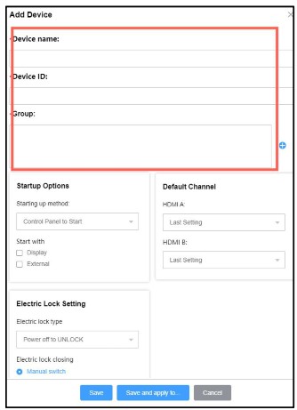
Log in to Q-NEX dashboard (check your email for the initial administrator account / password), enter the Device/Processor Manager page, and click on the “Add Device” to add a new NMP into the system:
Put in a device name (can be “Classroom One”, for example) and device ID indicated on NMP (product S/N). Select a group where the NMP is classified (for example, “Grade One” in a school). Set the startup linkage parameters as required, and click Save:
When the NMP device info is successfully submitted, and verified by Q-NEX system online, the “Status” will turn green.

Add NMP to Console By APP:
Scan the QR code on the NMP through the scan button on the device page and follow the steps to add the new NMP.

4.2 Power control DISPLAY:
Replace the plug of the display devices (projector and projection screen, TV, IFP, etc.) with WAGO connector, Connect the WAGO connector to the DISPLAY port of NMP.
To realize power control of devices with RS232 connection (e.g., projector),please connect the device through the RS232 of NMP as well.
EXTERNAL:
For other devices that need to control power, such as lights, please connect the device to the EXTERNAL power switch control port according to the installation of a single-pole double-throw switch:

Warning: Do not input power to “External”, otherwise it will cause NMP irreparable fatal failure.
Note:
- Keep the gross output power of both “Display” and “Screen” port under 1,200 W.
- The current-carrying capacity of the “External” switch should not exceed 1200W
Power control of control panel or touch panel:

SCREEN:
Replace the plug of projection screen with WAGO connector, connect to SCREEN port. (Note: Projection screen only)
Projection screen up and down can be controlled via Q-NEX Console, mobile APP or Touch Panel after successful connection. 
4.3 Video matrix switch
NMP supports HDMI output to three displays. Connect display devices, like TV, projector, and IFP, to HDMI OUT, and connect HDMI devices, such as PC, document camera, IQ Share etc., to HDMI IN.
Both control panel and touch panel only control the input source switching of HDMI out A, press the button to switch directly to the corresponding channel, and the signal light is on.

Please operate on Q-NEX APP or Q-NEX Console to switch the input source of HDMI out B and HDMI out C.
Touch USB: Route touch signals from different HDMI inputs to a touch display (should be HDMI A).
For example, if an interactive flat panel (as HDMI A) can work with a PC for 10 touches, but only one touch with a document camera, then when switching signal from PC to document camera, the interactive flat panel will accordingly enable 10 touches to one touch.
Note: The Touch USB feature works only when the touch display is compatible with the input devices for touch.

4.4 Audio control
NMP has a built-in power amplifier, 2*(40w+40w), that can be connected to passive speakers. Replace the speaker cable with a Phoenix audio connector and plug into the speaker interface. Up to two pairs of passive speakers can be connected.
Volume adjustment or mute can be operated via control panel or touch panel. Sound muted when MUTE lights up.

Touch panel can also adjust treble and bass, switch the audio source of HDMI out A as well.

Through 3.5mm line in, NMP can support devices with audio output such as mobile phones, operation can be done via control panel-AUDIO.

4.5 Microphone control
4.5.1 Wireless microphone connection:
Put the wireless microphone close to the NMP and turn it on.
After frequency pairing is successful, there will be a beep and the corresponding MIC indicator on the front of the NMP will light up.
4.5.2 Wired microphone connection:
The wired microphone can be connected to the NMP through a 6.5mm mic cable. Sound of wired and warless microphone get mixed and output.
 4.5.3 Microphone volume adjustment:
For Control Panel
The microphone is under control when it lights up. At this time, the operations of increasing the volume, decreasing the volume and muting are only for the microphone.
For Touch Panel
Touch panel can adjust microphone volume, treble and bass.

4.6 Air-conditioner control
Connect infrared transmitter to “IR” port of NMP, and aim the transmitter at the air conditioner, and ensure there should be no blocks in between the transmitter and the air conditioner.
 Login Q-NEX console -> Dashboard -> Devices -> Processor manager.
Select infrared control edit module of a certain NMP to identify the new A/C control code, follow the instruction as below:
- Click the “New A/C control code” then the “start ” button
- While analyzing, aim the A/C remote control at the infrared learning hole on NMP, and press the power button
- After identified successfully, fill in the A/C brands, models, and save
- Select the air-conditioner control code from pull-up menu, and save.
- Now control the air conditioner on Q-NEX Console or touch panel.

 4.7 IR remote control settings
IR remote control module is available for unrecognized air conditioners or other devices using infrared remote control.
Connect infrared transmitter to “IR” port of NMP, and aim the transmitter at the device, and ensure there will be no blocks in between the transmitter and the device.
Login Q-NEX console -> Dashboard -> Devices -> Processor manager.
Select infrared control edit module of a certain NMP to learn the new remote control code, follow the instruction as below:
- click the “New remote control code”
- Choose the type of IR control device
- Click “start to learn”
- While analyzing, aim the remote control at the infrared learning hole on NMP, and then press the function button
- After identified success, add information of control code and save.
- Select the target remote control code, save and done.
- Remote control on Q-NEX Console or touch panel.


Common problems and solutions
Problem:
The microphone button will flash when you long press it. It means entering the pairing state of the WX-U32 microphone.
Solution:
It is non-fault problem. No need to operate, just wait a few seconds and use it as normal.
If you encounter any problems during installation and use, please contact us: info@qnextech.com
As of the date of manufacture, the product has been tested and found to comply with specifications for CE marking.

Returnstar Interactive Technology Group Co., Ltd.
![]() www.QnexTech.com
www.QnexTech.com
![]() info@QnexTech.com
info@QnexTech.com
![]() 6th Bldg. High-Tech Base. Fuzhou Fujian Prov. China
6th Bldg. High-Tech Base. Fuzhou Fujian Prov. China![]()
Documents / Resources
 |
Q-nex NMP221-R-CU Networked Media Processor [pdf] User Guide NMP221-R-CU Networked Media Processor, NMP221-R-CU, Networked Media Processor, Media Processor, Processor |
 |
Q-nex NMP221-R-CU Networked Media Processor [pdf] User Guide NMP221-R-CU, NMP221-R-LU, NMP221-R-CU Networked Media Processor, Networked Media Processor, Media Processor, Processor |


