![]()
USER MANUAL
Q210 PW – Speaker
Station
Q-Series Network Based Intercom System
Q210PW Network Based Intercom System

This manual is applicable for Firmware Version: 2.1
© 2024 Riedel Communications GmbH & Co. KG. All rights reserved. Under the copyright laws, this manual may not be copied, in whole or in part, without the written consent of Riedel. Every effort has been made to ensure that the information in this manual is accurate.
Riedel is not responsible for printing or clerical errors. All trademarks are the property of their respective owners.
Preface
Welcome to the punQtum digital intercom family!
This document provides detailed information about the punQtum Q-Series digital partyline system, pin outs, mechanical and electrical data.
NOTICE
This manual, as well as the software and any examples contained herein are provided “as is” and are subject to change without notice. The content of this manual is for informational purposes only and should not be construed as a commitment by Riedel Communications GmbH & Co. KG. or its suppliers. Riedel Communications GmbH & Co. KG. gives no warranty of any kind with regard to this manual or the software, including, but not limited to, the implied warranties of marketability or fitness for a particular purpose. Riedel Communications GmbH & Co. KG. shall not be liable for any errors, inaccuracies or for incidental or consequential damages in connection with the furnishing, performance or use of this manual, the software or the examples herein. Riedel Communications GmbH & Co. KG.
reserves all patent, proprietary design, title and intellectual property rights contained herein, including, but not limited to, any images, text, photographs incorporated in the manual or software.
All title and intellectual property rights in and to the content that is accessed through use of the products is the property of the respective owner and is protected by applicable copyright or other intellectual property laws and treaties.
1.1 Information
Symbols
The following tables are used to indicate hazards and provide cautionary information in relation to the handling and use of the equipment.
![]() This text indicates a situation that needs your close attention. It may also be used to alert against unsafe practice.
This text indicates a situation that needs your close attention. It may also be used to alert against unsafe practice.
![]() This text is for general information. It indicates the activity for ease of work or for better understanding.
This text is for general information. It indicates the activity for ease of work or for better understanding.
Service
- All service must be provided ONLY by qualified service personnel.
- There are no user-serviceable parts inside the devices.
- Do not plug in, turn on or attempt to operate an obviously damaged device.
- Never attempt to modify the equipment components for any reason.
All adjustments have been done at the factory before the shipment of the devices. No maintenance is required and no user-serviceable parts are inside the unit.
![]() Environment
Environment
- Never expose the device to high concentrations of dust or humidity.
- Never expose the device to any liquids.
- If the device has been exposed to a cold environment and transferred to a warm environment, condensation may form inside the housing. Wait at least 2 hours before applying any power to the device.
Disposal
![]() This symbol, found on your product or on its packaging, indicates that this product should not be treated as household waste when you wish to dispose of it.
This symbol, found on your product or on its packaging, indicates that this product should not be treated as household waste when you wish to dispose of it.
Instead, it should be handed over to an authorized collection point for the recycling of electrical and electronic equipment. By ensuring this product is disposed of correctly, you will help prevent potential negative consequences to the environment and human health, which could otherwise be caused by inappropriate disposal of this product. The recycling of materials will help to conserve natural resources. For more detailed information about the recycling of this product please contact the local authority responsible.
2 About punQtum Q-Series Digital Partyline Intercom System
punQtum Q-Series digital partyline intercom system is a digital, easy to use, full-duplex communications solution for theater and broadcast applications as well as for all kinds of cultural events like concerts, etc.
It is an all-new, network-based partyline intercom system which combines all standard partyline system features including wireless access and more with the advantages of modern IP networks. punQtum Q-Series works on standard network infrastructure and is easy to install and set up. The system works “out of the box” with a factory default configuration but can be quickly configured by user-friendly software to meet individual needs. The system is completely decentralized. There is no master station or any other central point of intelligence in the whole system. All processing is handled locally in each device except for the punQtum wireless Apps which require a punQtum Q210 PW Speaker Station to serve as a bridge to the Q-Series digital partyline intercom system. The capacity of one partyline intercom system is set to a maximum of 32 channels, 4 program inputs, up to 4 public announce outputs and 32 control outputs. Each punQtum Q210 PW Speaker Station serves up to 4 punQtum Wireless App connections.
punQtum Q-Series digital partyline systems are based on Roles and I/O settings to ease the use and administration of partyline intercom systems.
A Role is a template for the channel configuration of a device. This allows channel settings and alternate functions to be predefined for different Roles needed to run a live show. As an example, think of the stage manager, sound, light, wardrobe and security personnel having different communication channels available to deliver a perfect job.
An I/O setting is a template for the settings of the equipment connected to a device. This, for example, allows I/O settings to be available for different Headsets being used at a venue to cover for different environmental situations.
Each device can be configured to any Role and I/O setting available.
Multiple punQtum partyline intercom systems can share the same network infrastructure. This allows for the creation of production islands within a campus using the same IT network infrastructure. The number of devices (Beltpacks/Speaker Stations and Wireless Apps) is 0theoretically infinite but limited by the network capacity. Beltpacks are powered by PoE, either from a PoE switch or from a Speaker Station. They can be daisy-chained to reduce wiring efforts on site.
Beltpacks and Wireless Apps support simultaneous use of 2 channels with separate TALK and CALL buttons as well as one rotary encoder for each channel. An alternate page button allows the user to quickly reach alternate functions such as public announce, Talk To All, Talk To Many, to control general purpose outputs and access system functions like Mic Kill asf. The Beltpack is designed with a combination of premium materials, including highimpact plastics and rubber to make it both tough and comfortable to use in any situation.
punQtum Q-Series Beltpacks, Wireless Apps and Speaker Stations allow users to replay missed or not understood messages. Program input signals can be fed into the system using an analog audio input at any Speaker Station. Sunlight readable, dimmable RGB color displays used for Beltpacks and Speaker Stations make for excellent readability of the intuitive user interface.
Front Panel Operating Elements 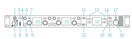
- Gooseneck mic connector
- Headset connector
- Headset/Gooseneck selector
- Headset/Gooseneck LED
- USB host connector
- Rotary encoder
- REPLAY button
- CALL button
- TALK button
per channel - Color TFT display
- Mic Mute button
- Mic KILL button
- A/B/C/D buttons
- VOLUME button
- Alternate page button
- BACK button
- Main Rotary encoder
- Speaker-Muted LED
Back Panel Connectors 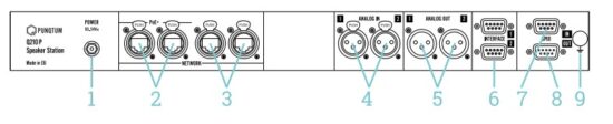
- DC power connector
- Network with PoE+ output
- Standard Network
- Balanced analog inputs
- Balanced analog outputs
- Interface ports
- GPI inputs
- GPI outputs
- Protective earth screw
punQtum Wireless App support
The Q210 PW Speaker Station serves up to four connected punQtum Wireless Apps.
Factory default configuration allows a maximum of four active connections without user/ password authentication.
The configuration of wireless access functions is done using Q-Tool. Each Q210 PW Speaker Station enables transparent use of such configuration without any local user interface on the Q210 PW Speaker Station.
Use your Q210PW Speaker Station at any position in your setup and profit from the wireless functionality at the same time!
Getting Started
The Q210 P Speaker Station is your intercom network center. It is delivered with a factory default system configuration and will work “out of the box” together with Q110 Beltpacks in factory default system configuration.
The Speaker Station supports the use of a monaural headset or a gooseneck microphone used together with the built in or an externally connected speaker. The Speaker Station supports the use of both dynamic and electret microphones.
6.1 Powering Up
Only use the provided AC/DC power adapter for powering the Q210 PW Speaker Station. Always leave the DC plug connected to the Speaker Station and switch power on the AC side only.
Do not connect outputs of PoE capable switches to the PoE+ ports of the Speaker Station as they might show non PoE standard behavior and provide power to the Speaker Station as well.
6.2 Back Panel Connections
The Q210 P Speaker Station provides 4 network switch connectors, 2 analog inputs, 2 analog outputs, 4 general purpose inputs, 4 general purpose outputs and 2 universal interface onnections to complete your system. The factory default system configuration supports plug and play use of the network switch connectors and all analog inputs and outputs. 
6.2.1 Network Switch Connections
The Q210 P Speaker Station provides 4 network switch ports to connect Q110 Beltpacks and other equipment.
The network ports labeled PoE+ provide power to 4 daisy chained Q110 Beltpacks each. No additional network equipment is needed to run punQtum Q-Series digital partyline intercom systems. However, punQtum Q-Series digital partyline intercom systems can easily be integrated into existing network infrastructure using the non PoE+ ports.
6.2.1.1 Multicast Audio Streams
If you do not have any other audio streams present in your network infrastructure, you will most probably be fine.
If you are using punQtum Q-Series digital partyline intercom systems in networks together with other audio network streaming technologies such as Ravenna, DANTE or other multicast-based streaming technologies, you need to make sure that your network infrastructure is capable of supporting IGMP (Internet Group Management Protocol) and that IGMP is correctly set up and configured:
Avoid connecting outputs of PoE capable switches to the PoE+ ports of the Speaker Station as they are also capable of providing PoE power.
If you use a single switch only, it is irrelevant if the switch has IGMP snooping (aka multicast filtering) enabled or not. As soon as you have two switches, and one or more switches happen to have IGMP snooping enabled, it is necessary to configure one and only one IGMP querier in the network (usually, you select one switch). Without an IGMP querier, the multicast traffic will stop after a while due to IGMP timeouts. punQtum Q-Series digital partyline system supports IGMP V2.
6.2.2 Connecting Program Signals and Public Address Outputs
2 independent program signals can be connected to the balanced analog inputs. On each device of your system, you can select which program input shall be heard.
Analog Input Connector: Type XLR 3pin, female![]()
| Pin | Name | Description |
| 1 | GND | Audio ground and shield |
| 2 | A+ | Audio (positive) |
| 3 | A- | Audio (negative) |
Please refer to the datasheet for technical details.
2 independent public address signals are available as balanced analogue outputs. Connect your lobby speakers and your wardrobe speakers to these outputs for example.
Analog Output Connector: Type XLR 3pin, male![]()
| Pin | Name | Description |
| 1 | GND | Audio ground and shield |
| 2 | A+ | Audio (positive) |
| 3 | A- | Audio (negative) |
Please refer to the datasheet for technical details.
6.2.3 Interface ports
The Q210 P Speaker Station provides 2 interface ports to be used with cameras and other external equipment. Interface ports carry Channel and Program audio signals and are freely configurable in Q-Tool. Please consult Q-Tool help for more details. Interface ports are not part of the factory default configuration system.  Each interface provides the option to enable split mode:
Split mode adds the interface input signal received to the interface output directly.This is helpful to connect VHF radio systems for example.
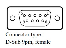
| Pin | Name | Description | ||
| 1 | Audio Out + | Balanced audio output (positive) | ||
| 2 | GP Out A | General-purpose output (positive) | ||
| 3 | GND | Audio ground | ||
| 4 | GP In B | General-purpose input (negative) | ||
| 5 | Audio In – | Balanced audio input (negative) | ||
| 6 | Audio Out – | Balanced audio output (negative) | ||
| 7 | GP Out B | General-purpose output (negative) | ||
| 8 | GP In A | General-purpose input (positive) | ||
| 9 | Audio In + | Balanced audio input (positive) | ||
The electrical specification for the GP Inputs and Outputs present on the universal connectors are the same as for the General Purpose Interfaces. Please refer to the datasheet for details.
6.2.4 General Purpose Inputs
General purpose inputs (GPI) can be used to control system functions or act the same as buttons available on the Q210 P Speaker Station front panel. They can also be assigned to any of control channels available per punQtum Q-Series digital partyline system.
GPI are freely configurable in Q-Tool. They are not used as part of the factory default configuration system.
GPI are galvanically isolated current sensing inputs. Please refer to the datasheet for details.
| Pin | Name | Description |
| 1 | GP In-1 + | General-purpose input #1 (positive) |
| 2 | GP In-2 + | General-purpose input #2 (positive) |
| 3 | GP In-3 + | General-purpose input #3 (positive) |
| 4 | GP In-4 + | General-purpose input #4 (positive) |
| 5 | GND | Power ground |
| 6 | GP In-1 – | General-purpose input #1 (negative) |
| 7 | GP In-2 – | General-purpose input #2 (negative) |
| 8 | GP In-3 – | General-purpose input #3 (negative) |
| 9 | GP In-4 – | General-purpose input #4 (negative) |
6.2.5 General Purpose Outputs
General purpose outputs (GPO) can be used to make system, call or talk states of partylines available externally. They can also represent the state of one of the 32 freely assignable control channels available per punQtum Q-Series digital partyline system.
GPO are freely configurable in Q-Tool. They are not used as part of the factory default configuration system.
GPI are galvanically isolated switching outputs. Please refer to the datasheet for technical details.
| Pin | Name | Description |
| 1 | GP Out-4 A | General-purpose output #4 (A) |
| 2 | GP Out-3 A | General-purpose output #3 (A) |
| 3 | GP Out-2 A | General-purpose output #2 (A) |
| 4 | GP Out-1 A | General-purpose output #1 (A) |
| 5 | +5V | 5V power (max. 150mA) |
| 6 | GP Out-4 B | General-purpose output #4 (B) |
| 7 | GP Out-3 B | General-purpose output #3 (B) |
| 8 | GP Out-2 B | General-purpose output #2 (B) |
| 9 | GP Out-1 B | General-purpose output #1 (B) |
6.3 Front Panel Connections
6.3.1 Gooseneck Microphone Connector

| Pin | Description |
| Tip | Microphone + / +5V bias voltage for electret mic |
| Ring | Microphone – |
| Sleeve | Microphone – / GND |
The gooseneck microphone connector is a 1/4“/6.3 mm Jack TRS connector with 7/16“ -20 UNF thread. It supports electret or dynamic microphones.
The microphone bias power (+5.8V) will be switched on/off according to the mic type setting. This can be changed directly in the Speaker Station menu 8.6.2
6.3.2 Headset Connector
| Pin | Description |
| 1 | Microphone – |
| 2 | Microphone + / +5V bias voltage for electret mic |
| 3 | Earphones – |
| 4 | Earphones + |
The headset connector is a 4-pole male XLR connector and supports monoaural headsets with electret or dynamic microphones.
The microphone bias power (+5.8V) will be switched on/off according to the mic type setting. This can be changed directly in the Speaker Station menu 8.6.2
Using your Speaker Station
A Speaker Station that is “new out of the box” includes a factory default system configuration. This allows all devices in factory default configuration to communicate without the need of the Q-tool configuration software.
7.1 Front Panel operation elements ![]()
7.1.1 Headset Mic/Gooseneck Mic selector
Change between using a connected headset or a connected gooseneck microphone plus the built-in speaker for communication. The selected mode is indicated using LED’s. If Headset is selected, a speaker mute indicator ![]() is lit in addition.
is lit in addition.
Using Q-tool, you have the option to direct the speaker signal to one of the analog outputs instead of to the speaker.
Volumes of headset and speaker output can be set individually.
7.1.2 Channel rotary encoder ![]()
Moving the rotary knob clockwise will increase the volume, counterclockwise operation will decrease the volume.
Pushing the rotary encoder will mute / unmute the Channel.
7.1.3 Channel replay button ![]()
Use this button to start the replay of the last recorded message of a channel. See Replay available indication (K) for additional information on the replay function.
7.1.4 Channel CALL button ![]()
Use this button to issue a CALL signal on the Channel. If the CALL signal remains active for more than two seconds by pushing a call button for more than 2 seconds an ALARM signal will be issued on the channel. See 7.2.4 for additional information on the CALL function.
7.1.5 Channel TALK button ![]()
Use this button to talk to the Channel. A talk button offers different operation modes explained here: 7.2.5
7.1.6 Mic Mute button ![]()
Use this button to quickly mute the microphones connected to your Speaker Station. This is a handy feature to avoid any unwanted communication to any otherwise active channel when you have to discuss something with a person coming to your desk.
Active mic mute is shown on your Speaker Station like this: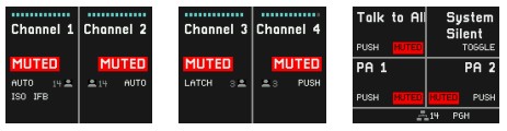
7.1.7 Mic KILL button![]()
Clicking the Mic Kill button on a device will reset all active TALK functions of the channels the device Role is assigned to except for the TALK functions active on the device where Mic Kill is issued. A long press on the Mic Kill button will reset all active TALK functions of all channels available in the system configuration except for the TALK functions active on the device where Mic Kill is issued. The purpose of this function is to be able to ‘silence’ overly busy channels to be able to transmit important / urgent messages.
The Mic Kill button can be disabled in the role settings to avoid unwanted interference. Please note that the mic kill function is not applied to interface connections, because they are typically used to interconnect different communication systems. Mic kill functions can be propagated to and received from other systems using the GPIO ports on a punQtum Speaker Station.
7.1.8 A/B/C/D Buttons![]()
Pressing the A/B/C/D buttons gives you direct access to functions like Public Announce, Talk To All and Talk To Many, Control switching, System Mute, System Silent and Mic Kill. You can assign any of above functions to a Button of your choice using Q-tool configuration software.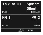 7.1.9 Volume Button
 ![]()
Pressing the Volume Button will cycle you through all available volume settings depending on your headset/speaker selection: 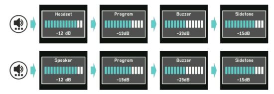
You may adjust each volume setting using the main rotary encoder. Your settings are stored in your Speaker Station.
Headset volume sets the overall volume for your headset.
Speaker volume sets the overall volume for your built-in or external speaker connected.
Program volume controls the volume of your program input.
Buzzer volume controls the volume of the CALL and ALARM signals.
Sidetone volume controls the volume of your own voice.
7.1.10 Alternate Page button ![]()
Pressing the Alternate Page button will temporarily give access to an additional set of four functions like public announce, Talk To All and Talk To Many, controls switching, System Mute, System Silent and Mic Kill. You can assign a maximum of 4 functions to button A/B/C/D of the alternate page using Q-tool configuration software.
A yellow bottom bar indicates an active alternate page. A second press on the Alternate Page button or a press on the Back button will leave the alternate page.
If no functions are assigned to the alternate page, the Alternate Page button is inactive.
7.1.11 Main Rotary Encoder ![]()
Use the main rotary encoder to adjust the output volume of your Speaker Station.
Pushing the main rotary encoder gives access to the setup menu. See Chapter Menu operation.
A long press on the main rotary encoder briefly shows the device model, device name and installed FW version. 7.1.12 Back Button
 ![]()
Use the Back button to navigate backwards in the menu or to leave the alternate page.
7.2 Channel Displays
The left and middle Speaker Station displays show information on status and configuration of the channels activated for the current role.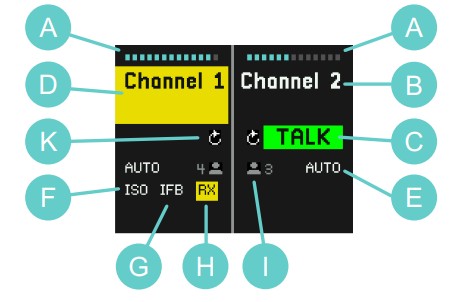 A Channel volume
B Channel name
C TALK active indication
D CALL active indication
E TALK button operation mode
F ISO active indication
G IFB active indication
H Audio receive indication
I Channel user count
K Replay available indication
7.2.1 Channel Volume (A)
Channel volume control can be set by the rotary encoder knobs (6 on Front Panel Operating Elements) next to the replay button of each channel of the Speaker Station. Moving the rotary knob clockwise will increase the volume, counterclockwise operation will decrease the volume. Pushing the rotary encoder will mute / unmute the Channel.![]() 7.2.2 Channel Name (B)
7.2.2 Channel Name (B)
The Channel Name shown is the Name as defined in the system configuration using Q-Tool. 7.2.3 TALK active indication (C)
An active TALK function is indicated in the display per Channel. Use the TALK buttons (9 on Front Panel Operating Elements) to switch on and off the TALK status of each Channel.![]() 7.2.4 CALL active indication (D)
7.2.4 CALL active indication (D) If a CALL signal is received on a Channel, the display will show a yellow flashing square on the Name of the Channel. A CALL buzzer signal will be heard at the same time.
If a Call button is pushed for more than 2 seconds the display will flash with a larger section of the Channel. At the same time, a different buzzer signal will be heard to indicate the ALARM type call.
The volume of the buzzer signal can be changed individually on each device, see Volume Button.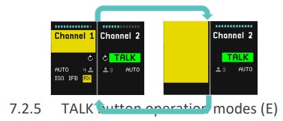 The TALK button offers three operation modes.
 AUTO, a double function:
– Push the TALK button momentarily, the TALK function is now latched on.
– Push the TALK button momentarily, the TALK function is now off.
– Push and hold the TALK button, the TALK function is active as long as the TALK button is held. When the TALK button is released the TALK function is switched off.- LATCH:
– Push the TALK button momentarily, the TALK function is now latched on.
– Push the TALK button momentarily, the TALK function is now off. - PUSH:
– Push and hold the TALK button, the TALK function is active if the TALK button is held. When the TALK button is released, the TALK function is switched off.
TALK button operation mode can be set using Q-Tool configuration software.
![]() If the operation mode is displayed in orange, quiet environment mode is active for the respective channel.
If the operation mode is displayed in orange, quiet environment mode is active for the respective channel.
7.2.6 ISO active indication (F) ![]()
The symbol ISO indicates an active Isolate function. When you activate the TALK button of a Channel with activated ISO function, you will only hear the users of that Channel. Audio from other Channels is muted to improve intelligibility of this particular channel you are talking to. The Program input is not muted.
7.2.7 IFB active indication (G) ![]()
The symbol IFB indicates an active interruptible foldback. The program input signal level is dimmed by the amount specified in a Role if someone is speaking on the Channel.
7.2.8 Audio receive indication (H) ![]()
The yellow RX indication is shown if audio is being received on the Channel.
7.2.9 Channel User Count (I) ![]()
Shows the number of users available on this channel. If the symbol is shown in red and indicating 1 user, you are the only user of this channel.
7.2.10 Replay available indication (K) ![]()
Replay indication will be shown if there is a recording present on that Channel.
Recorded messages can be replayed by pushing the replay button of the Channel.
![]() The last recorded message will be played back immediately The Channel display will show the replay status.
The last recorded message will be played back immediately The Channel display will show the replay status.![]()
The Speaker Station’s right display informs about how long ago each message was recorded and how long each recorded message is.
Start playback of each individual message by pressing buttons A to C.
The bottom line tells you which Channel the message was recorded from and indicates the volume setting. While playing back you may use the Channel volume encoder or the main rotary encoder to adjust the Channel volume.
![]() Pressing the Back button ends playback of recorded messages and returns to normal operation mode.
Pressing the Back button ends playback of recorded messages and returns to normal operation mode.
A long press on the Back button deletes all recorded messages.
![]() If message recording is disabled in Q-Tool, the replay available indication is crossed out.
If message recording is disabled in Q-Tool, the replay available indication is crossed out.
7.3 A/B/C/D button display
Public Announce, Talk to Many, Control and System functions can be assigned to buttons A to D and are shown in the right Speaker Station display. 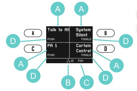 A Button function
B Partyline system device count
C Program Input indication
D Button operation mode
7.3.1 Public Announce, Talk to All and Talk to Many
The function can be activated by pressing the button near the quadrant.
The display will show a green TALK indication, or a red BUSY indication if someone else is already using this function. Once the other user disables his TALK function, your TALK will show green and you can start talking. 7.3.2 Control switching
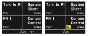
Control states can be changed from any device of a punQtum Q-Series digital partyline intercom system. If a Control has an active state, you will see a yellow ACT indicator. The state of control is made available to external devices through the General Purpose Outputs on the rear side.
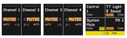
 7.3.3 System Mute function
System Mute disables all CALL and TALK functions and mutes all program input signals. It stays active as long as the button is pressed (PUSH behavior). An active System Mute is shown with an orange MUTED indicator.
 7.3.4 System Silent function
System Silent mutes the Q210P Speaker Station speaker and prevents any other punQtum devices from making sound. Public announcements remain functional, optical signaling when using a CALL function remains functional as well. The function is activated through a button push. Pressing the button again deactivates the function (TOGGLE behavior). An active System Silent is shown with an orange SILENT indicator.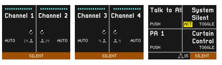
7.3.5 Partyline system device count ![]()
Shows the number of all units participating in your partyline intercom system. If the symbol is shown in red and indicating 1, your device is the only one in the system.
7.3.6 PGM indication![]()
The PGM symbol indicates a selected Program input. If the symbol is shown in white the Program input is received, if red, the selected Program input is not received.
Program inputs are only available if configured on a punQtum Q210P Speaker Station as part of the partyline system.
7.3.7 Button operation modes
Buttons assigned to Controls can have TOGGLE or PUSH behavior:
- TOGGLE: Any short press on any assigned button changes the state of the Control. If a Control has an active state, it will be shown with a yellow ACT indicator.
- PUSH: Pressing and holding an assigned button will activate the function until the button is released again.
Role and I/O setting define most of the settings for the user. Some of the items can be changed by the user via the Menu. If menu items are locked in Q-Tool for the active role, they are not displayed in the menu.
![]() Push the main rotary encoder to enter the Menu, turn it to navigate through the Menu, and push it to select an item.
Push the main rotary encoder to enter the Menu, turn it to navigate through the Menu, and push it to select an item.
![]() Use this button to step backwards or exit the Menu.
Use this button to step backwards or exit the Menu. 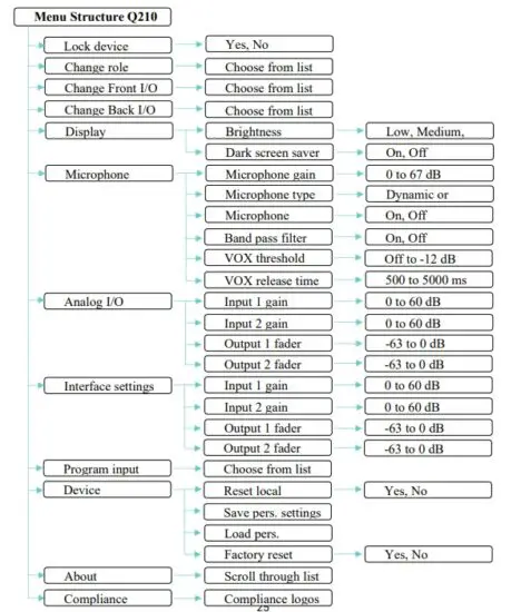 8.1 Lock device
 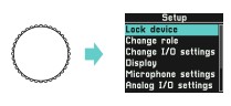 Role settings for your device may include an option to lock the front panel using a 4 digit pin.
The pin is defined per Role in Q-Tool configuration software.
The Lock device menu entry is only shown if the selected Role has an active lock front panel option.
Note that the factory default configuration does not include front panel locking.
To lock your device, select ‘Lock device’ and push the main rotary encoder to confirm. The microphone of your device will be muted and the lock screen is showing the name of the selected role: 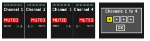 To unlock your device, enter the 4-digit pin using the main rotary encoder and confirm the unlock. The Back button allows scrolling back through the digits.
 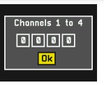 The backpanel connections of a Speaker Station continue working regardless of of the lock state of the device except for an analog output configured to ‘Ext Speaker’.
8.2 Change Role  You may change your active Role. Roles can be defined with the help of Q-Tool configuration software.
8.3 Change Front I/O settings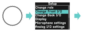 Select from different front panel I/O settings presets. Q-Tool configuration software allows to define more I/O settings to match the specifics of external devices connected to your Speaker
Station front panel.
8.4 Change Back I/O settings Select from different back panel I/O settings presets. Q-Tool configuration software allows to define more I/O settings to match the specifics of external devices connected to your Speaker Station back panel.
8.5 Display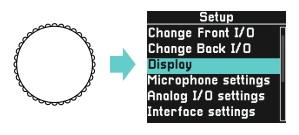 8.5.1 Brightness
  The display backlight can be varied in three steps and is stored on your device.
8.5.2 Dark screen saver  If the Dark screen saver is enabled, it will be activated automatically and deactivated by any button press or encoder turn. It will show a very low-brightness Q logo when active.
8.6 Microphone settings 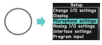
Microphone settings enable access to the settings predefined in the I/O settings and enables fine-tuning the settings according to your specific situation. Your settings will be stored on the device and are applied again when you power up your device.
8.6.1 Microphone gain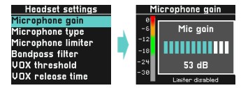 The gain of your microphone can be adjusted from 0 dB to 67 dB. Speak into your microphone at the volume you typically use when working and adjust the level to be in the upper green range.
Please note that the limiter function is temporarily set to off when setting the gain level.
8.6.2 Microphone type 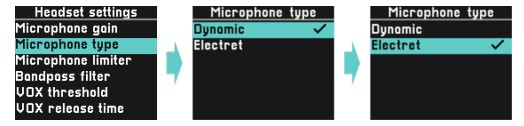 The limiter function is used to avoid distorted signals if someone gets excited and starts to speak more loudly. We recommend to set the limiter to on.
8.6.4 Band pass filter 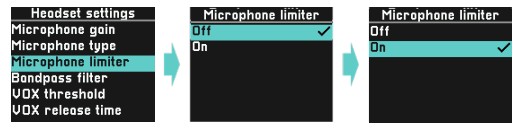 The Band pass filter removes lower and higher frequencies from your microphone signal to improve speech intelligibility. Activate it if needed.
8.6.5 Vox Threshold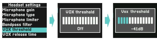 The Vox function acts as a signal gate and is used to reduce background noise in the system.
The Vox threshold level determines at which level an audio signal is passed on to the system.
Setting the Vox threshold to off completely removes the gate function from the signal path.
Make sure the level of your speech is higher than the VOX threshold level. Useable range is -63dB to -12dB
8.6.6 Vox Release 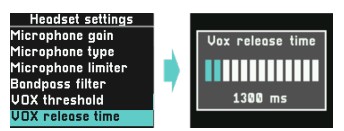 Vox release time determines how long your speech signal will be passed on to the system once the signal level goes below the VOX threshold level. This is used to avoid chopping your speech. VOX release time can be set from 500 milliseconds to 5 seconds in steps of 100 milliseconds.
8.7 Analog I/O settings
8.7.1 Analog Input
Adjust the gain of the backpanel analog inputs so the level is in the upper green range.
This overrides the settings that came with the I/O settings you chose for your Speaker Station.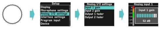 8.7.2 Analog output
Adjust the fader of the backpanel analog outputs according to your needs. This overrides the settings that came with the I/O settings you chose for your Speaker Station. 8.7.3 External Speaker Output
If one of your analog outputs is configured to ‘External Speaker Output’ you can adjust the maximum output level sent to your external speaker input, so it does not produce a distorted signal. Speaker volume is adjusted like described in 0 ![]()
Volume Button. This overrides the setting that came with the I/O settings you chose for your Speaker Station.  8.8 Interface settings
8.8.1 Interface Input Gain
Adjust the gain of the backpanel interface inputs so the level is in the upper green range. This overrides the settings that came with the I/O settings you chose for your Speaker Station. 8.8.2 Interface Output Level
Adjust the fader of the backpanel interface outputs according to your needs. This overrides the settings that came with the I/O settings you chose for your Speaker Station. 8.9 Program Input
 The Program inputs defined for your partyline system are listed here. You may select the Program input that suits your Role best. Selecting “No program” will switch off the Program input on your unit.
The Program volume can be controlled using the Volume button. See 0
8.10 Device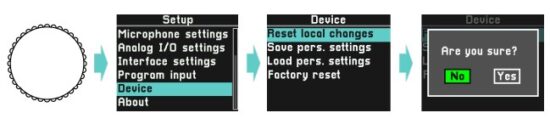
All current settings of your device are stored locally and applied again when powering up the evice.
8.10.1 Reset local changes
Use this entry to revert all settings to the values as set in the active Role and I/O setting. Volumes will be set to the default values.
8.10.2 Save personal settings
This will save your personal settings to a storage space on your unit that is NOT overwritten by a firmware or a system update. Personal settings include:
Microphone settings for each gooseneck and headset:
- Microphone gain
- Microphone type
- Bandpass Filter
- VOX threshold
- VOX release time
Volume settings:
- Master output speaker
- Master output headset
- Partyline fader for channels 1 to 4
- Sidetone fader
- Program fader
- Buzzer fader
Display settings:
- Brightness
- Screensaver
Backpanel audio settings:
- Analog I/O
o Input 1 & 2 gain
o Output fader 1 & 2 - Interface 1 & 2
o Input 1 & 2 gain
o Output fader 1 & 2
Previously saved Settings will be overwritten.
8.10.3 Load personal settings
This will restore your previously saved personal settings and instantly apply them.
8.10.4 Factory reset
The unit will be reset to the factory default settings.
Please note that your device will lose connection to your active partyline system unless it is the factory default system. Use Q-Tool to add a device to a system other than the factory default system.
8.11 About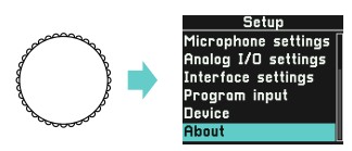 Get access to read-only information about your device. Scroll to access all available information:
 8.11.1 Device name
The default name of your device is derived from the unique MAC address of your device. Use Q-Tool to name the device differently. The given name will not be changed when applying a FW update. Resetting the device to factory default condition will also reset the device name.
8.11.2 IP address
This is the current IP address of your device.
8.11.3 Firmware version
This is the current firmware version. Use Q-Tool to retrieve and apply FW updates.
8.11.4 Hardware version
This is the hardware version of your unit. This value cannot be changed.
8.11.5 MAC address
This is the MAC address of your device. This value cannot be changed.
8.12 Compliance
Get access to read-only information about compliance marks of your device. 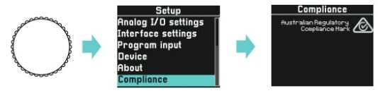
Q-Tool
Get your free copy of Q-Tool, the Q-series digital partyline configuration software, to enjoy the full features of your punQtum intercom. You may download it from the punQtum website www.punQtum.com.
Please read the Q-Tool manual for more information on the configuration with QTool.
10 Technical specifications
Technical specifications are in the Q210 P Speaker Station datasheet available from our website.
Documents / Resources
 |
PUNQTUM Q210PW Network Based Intercom System [pdf] User Manual Q210PW Network Based Intercom System, Q210PW, Network Based Intercom System, Based Intercom System, Intercom System, System |