Promitto 105005 Automatic LED Controller User Manual

Product information
Automatic, sensor-controlled lighting of the stairs. Let the light turn on automatically when you enter the stairs and automatically go out. Save electricity while always having the light where you need it – when you need it.
Package contains:
- 1 Controller
- 6 m Sensor cables
- 2 pcs IR-sensors
- 1 Power supply
- 1 User manual
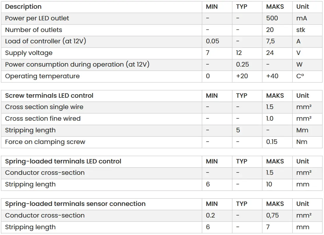
Specifications
![]() Used electrical and electronic products, including all types of batteries, must be delivered for recycling at a separate collection point. (acc. to directive 2012/19/EU and 2006/66/EC).
Used electrical and electronic products, including all types of batteries, must be delivered for recycling at a separate collection point. (acc. to directive 2012/19/EU and 2006/66/EC).
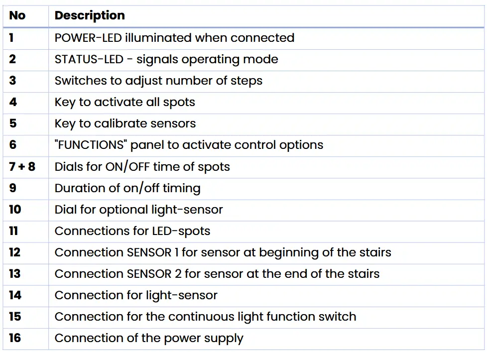
Overview
Please ensure that you have familiarized yourself with the manual before installing the device. This in particular applies to the chapter “Operating conditions and safety instructions” section 5.
Description of the control unit
This control unit enables the sensor-controlled switching on and off of your LED stair lighting. The effect can be easily adjusted via rotary control on the device top. An external continuous light switch as well as a twilight sensor can be connected to the control unit and thus round off the functional spectrum.
Thanks to the modular design of the control unit, the range of functions can also be expanded easily and cost-effectively.
The robust components, which are designed for the required size, as well as numerous integrated protective circuits of the control unit, ensure a safe and long-lasting operation. The high-quality DIN mounting rail housing according to DIN43880 permits safe and maintenance-free assembly directly in the house distribution.
A lot of value was also placed on ecological aspects. Through the use of high- quality components, the power consumption during operation is less than half a watt – including the HF sensors. The control unit is produced in Germany; of course, according to all the statutory standards and without the use of dubious materials. For example, the use of tantalum capacitors is completely dispensed with.
Components

Installation
If you are not sure about the correct connection or if questions arise which are not clarified by this manual, please contact us before commissioning!
Email: support@interactivefurniture.de
Installation of the sensors
The use of the enclosed indoor sensors makes it possible to detect people who are passing by and to activate the running light. For this purpose, a sensor is installed at the beginning, as well as at the end of the staircase. In contrast to an ordinary light barrier, motion detection is carried out exclusively from a stairway and thus also allows installation on single-sided open stairs. Reflectors or additional infrared transmitters / receivers are not required. The range of the sensor is about one meter.
In principle, two installation options are provided:
- Positioning of the sensor at the height of the first step: Installed such that the lighting is activated precisely when entering the staircase. If desired, the “Quick start” function (see section 3.6) can be used to switch on the first three LED outputs so that the steps in front of you are instantly illuminated.
- Positioning of the sensor approximately 50 cm in front of the stairs: When installed just before the staircase, the light is activated a moment before entering the staircase. This has the advantage that the first steps are already illuminated when entering the staircase and you do not walk into darkness.
Further installation instructions:
- The installation height must be selected in such a way that the sensor is always traversed and not stepped over. A guideline is about 20-50 cm above the ground / step.
- When mounting the sensors, ensure that they are installed horizontally with the sensor lenses to the opposite side of the staircase. This is the only way to ensure optimal recognition.
- The sensors automatically calibrate when the control unit is put into operation and thus adjust to the width of the staircase. This calibration is performed again at every start-up.
- The sensors should be protected against contamination and contact, since this would otherwise impair the function of the sensors.
- It is recommended to use the supplied sensor cable. It is not permissible to loop the sensor cable through multi-conductor cables – together with LED leads.
- If possible, the sensor cable should be laid separately from other cables (230 V) in order to avoid disturbances in motion detection.
Connecting the sensors
The bottom step sensor (LED- channel 1) should be wired to connection SENSOR 1, and the top step to SENSOR 2.
The colored markings of the supplied sensor cable must be connected to the control unit as well as to the sensor connection adapter as follows:
green = + (Power supply – 5V)
brown = – (Earth/GND)
white = S (sensor connection)
Connecting LED-illuminants
The connection leads of the LED illuminants are screwed on to the connection terminals located on top of the control unit. The polarity can be found in the graphic on page 4, as well as in the labelling on the control unit. The first LED spot at the beginning of the stair is connected to terminal 1 of the control unit – all further spots follow in the order in which they were installed.
The number of connected LEDs must be entered in the configuration of the control unit – see section 3.1. Please also provide for a sufficient dimensioning of the conductor cross-section of 0.5 mm2 or greater.
Connection of the twilight sensor
The control unit supports the connection of an external light sensor to deactivate the control by day (page 4). A polarity is not to be considered when connecting the twilight sensor. For information on configuring the twilight sensor, see page 10 of this manual.
CAUTION!
Not a potential-free connection! No voltage may be applied to these contacts!
Only the connection of the “interactive furniture twilight sensor” is envisaged.
Connecting the external switch for the continuous light function
The control unit supports the connection of an external switch or relay (for example, a relay actuator of a home automation system) to activate the continuous light function (page 4). When the “ON” and “GND” contacts are connected, all connected LED illuminants are activated and remain active until the connections are disconnected. The sensor-controlled automatic is out of operation in this mode. When the continuous light function is activated, the green “STATUS” LED is lit continuously. See section 3.9.
CAUTION!
Not a potential-free connection! No voltage may be applied to these contacts!
Only the connection of the contacts via a switch is envisaged.
Connecting the power supply
The supply voltage (maximum 24V-DC) of the control unit is connected to the contact 16 of the overview graphic on page 4. The left plus pole supplies the control unit itself as well as the LED channels 1 to 10 -the right plus pole the LED channels 11 to 20. This allows – for the distribution of the connection load – the use of two separate power supplies (Attention: the Minus pole is internally pressed). The polarity can be found in the graphic on page 4 as well as in the labelling on the control unit.
IMPORTANT:
- The supply voltage must be selected in accordance with the connected LED illuminants, since these can otherwise be damaged. Example: A 12V power supply has to be used for 12V LED strips.
- The supply voltage must not exceed 24 V (direct current).
- Use a power supply unit with sufficiently dimensioned output power.
- Make sure that the power supply is connected to the correct polarity.
- Connect both minus and both positive poles with the power supply unit, as otherwise the LEDs 11-20 are not supplied with voltage.
ATTENTION – DANGER TO LIFE!
NEVER connect the control unit directly to the 230V power supply!
Correct use of the connection terminals
LED control – LED outputs: Single and fine-wire cables with a cross-section of max. 1.5 mm2 can be used. We recommend the use of wire-end terminals – otherwise, isolate the cable over a length of 5 mm. Feed the cable into the screw terminal and screw it. Subsequently check the cable for a firm hold.
LED control – spring-loaded terminals: Single- and fine-wire cables with a cross- section of max. 1.5 mm2 can be used. Isolate the cable to a length of 6 to 10 mm and insert it into the spring-loaded terminal. To close the spring clamp, simply move the eccentric lever downwards. Subsequently check the cable for a firm hold.
Sensor connection adapter: Single and fine-wire cables with a cross-section of 0.2 to 0.75 mm2 can be used. Isolate the sensor connection cables to a length of 6-7 mm. The terminals on the sensor connection adapter can be opened by applying low pressure to the actuation press-ins – use the supplied tool. Insert the cables into the terminals. Subsequently check the cable for a firm hold in the terminal.
Configuration of the control unit
This section outlines the configuration options for the control unit. Please ensure that you have read the following information before starting up the control unit.

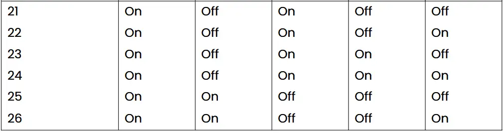
Entering number of stairs (STEPS)
The number of illuminated steps is entered using five switches (“STEPS”) on the control unit (page 4, no. 3). All further channels of the control serve the ambient lightning function (see 4.1).
Please refer to the following table for the correct switch positions:

Calibrating the on and off switching speed
The speed of the switching on and off process of the light-emitting diodes can be adjusted separately with the “ON SPEED” and “OFF SPEED” controllers.
Turning the control dial “ON SPEED” in a counter clockwise direction slows the switching on speed of the LED-illuminants down to a maximum of one second per spotlight. When turned clockwise, this can be sped up this process to a minimum of 20 milliseconds per spotlight. The change in the “OFF SPEED” controller has an analog effect on the switch-off speed of the connected LEDs.
Calibrating of the pause between the switch-on and switch-off process
The “DELAY” slider is used to set the pause between the switch-on and the switch- off process. In this case, it is possible to select continuously between half a second (stop on the left) and about one minute (stop on the right).
Activation and calibration of the twilight sensor
If a twilight sensor is connected to the control unit, it is activated and adjusted via the “LIGHT” control. In the stop on the left the twilight sensor is completely deactivated and the automatic remains switched on even in daylight. When rotated clockwise, the light-automatic switches on only when darkness increases. The “STATUS” LED goes out if the brightness value is exceeded and the automatic is thus deactivated. A blinking of the “STATUS” LED when the twilight sensor is activated indicates that the threshold value is below the threshold – the automatic is activate.
Important: Two minutes after activation of the control unit, this value is saved and from this point onwards only readjusts every 30 seconds. By using the RESET- switch the threshold value can be calibrated for a further two minutes. This function prevents the operating mode from changing “involuntarily” when the brightness changes briefly.
Function “1st step illumination”
With the switch 1 of the “FUNCTIONS”- switch panel the first and last LED-spot are switched on in a dimmed mode to illuminate the beginning of the staircase. The optional twilight sensor switches off the 1st step illumination during daytime.
Function “Quick Start”
In many installation situations it is not possible to place the motion sensor in front of the staircase. It can thereby it can happen that you enter the stairs with the first steps still unlit, with the lighting only subsequently catching up from the rear.
To prevent this, we have the developed the “Quick Start”-feature: The first stages are activated in increased speed for instant illumination. The switch 2 of the “FUNCTIONS”-panel activates this feature.
RESET-key
Pressing the RESET-key recalibrates the sensors. This becomes necessary if the setting on the sensors and control changes. This also occurs after each interruption of the control voltage supply.
TEST-key
By pressing the TEST-key, all connected LED-illuminants are activated.
Status-LEDs
To indicate the operation status of the control device, two LEDs are positioned in the front of the case (page 4, no. 1 and 2). As soon as the controller is connected to power, the red LED lights up. If this does not occur, disconnect the device immediately (see 4.2).
Additionally, the green STATUS-LED ashes each second and thereby signals the activity of the sensors. If the twilight function is activated, the green LED is illuminated constantly (see 2.5). If the twilight sensor function is activated and the brightness threshold is exceeded, the STATUS-LED stops and thereby signals that the automated mode is deactivated.
Further hardware features
Ambient lightning
The unused LED-channels (maximum 4, in the case of 10 steps, the LED-channels 11 up to 14) can be used for an additional, general illumination of the staircase. These channels are concomitantly dimmed on entering the staircase, and then disengaged with the last step – optimally suited for LED-stripes in the banister or additional spots in the ceiling.
The optional twilight sensor deactivates the ambient lightning channel during daytime.
Internal fuses
Three fuses are installed to protect the control unit against short circuits at the sensor inputs or cables, exceeding of the maximum load of the control unit, incorrect installation, or a fault in the electronics. If the POWER-LED is not active while the unit is connected to the power grid, this indicates a blown fuse.
In this case the controller should be disconnected from the power supply immediately. The necessary electronics check and fuse replacement should only be performed by the manufacturer or a qualified professional.
Connecting cables should also be checked for defects, as well as the power supply for faults (Polarity reversal, wrong voltage).
Furthermore, every LED-output is secured with an additional 750mA resettable fuse. In case of a short circuit, this prevents the destruction of the control unit.
Bus connections
On the bottom side of the device, a bus system connector is installed to allow extension with additional modules. Please ensure that these contacts are neither short-circuited nor contaminated.
Further information
Correct usage
The control device is intended to be used for the activation 10V-24V LED- illuminants triggered by two infrared sensors connected to the device. Any other use is not covered by the terms of warranty.
Operating conditions and safety instructions
If there is any safety risk during operation the system should be deactivated and protected against unintentional reactivation.
This applies to:
- if the device shows visible signs of damage,
- if the device no longer functions,
- if a piece of the device is loose or no longer properly attached
- if the connecting cables show visible damage
The device should only be repaired by a qualified professional.
- Before opening the device, always ensure that it has been unplugged from the power supply. Power must be disconnected during installation.
- It has in principle to be checked whether the device is appropriate for the intended purpose and location before beginning installation. If uncertain it is recommended to consult a qualified professional or the manufacturer.
- Power conducting cables and wiring connected to the device should always be inspected for damaged insulation and breakages. If any wiring faults are detected, the device should be switched off immediately until the problem has been fixed.
- For reasons of safety and certification (CE), unauthorized alternations and modifications are not permitted.
- The acceptable ambient temperature (room temperature) during operation may not exceed or fall below the temperature range between 0°C and 40°C . If the temperature falls below the minimum operating threshold this can impair the fuse function and may damage the device in the case of a short circuit.
- The device is designed to operate in dry and clean environments. Use of the device outdoors or in damp rooms is not permitted.
- Protect the device and in particular the sensors from moisture, water splashes and heat sources like direct sunlight.
- The device should not be used in connection with easily flammable and combustible liquids. Do not operate the unit in an environment in which combustible gases, vapours or dusts are or may be present.
- The device, components and packaging do not belong in children’s hands.
- The device should only be commissioned under the supervision of a trained professional or other qualified person.
- In commercial or public buildings, the device should be installed in accordance with national electrical accident prevention regulations.
- Ensure cables are installed so as not to cause accidents.
- If the device is no longer in use, it should always be disconnected from the power supply.
Disposal instructions
If the appliance has reached the end of its service life, take the old appliance to the collection point of your municipal waste disposal carrier. The control unit must not be disposed of via household waste.
Warranty and liability
This device comes with a three year warranty. The warranty covers free repair of defects which can be proven to result from defective materials or errors during manufacture.
We accept neither responsibility nor liability for direct or indirect damage in connection with this product.
We reserve the right to offer either repair, correction, delivery of a replacement or refund of the purchase price. Further reaching claims are excluded.
Interactive Furniture will not be held liable for operating and installation errors beyond our control. The warranty is deemed void and repair will not be carried out under the following circumstances:
- incorrect installation of the control unit
- alterations to the device or attempted repairs
- destruction of the warranty seal
- overloading of the device
- operation outside of the recommended operating temperature range
- damage due to inattention to operating instructions
- connection of incorrect voltage or power type
- incorrect polarisation of the device
- incorrect operation or damage from negligent use or misuse
- defects due to bridged or incorrectly installed fuses
Promitto Group AS | Fløisbonnveien 5 | NO – 1412 Sofiemyr | www.promitto.group
Documents / Resources
 |
Promitto 105005 Automatic LED Controller [pdf] User Manual 105005 Automatic LED Controller, 105005, Automatic LED Controller, LED Controller, Controller |