PPI ScanLog 96 Single Dual Channels Universal Process Data Logger with PC Software

This brief manual is primarily meant for quick reference to wiring connections and parameter searching. For more details on operation and application; please log on to www.ppiindia.net
OPERATOR PARAMETERS
| Parameters | Settings |
| Batch Start | No Yes |
| Batch Stop | No Yes |
ALARM SETTINGS
| Parameters | Settings (Default Value) |
| Select Channel (Available only for Dual Channel Version) | 1 or 2 |
| Select Alarm | AL1, AL2, AL3, AL4
(The actual available options depends on the numbers of Alarms set per channel on Alarm configuration page) |
| ALx Type
x = 1, 2, 3 or 4 |
None Process Low Process High (Default : None) |
| ALx Setpoint
x = 1, 2, 3 or 4 |
Min. to Max. of selected input type range
(Default : 0) |
| ALx Hysteresis
x = 1, 2, 3 or 4 |
1 to 30000
(Default : 20) |
| ALx Inhibit
x = 1, 2, 3 or 4 |
No Yes
(Default : No) |
DEVICE CONFIGURATION
| Parameters | Settings (Default Value) |
| Scan Rate | 1 Sec. to 99 Sec. (Default : 3 Sec.) |
| Delete Records | No Yes
(Default : No) |
| Recorder ID | 1 to 127
(Default : 1) |
CHANNEL CONFIGURATION
| Parameters | Settings (Default Value) |
| Select Channel (This parameter is available for Dual
Channel Version only) |
1 or 2 |
| Input Type | Refer Table 1
(Default : 0 to 10 V) |
| Resolution | Refer Table 1 |
| Parameters | Settings (Default Value) | ||||||||||||||||||||||||
| Units | Refer Table 2 (Default : °C) | ||||||||||||||||||||||||
| Signal Low |
|
||||||||||||||||||||||||
| Signal High |
|
||||||||||||||||||||||||
| Range Low | -30000 to +30000
(Default : 0.0) |
||||||||||||||||||||||||
| Range High | -30000 to +30000
(Default : 1000) |
||||||||||||||||||||||||
| Low Clipping | Disable Enable
(Default : Disable) |
||||||||||||||||||||||||
| Low Clip Val | -30000 to High Clip Val (Default : 0) | ||||||||||||||||||||||||
| High Clipping | Disable Enable
(Default : Disable) |
||||||||||||||||||||||||
| High Clip Val | Low Clip Val to 30000 (Default : 1000) | ||||||||||||||||||||||||
| Zero Offset | -30000 to +30000
(Default : 0) |
ALARM CONFIGURATION
| Parameters | Settings (Default Value) |
| Alarms/Chan | 1 to 4
(Default : 4) |
| Relay-1 Logic Relay-2 Logic | Normal Reverse (Default : Normal) |
RECORDER CONFIGURATION
| Parameters | Settings (Default Value) |
| Normal Interval | 0:00:00 (H:MM:SS) to
2:30:00 (H:MM:SS) (Default : 0:00:30) |
| Zoom Interval | 0:00:00 (H:MM:SS) to
2:30:00 (H:MM:SS) (Default : 0:00:10) |
| Alrm Toggl Rec | Disable Enable
(Default : Enable) |
| Recording Mode | Continuous Batch
(Default : Continuous) |
| Batch Time | 0:01 (HH:MM) to
250:00 (HHH:MM) (Default : 1:00) |
| Batch Start Batch Stop | No Yes |
RTC SETTING
| Parameters | Settings |
| Time (HH:MM) | 0.0 to 23:59 |
| Date | 1 to 31 |
| Month | 1 to 12 |
| Year | 2000 to 2099 |
UTILITIES
| Parameters | Settings (Default Value) |
| Lock Unlock | No Yes
(Default : No) |
| Factory Default | No Yes
(Default : No) |
| TABLE – 1 | ||
| Option | Range (Min. to Max.) | Resolution & Unit |
| Type J (Fe-K) | 0.0 to +960.0°C / +32.0 to +1760.0°F |
1 °C /°F or 0.1 °C /°F |
| Type K (Cr-Al) | -200.0 to +1376.0°C / -328.0 to +2508.0°F | |
| Type T (Cu-Con) | -200.0 to +387.0°C / -328.0 to +728.0°F | |
| Type R (Rh-13%) | 0.0 to +1771.0°C / +32.0 to +3219.0°F | |
| Type S (Rh-10%) | 0.0 to +1768.0°C / +32.0 to +3214.0°F | |
| Type B | 0.0 to +1826.0°C / +32.0 to +3218.0°F | |
| Type N | 0.0 to +1314.0°C / +32.0 to +2397.0°F | |
| Reserved for customer-specific Thermocouple types not listed above. The type shall be specified in accordance with the ordered (optional on request) Thermocouple type. | ||
|
RTD Pt100 |
-199 to +600 °C / -328 to +1112 °F
or -199.9 to +600.0 °C / -328.0 to +1112.0 °F |
1°C
or 0.1 °C |
| 0 to 20 mA |
-30000 to 30000 units |
1 Unit 0.1 Unit 0.01 Unit 0.001 Unit |
| 4 to 20 mA | ||
| 0 to 80 mV | ||
| Reserved | ||
| 0 to 1.25 V |
-30000 to 30000 units |
|
| 0 to 5 V | ||
| 0 to 10 V | ||
| 1 to 5 V | ||
| TABLE – 2 | |
| Option | Description |
| °C | Degree Centigrade |
| °F | Degree Fahrenheit |
| (none) | No Unit (Blank) |
| °K | Degree Kelvin |
| EU | Engineering Units |
| % | Percentage |
| Pa | Pascals |
| Mpa | Mpascals |
| kPa | Kpascals |
| Option | Description |
| bar | Bar |
| mbar | Milli bar |
| psi | PSI |
| kg/sq.cm | kg/cm² |
| mmH2O | mm water gauge |
| inH2O | Inches water gauge |
| mmHg | mm mercury |
| Torr | Torr |
| litre/hr | Litres per hour |
| litre/min | Litres per minute |
| %RH | % Relative Humidity |
| %O2 | % Oxygen |
| %CO2 | % Carbon di-oxide |
| %CP | % Carbon Potential |
| V | Volts |
| A | Amps |
| mA | Milli Amps |
| mV | Milli Volts |
| ohm | Ohms |
| ppm | Parts per million |
| rpm | Revolutions per minute |
| mSec | Milli seconds |
| Sec | Seconds |
| min | Minutes |
| hrs | Hours |
| PH | PH |
| %PH | %PH |
| miles/hr | Miles per hour |
| mg | Milli grams |
| g | Grams |
| kg | Kilo grams |
FRONT PANEL DISPLAY & KEYS
| Symbol | Key | Function |
 |
SET-UP | Press to enter / exit Set-up Mode. |
 |
DOWN | Press to decrease the parameter value. Pressing once decreases the value by one count; holding the key pressed speeds up the change. |
 |
UP | Press to increase the parameter value. Pressing once increases the value by one count; holding the key pressed speeds up the change. |
|
|
ENTER / Alarm ACK |
Press to store the set parameter value and to scroll to the next parameter in Set-up Mode.
Press to acknowledge / mute alarm output (if active). |

SCROLLING THROUGH VARIOUS SCREENS

AUTO/MANUAL SCAN MODE SELECTION
Press ENTER key for approximately for 5 Seconds to toggle between Auto & Manual Scan Mode. In Manual Mode use UP / DOWN Keys to Select Channels.
ELECTRICAL CONNECTIONS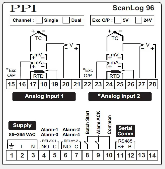
Notes:
- Analog Input 2 connections (terminals 23 to 28) are applicable only for Dual Channel version.
- Excitation Voltage output (terminals 15 & 22) is available optionally.
- Serial Commutation Port (terminals 11 & 12) is available for PC Interface Version only
101, Diamond Industrial Estate, Navghar, Vasai Road (E), Dist. Palghar – 401 210.
Sales : 8208199048 / 8208141446
Support : 07498799226 / 08767395333
E: sales@ppiindia.net, support@ppiindia.net
Documents / Resources
 |
PPI ScanLog 96 Single Dual Channels Universal Process Data Logger with PC Software [pdf] Instruction Manual ScanLog 96, ScanLog 96 Single Dual Channels Universal Process Data Logger with PC Software, Single Dual Channels Universal Process Data Logger with PC Software, Universal Process Data Logger with PC Software, Process Data Logger with PC Software, Data Logger with PC Software |
 |
PPI ScanLog 96 Single-Dual Channels Universal Process Data Logger [pdf] User Manual ScanLog 96 Single-Dual Channels Universal Process Data Logger, ScanLog 96, Single-Dual Channels Universal Process Data Logger, Universal Process Data Logger, Process Data Logger, Data Logger, Logger |