PORTUGAL MC80 Control Board for Loading Platforms
Product Usage Instructions
- This product is certified by European Community (EC) safety standards and complies with Directive 2011/65/EU.
- Always handle batteries, packaging, and electronic accessories with caution to avoid electric shock.
- The MC80 is an electronic control board for automating dock levelers.
FAQ
- Q: Is the product compatible with different voltage inputs?
- A: The product is designed to operate at three-phase 380Vac for the main power input and 24Vdc for control purposes. Ensure proper voltage compatibility before use.
- Q: What safety standards does the product comply with?
- A: The product is certified under European Community (EC) safety standards and complies with Directive 2011/65/EU.
SAFETY INSTRUCTIONS
| This product is certified by the European Community (EC) safety standards. | |
|
|
This product complies with Directive 2011/65/EU of the European Parliament and of the Council, of 8 June 2011, on the restriction of the use of certain hazardous substances in electrical and electronic equipment and with Delegated Directive (EU) 2015/863
from Commission. |
 |
(Applicable in countries with recycling systems). This marking on the product or literature indicates that the product and electronic accessories (eg. Charger, USB cable, electronic material, controls, etc.) should not be disposed of as other household waste at the end of their useful life. To avoid possible harm to the environment or human health resulting from the uncontrolled disposal of waste, separate these items from other types of waste and recycle them responsibly to promote the sustainable reuse of material resources. Home users should contact the dealer where they purchased this product or the National Environment Agency for details on where and how they can take these items for environmentally safe recycling. Business users should contact their vendor and check the terms and conditions of the purchase agreement. This product and its electronic accessories should not be mixed with other commercial waste. |
 |
This marking indicates that batteries should not be discarded like other household waste at the end of their useful life. Batteries must be delivered to selective collection points for recycling. |
 |
The different types of packaging (cardboard, plastic, etc.) must be subject to selective collection for recycling. Separate packaging and recycle it responsibly. |
 |
This marking indicates that the product and electronic accessories (eg. charger, USB cable, electronic material, controls, etc.) are susceptible to electric shock by direct or indirect contact with electricity. Be cautious when handling the product and observe all safety procedures in this manual. |
GENERAL WARNINGS
- This manual contains very important safety and usage information. Read all instructions carefully before beginning the installation/usage procedures and keep this manual in a safe place so that it can be consulted whenever necessary.
- This product is intended for use only as described in this manual. Any other enforcement or operation that is not mentioned is expressly prohibited, as it may damage the product and put people at risk causing serious injuries.
- This manual is intended firstly for specialized technicians and does not invalidate the user’s responsibility to read the “User Norms” section to ensure the correct functioning of the product.
- The installation and repair of this product may be done by qualified and specialized technicians, to ensure every procedure is carried out under applicable rules and norms. Nonprofessional and inexperienced users are expressly prohibited of taking any action unless explicitly requested by specialized technicians to do so.
- Installations must be frequently inspected for unbalance and the wear signals of the cables, springs, hinges, wheels, supports, and other mechanical assembly parts.
- Do not use the product if it is necessary repair or adjustment is required.
- When performing maintenance, cleaning, and replacement of parts, the product must be disconnected from the power supply. Also including any operation that requires opening the product cover.
- The use, cleaning, and maintenance of this product may be carried out by any persons aged eight years old and over and persons whose physical, sensorial or mental capacities are lower, or by persons without any knowledge of the product, provided that these are supervision and instructions given by persons with experience in terms of usage of the product in a safe manner and who understands the risks and dangers involved.
- Children shouldn’t play with the product or opening devices to avoid the motorized door or gate from being triggered involuntarily.
- If the power cable is damaged, it must be replaced by the manufacturer, after-sales service, or similarly qualified personnel to avoid danger.
- The device must be disconnected from the electrical network when removing the battery.
- Ensure that blocking is avoided between the actuated part and its fixed parts due to the opening movement of the actuated part.
WARNINGS FOR TECHNICIANS
- Before beginning the installation procedures, make sure that you have all the devices and materials necessary to complete the installation of the product.
- You should note your Protection Index (IP) and operating temperature to ensure that is suitable for the installation site.
- Provide the manual of the product to the user and let them know how to handle it in an emergency.
- If the automatism is installed on a gate with a pedestrian door, a door locking mechanism must be installed while the gate is in motion.
- Do not install the product “upside down” or supported by elements do not support its weight. If necessary, add brackets at strategic points to ensure the safety of the automatism.
- Do not install the product in an explosive site.
- Safety devices must protect the possible crushing, cutting, transport, and danger areas of the motorized door or gate.
- Verify that the elements to be automated (gates, door, windows, blinds, etc.) are in perfect function, align,d, and level. Also, verify if the necessary mechanical stops are in the appropriate places.
- The control board must be installed in a safe place of any fluid (rain, moisture, etc.), dust, and pests.
- You must route the various electrical cables through protective tubes, to protect them against mechanical exertions, essentially on the power supply cable. Please note that all the cables must enter the control board from the bottom.
- If the automatism is to be installed at a height of more than 2,5m from the ground or other level of access, the minimum safety and health requirements for the use of work equipment workers at the work of Directive 2009/104/CE of European Parliament and of the Council of 16 September 2009.
- Attach the permanent label for the manual release as close as possible to the release mechanism.
- Disconnect means, such as a switch or circuit breaker on the electrical panel, must be provided on the product’s fixed power supply leads under the installation rules.
- If the product to be installed requires a power supply of 230Vac or 110Vac, ensure that the connection is to an electrical panel with a ground connection.
- The product is powered by low voltage with a control board (only at 24V motors).
- Parts/products weighing more than 20 kg must be handled with special care due to the risk of injury. It is recommended to use suitable auxiliary systems for moving or lifting heavy objects.
- Pay special attention to the danger of falling objects or uncontrolled movement of doors/gates during the installation or operation of this product.
WARNINGS FOR USERS
- Keep this manual in a safe place to be consulted whenever necessary. If the product has contact with fluids without being prepared, it must immediately disconnect from the power supply to avoid short circuits, and consult a specialized technician.
- Ensure that the technician has provided you with the product manual and informed you how to handle the product in an emergency.
- If the system requires any repair or modification, unlock the automatism, turn off the power, and do not use it until all safety conditions have been met.
- In the event of tripping of circuit breakers of fuse failure, locate the malfunction and solve it before resetting the circuit breaker or replacing the fuse. If the malfunction is not repairable by consult this manual, and contact a technician.
- Keep the operation area of the motorized gate free while the gate in in motion, and do not create strength to the gate movement.
- Do not perform any operation on mechanical elements or hinges if the product is in motion.
RESPONSIBILITY
- Supplier disclaims any liability if:
- Product failure or deformation results from improper installation use or maintenance!
- Safety norms are not followed in the installation, use and maintenance of the product.
- Instructions in this manual are not followed.
- Damage is caused by unauthorized modifications
- In these cases, the warranty is voided.
MOTORLINE ELECTROCELOS SA.
- Travessa do Sobreiro, nº29 4755-474 Rio Côvo (Santa Eugénia) Barcelos, Portugal
SYMBOLS LEGEND
 Important safety notices
 Useful information
 Programming information
 Potentiometer information
 Connectors information
 Buttons information
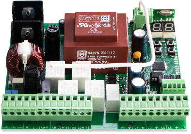
CONTROL BOARD
TECHNICAL CHARACTERISTICS
- The MC80 is an electronic control board for automating dock leveler.
| • Power | Three-phase 380Vac |
| • Output for motor | 380Vac 1500W Max. |
| • Output for auxiliary accessories | 24Vdc 12W Max. |
| • Fuse F1/F2/F3 | 10A |
| • Fuse F4 | 125mA |
| • Working Temperature | -25°C to +55°C |
| • Control board dimension | 198×134 mm |

CONNECTOR LEGEND

V+ |
Power input for traffic lights and buzzer 24vdc max. 200ma. |
| GI | Open collector connection for internal traffic light green light 24vdc max. 200ma. |
| RI | Open collector connection for internal traffic light red light 24vdc max. 200ma. |
| GO | Open collector connection for external traffic light green light 24vdc max. 200ma. |
| RO | Open collector connection for external traffic light green light 24vdc max. 200ma. |
| BU | Open collector connection for buzzer 24vdc max. 200ma. |

| Supply | Three-phase 380V input for powering the motor as well as the transformer for the digital part |
| Motor | Output for three-phase motor up to 1500W |
| Earth | Connecting the motor ground cables and power input |
|
Inter |
Interlock door:
The “ interlock door” output can be integrated into the door control stop circuit. The contact is opened in the case of: – The dock leveler is not in the initial position. – The dock leveler power failure. – Emergency shutdown. |
CONNECTOR LEGEND
| Pulse | IMPULS CLOSE: The “ impulse close” output can be applied in the case of a door with automatic closing or if you want additional security so that the door is never closed with the dock leveler out of its initial position.
The contact is opened while the dock leveler is being operated or is out of its initial position. The contact is closed whenever the dock leveler reaches the initial position. |
|
| Lamp | A light indicator will be placed on the front panel of the control board. | |
| Lights up for 500ms x1 waits 2sec. | Whenever the emergency push button is activated. | |
| Lights up for 500ms x2 waits 2sec. | Whenever a phase failure is detected. This error remains until a button is pressed. | |
| Lights up for 500ms x3 waits 2sec. | Whenever a wrong phase sequence is detected. This error remains until a button is pressed. | |
| Lights up for 500ms x4 waits 2sec. | Whenever current above the defined limit is detected. This error remains until a button is pressed. | |
| Lights up for 500ms x6 waits 2sec. | If the DOOR input is activated and its status changes to error. This error remains until a button is pressed. | |
| Lights up for 500ms x6 waits 2sec. | If the VEH input is selected as WheelBlock and it is activated. This error remains until a button is pressed. | |
| LIP-CL | Output for lip solenoid valve CLOSING | |
| LIP-OP | Output for lip solenoid valve OPENING | |
| LEVELLER | Output for dock leveler solenoid valve | |
| POWER 24V+ | 24V output for external accessories | |
| SLIP | Lip limit switch sensor in the initial position. NC Circuit | |
| SLEV | Dock leveler limit switch sensor in the initial position. NC Circuit | |
| VEH | Vehicle sensor. The vehicle detector recognizes that the truck is in the correct position and signals this optically and acoustically. Any type of sensor that has dry contact can be used and can be NC or NO. The sensor input logic can be changed in parameterization. The operating mode can be chosen in parameterization. | |
|
DOOR |
Open door position sensor input. Different types of sensors can be used as long as it is dry contact. The sensor contact mode can be changed in parameterization as well as its functionality. |
| OLIP | Connection for lip opening button |
| CLIP | Connection for lip closing button |
| BLEV | Connecting the button to open the dock leveler |
| STOP | Normally closed button for connecting an external emergency button causes the entire system to be turned off |
| FUNC | Connection for auto return/confirmation button |
OPERATING MODE
- To be able to access the menu, the dock leveler must be in standby mode or in a floating position!
 |
MENU NAVIGATION |
| 01 • Press the MENU button once.
02 • Select the menu you want to program with the UP and DOWN buttons. 03 • Press the MENU button once to enter the menu. 04 • Select the submenu you want to program with the UP and DOWN buttons. 05 • Press the MENU button once to edit the parameter value. 06 • Select the value you want to program with the UP and DOWN buttons. 07 • To save the chosen value, press the MENU button for one second. The display will flash to indicate that the value has been changed. |
To be able to access the menu, the dock leveler must be in standby mode or in a floating position!
- To go back, press the UP and DOWN buttons at the same time.
- If you do not press any button for 10 seconds, the control board will return to standby.
WITH HINGED LIP WITHOUT AUTOMATIC RETURN
- Pressing BLEV dock leveler push button, will activate the motor relay and the solenoid valve relay in human presence operation mode, then raise the dock leveler.
- The operator must press BLEV until the lip is extended, once it is, the BLEV button can be released and the motor relay will be turned off. The dock leveler must be raised at least during the time (M1-T1).
- The dock leveler then automatically lowers to the docking edge of the vehicle (floating position).
No auto return
- Press the BLEV button, activating the motor pump relay and solenoid valve relay until it is completely folded.
- Release the BLEV button and the motor pump relay is switched off.
- The dock leveler automatically lowers to the initial position.
- After the time (M1-T5) the dock leveler is in the initial position or SLEV is detected.
WITH HINGED LIP WITH AUTOMATIC RETURN
- Pressing BLEV dock leveler push button, will activate the motor pump relay and the solenoid valve relay in human presence operation mode, then raise the dock leveler.
- The operator must press BLEV until the lip is extended, once it is, the BLEV button can be released and the motor pump relay will be turned off. The dock leveler must be raised at least during the time (M1-T1).
- The dock leveler then automatically lowers to the docking edge of the vehicle (floating position).
Automatic return
- Press the FUNC button for 1 second.
- The dock leveler is raised by time (M1-T3) activating the motor pump relay and solenoid valve relay.
- As soon as the time (M1-T3) reaches the end, the motor pump relay turns off.
- The dock leveler automatically lowers to the initial position.
- After the time (M1-T5) the dock leveler is in the initial position or SLEV is detected.
WITH EXTENDABLE LIP WITH AUTOMATIC RETURN
Pressing BLEV dock leveler push button, will activate the motor pump relay and the solenoid valve relay in human presence operation mode, then raise the dock leveler. The dock leveler must be raised for at least the time (M1-T1).
After reaching the ideal position, the dock leveler can be stopped, so the user can release the BLEV push button, disconnecting the motor pump relay as well as the solenoid valve relay. The dock leveler will remain in this position for 5 seconds and during this time the lip must be positioned using the OLIP button. If no button is pressed, the dock leveler drops back to the initial position, activating the solenoid valve relay.
The lip can be positioned with the buttons out in the Human Presence operating mode using the OLIP button, activating the motor pump relay as well as the LIP-OP relay. The lip must be expelled for at least the minimum lip exit time (M2-T1). If the time (M2-T2) ‚ is reached, the lip stops automatically, turning off the LIP-OP > MOTOR relay and activating the solenoid valve relay. After releasing the OLIP button and turning off the LIP-OP relay > MOTOR and activating the solenoid valve relay, the dock leveler automatically lowers to the docking edge of the vehicle (floating position)
Automatic return
- Press the FUNC button for 1 second.
- The dock leveler is raised by time (M1-T3) activating the motor pump relay and solenoid valve relay.
- When reaching the value of (M1-T3) the solenoid valve relay is turned off.
- The lip is retracted over time (M2-T3) activating the LIP-CL.
- Upon reaching the value of (M2-T3) the LIP-CL relay is turned off.
- The dock leveler is raised by time (M1-T4) activating the solenoid valve relay.
- When this value of (M1-T4) is reached, the solenoid valve relay is turned off.
- The lip is completely retracted by activating the LIP-CL relay until it reaches the SLIP limit switch or when it reaches the time of (M2-T4) if SLIP is not used.
- Upon reaching this value of (M2-T4) or SLIP, the LIP-CL relay is turned off.
- The dock leveler lowers automatically, activating the solenoid valve relay to the initial position.
- When reaching the SLEV sensor or reaching the time (M1-T5) the motor pump relay is switched off.
PROGRAM
M FUNCTIONS

M FUNCTIONS


DISPLAY
DISPLAY INDICATIONS

CONNECTION DIAGRAM
WITH HINGED LIP WITHOUT AUTOMATIC RETURN


WITH EXTENDABLE LIP WITH AUTOMATIC RETURN

Documents / Resources
 |
PORTUGAL MC80 Control Board for Loading Platforms [pdf] Instruction Manual MC80 Control Board for Loading Platforms, MC80, Control Board for Loading Platforms, Board for Loading Platforms, Loading Platforms |