![]()
Probing Solutions.
Made in Germany.

KSZ 100 D
Calibration Generator for Current Probes
20 A to 100 A
Instruction Manual
Copyright © 2021 PMK – All rights reserved.
Manufacturer
PMK Mess- und Kommunikationstechnik GmbH
Koenigsteinerstrasse
98 65812 Bad Soden am Taunus, Germany
Phone: +49 (0) 6196 5927 – 930 Fax: +49 (0) 6196 5927 – 939
Internet: www.pmk.de E-Mail: sales@pmk.de
Warranty
PMK warrants this product for normal use and operation within specifications for a period of two years from date of shipment and will repair or replace any defective product which was not damaged by negligence, misuse, improper installation, accident, or unauthorized repair or modification by the buyer. This warranty is applicable only to defects due to material or workmanship. PMK EN disclaim any other implied warranties of merchantability or fitness for a particular purpose. PMK will not be liable for any indirect, special, incidental, or consequential damages (including damages for loss of profits, loss of business, loss of use or data, interruption of business and the like), even if PMK has been advised of the possibility of such damages arising from any defect or error in this manual or product.
IEC Safety Symbols
![]() The following symbols may appear on the product or in this instruction manual:
The following symbols may appear on the product or in this instruction manual:
![]() Caution, risk of danger. Refer to manual.
Caution, risk of danger. Refer to manual.
![]() Caution, risk of electric shock.
Caution, risk of electric shock.
Declaration of Conformity
PMK declares the conformity of this product with the actual required safety standards in accordance with the Low Voltage Directive (LVD) 2014/35/EU:
CEI/IEC 61010-1:2010
Safety requirements for electrical equipment for measurement, control and laboratory use
Part 1: General requirements
![]() WEEE/ RoHS Directives
WEEE/ RoHS Directives
This electronic product is classified within the WEEE/ RoHS category list as monitoring and control equipment (category 9) and is compliant to the following EC Directives.
EC Directives:
WEEE Directive 2012/19/EU – Waste Electrical and Electronic Equipment
RoHS Directive 2011/65/EU – Restriction of the use of certain Hazardous Substances in Electrical and Electronic Equipment
Safety Information
![]() Prevent personal injury, fire, and product damage.
Prevent personal injury, fire, and product damage.
To avoid personal injury and to prevent fire or damage to this product or products connected to it, review and comply with the following safety precautions. Be aware that if you use this probe assembly in a manner not specified the protection this product provides may be impaired. Only qualified personnel should use this probe assembly.
![]() Use only grounded instruments.
Use only grounded instruments.
Connect and disconnect properly. The KSZ 100 D has an 8 mF condensator battery which is charged to 200 V. The capacitor voltage of +200 V is applied between the red safety bar and ground. Make sure that the unit is turned off while removing or replacing the contact clip. Only use the unit with insulated leads.
![]() Keep away from hazardous live circuits. Avoid open circuitry.
Keep away from hazardous live circuits. Avoid open circuitry.
Do not touch connections or components when power is present.
Do not operate with suspected failures.
Indoor use only.
Do not operate the product in an explosive atmosphere.
KEY-FEATURES
- Current pulse (square wave) 20 A / 50 A / 100 A
- Rise time 15 ns – 80 ns (current dependent)
- Accuracy ±2%
- Frequency 0.5 Hz / 1 Hz
- Remote control via USB or optional GPIB / IEEE interface possible
About the Probe Calibration Generator
The calibration generator KSZ 100D generates rectangular pulses of 20 A to 100 A with a pulse duration of 1 ms, or 0.5 ms at 100 A. The pulse current flows through a demountable current bar on the front panel. Current clamps and converters are contacted to this bar. Output current, pulse width and pulse period can be configured via remote control. The device is used for HF and DC control of current clamps and current transformers and due to the accuracy of its signals for calibration. Both calibration processes can be performed in one step only. Remote control via USB or GPIB interface is possible.
Specifications
| KSZ 100 D | |
| Order number | 894-010-D00 |
| Electrical Specifications | |
| Current pulse (square wave) ¹ | 20 A – 100 A |
| Accuracy | ±2 % |
| Pulse width ¹ | 1ms (20 A, 50 A), 0,5 ms (100 A), 10 µs – 2000 µs |
| Repetition frequency ¹ | 500 ms – 5 s |
| Droop rate | 1 % / ms |
| Rise time (current dependent) | 15 ns – 80 ns |
| Overshoot | < 2 % |
| Trigger output (low active) | 15 Vpeak |
| Trigger pulse width | 100 µs |
| Mains voltage | 100 V – 240 V AC, 50 Hz – 60 Hz |
| Mechanical Specifications | |
| Weight | 5500 g |
| Dimensions (W x H x D) | 235 mm x 140 mm x 375 mm |
Environmental Specifications
| Altitude | operating | up to 2000 m |
| non-operating | up to 15000 m | |
| Temperature Range | operating | 0 °C to +55 °C |
| non-operating | -40 °C to +71 °C | |
| Maximum Relative Humidity | operating | 80 % relative humidity for temperatures up to +31 °C, decreasing linearly to 40 % at +50 °C |
| non-operating |
This product comes with 2 years warranty.
Specifications that are not marked as guaranteed are typical.
¹ With remote control configurable in 1 µs, 1 ms, 65.2 mA steps.
User Interface
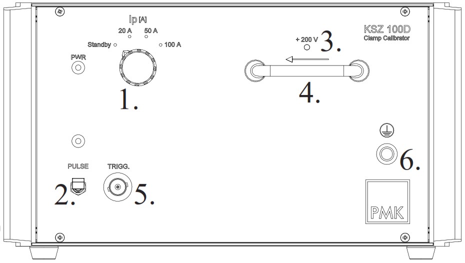
| 1. Rotary switch “Ip (A)” from 20 A up to 100 A 2. “PULSE” trigger switch and indicator LED 3. LED ,,200 V” |
4. Contact bar for current clamp or hall device 5. Trigger output 6. Earth ground |
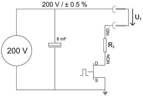
Functionality, Schematic
| Functionality: | Schematic KSZ 100D: |
| The functionality of the KSZ100 D results of the schematic. The pulse current is generated from a capacitor battery flowing through a precise non-inductive resistor R1 and a fast switching transistor. The value of the pulsed current is determined by the voltage U1 and the resistance R1. U1 is stabilized. At the contact bar a clamp device can be connected. Current transformers can be connected via power lead to the safety connectors. |
 |
User Instructions
![]() Do not switch output current while testing.
Do not switch output current while testing.
![]() Make sure the Calibrator is set to Standby or turned off while removing or exchanging the contact bar.
Make sure the Calibrator is set to Standby or turned off while removing or exchanging the contact bar.
Let the unit warm up by pulsing continuously for one minute prior to your tests. Follow the general instructions:
- Turn on KSZ 100 D by pressing the switch at the backplate. The LED “PWR” at the front of the calibrator is blinking. While the rotary switch “Ip (A)” is set to standby no power is present at the contact bar.
- Wait until the LED “200 V” is lit (approx. 30 seconds)
- Connect the clamp or hall device to the contact bar. In case of hall devices remove the bar by EN pulling it slowly out of its sockets.
- Connect trigger output to an oscilloscope if needed.
- Set desired value on rotary switch “Ip (A)” The LED “PWR” is lit.
- Activate switch “PULSE” to start the test. The red LED “PULSE” is blinking.
Scope of Delivery
| Items | Qty |
| Generator | 1 |
| Power cord | 1 |
| Instruction manual | 1 |
| Calibration certificate | 1 |
Option for KSZ 100D
| Options | Order No. |
| Interlock | INTERL-KSZ |
| Control cable (2 m) for connection to a closing contact (protective cover). Connection to the device via LEMO-Push-Pull connector on the back of the device. |
 |
Interface Description KSZ 100D
The remote control commands for transfer via USB or optional GPIB / IEEE are based on the RS232 interface.
Configuration of the RS-232 interface
| Baudrate: 19200 | Data bits: 8 | Parity: none | Stop bits: 1 |
Protocol
Communication takes place in a master-slave mode with KSZ 100 acting as slave. The KSZ 100 device responds to commands sent from outside. No communication takes place without such a command.
A binary protocol is used, where the length of each command is fixed. For each command there is a response with defined length. Since the number of bytes that must be transmitted for a specific command is defined, no control characters such as carriage return are needed to mark the end of a command.
The master must wait for the response after each command before the next command may be sent. The KSZ 100 device sends the response only when the command has been completely processed. The device is ready to receive a new command.
The following commands are defined:
| Write register | Command: ‘ R ‘ <nn><lo><hi><cs> Answer: <ans> nn: Register number (8-bit) lo, hi: Value (16 bit), low and high byte cs: 8 bit checksum ans: Answer code 6 = OK 7 = Error |
| Read register | Command: ‘ r ‘ <nn> Answer: <ans><lo><hi><cs> ans: Answer code 6 = OK 7 = Error nn: Register number (8-bit) lo, hi: Value (16 bit), low and high byte cs: 8 bit checksum |
| Device info | Command: ‘ I ‘ <nn> Answer: <ans><lo><hi><cs> ans: Answer code 6 = OK 7 = Error nn: Info type lo, hi: Value (16 bit), low and high byte cs: 8 bit checksum |
Timeout
A maximum timeout of 1 second is allowed between two consecutive bytes. If the pause is longer, the command is aborted with an error message. The device is ready to receive a new command.
Calculation of Checksum
To check whether a command was transmitted without errors, all transmitted bytes except the response code are added up as an 8 bit number in the receiver. An overflow is ignored. In case of error-free transmission, the sum is 0.
Examples
Write access to register 4, Value is 2000:
| Command: | ‘R’ (0x52) |
| nn | 0x04 |
| lo | 0xD0 |
| hi | 0x07 |
| cs | 0xD3 |
Read access to register 7, Value is 5000:
| Command: | ‘r’ (0x72) |
| nn | 0x07 |
| lo | 0x88 |
| hi | 0x13 |
| cs | 0xEC |
Register Numbers
| Reg. | Function | Unit /Scaling | Read /Write |
| 0 | Firmware version Bit 0..7: Subversion Bit 15..8: Main version |
read-only | |
| 1 | Status register Bit 0: High voltage on Bit 1: Ready to start testing Bit 2: Remote access active Bit 3: Pulse active (continous) Bit 4: Trigger Bit 5: Discharge relay active Bit 7: Protective cover open Bit 8: Pulse select 1 Bit 9: Pulse select 2 Bit 10: Pulse select 3 Bit 11: Pulse select 4 Bit 15: Error (must be acknowledged) |
read-only | |
| 2 | Control word Bit 0: Remote access on / off Bit 1: High voltage on / off Bit 2: Discharge relay on / off Bit 8-11: Pulse selection |
read /write | |
| 3 | Command register Bit 0: Pulse off Bit 1: Pulse on Bit 15: Reset error |
write only | |
| 4 | Pulse width Range 10 μs .. 2000 μs |
1 LSB = 1 μs | read /write |
| 5 | Pulse period Range 500 ms .. 5 s |
1 LSB = 1 ms | read /write |
| 6 | Current actual value | 1 LSB = 1/16 A | read-only |
| 7-19 | Register | ||
| 20 | GPIB adress (0 .. 15) | read-only |
Device Information
| InfoType | Function |
| 0 | Protocol version Bit 15..0 : version This document corresponds to protocol version 1 |
| 1 | Device type Bit 15..0 : Type The device type is the hardware version. KSZ 100D has the identifier 0x0200. For further extensions is range 0x0200 – 0x02FF reserved for KSZ 100D. |
| 2 | Parameter version Bit 0..7: Subversion Bit 15..8: Main version The parameter description in this document corresponds to version 1.0. This version identifier is managed separately for each device type. Different devices can use the same parameter version number, even if the parameters for these devices are different. |
| 3 | Mainboard version |
| 4 | Assembly variant |
| 5 | Serial number of main board, low word |
| 6 | Serial number of main board, high word |
| 7 | Serial number of device |
Notes
Copyright © 2021 PMK – All rights reserved.
Information in this publication supersedes that in all previously published material. Specifications are subject to change without notice.
M94-KSZ100D-000
Revision 09.2021
Documents / Resources
 |
PMK KSZ100 D Current Probes Calibration Generator [pdf] Instruction Manual KSZ100 D, Current Probes Calibration Generator, Calibration Generator, Current Probes Generator, Generator, KSZ100 D |


